Conceptual Design of a Thrust-Vectoring Tailcone for Underwater Robotics
by
Michael T. Nawrot
Submitted to the
Department of Mechanical Engineering
in Partial Fulfillment of the Requirements for the Degree of Bachelor of Science in Mechanical Engineering
at the
Massachusetts Institute of Technology June 2012
0 2012 Massachusetts Institute of Technology. All rights reserved.
ARCHIVES
MASSA INS E
OF TECHNOGY
JUN 2 8 2012
LIBRARIES
S ign ature o f A u th or... ... ... Department of Mechanical Engineering
June 1, 2012
C ertified b y ... . ... ... ... ... Amos G. Winter octoral Research Associate, MI TD ational Design Center
A ccepted by... . .
Samuel C. Colli fessor o echanical Engineering Undergraduate Officer
Conceptual Design of a Thrust-Vectoring Tailcone for Underwater Robotics
by
Michael T. Nawrot
Submitted to the Department of Mechanical Engineering on June 1, 2012 in Partial Fulfillment of the Requirements for the Degree of
Bachelor of Science in Mechanical Engineering
ABSTRACT
Thrust-vectoring on Autonomous Underwater Vehicles is an appealing directional-control solution because it improves turning radius capabilities. Unfortunately, thrust-vectoring requires the entire propulsion system be articulated in two degrees of freedom. Consequently, substantial internal volume must be utilized for this system, reducing payload and battery capacity. To combat this problem, an alternative thrust-vectoring system is desired for an existing vehicle. A number of alternative design strategies and concepts are explored herein. One design concept is then chosen and feasibility calculations are performed. Analysis of hydrodynamic loading, actuators, bearings, and structural components is conducted. The design is then reviewed and improvements are suggested.
Thesis Supervisor: Amos G. Winter
ACKNOWLEDGEMENTS
I would like to acknowledge several people who were indispensible to the completion of this project. First, I would like to thank my thesis supervisor, Amos Winter, who provided me with critical guidance and advice throughout the project. I would also like to thank Jakob Schmidt and the rest of the Bluefin Robotics Corporation for providing a challenging problem, help with brainstorming, and technical information. I also owe many thanks to Emily Tow for being a constant source of thesis-related information, Bayley Wang for his computing hardware, Duncan Townsend for his help with recovering my computer, Laura Royden for her moral support, and Rebecca Colby for ensuring that I continue to eat and sleep. Without the assistance of these people, this project would not have happened.
TABLE OF CONTENTS ACKNOWLEDGEMENTS 3 TABLE OF CONTENTS 4 LIST OF FIGURES 5 LIST OF TABLES 8 1. INTRODUCTION 9 2. DESIGN APPROACH 11 2.1. Design Specifications 11 2.2. Design Considerations 11 2.3. Design Strategy 16 3. DESIGN CONCEPTS 17
3.1. First-Order Duct Force Calculations 17
3.2. Proposed Design Concepts 20
3.2.1. Direct Pivot Design Concept 22
3.2.2. Pushrod Pivot Design Concept #1 25
3.2.3. Pushrod Pivot Design Concept #2 27
3.2.4. Floating Pivot Design Concept #1 28
3.2.5. Floating Pivot Design Concept #2 30
4. DESIGN ANALYSIS 35
4.1. Moment Estimation and Actuator Motor Selection 35
4.2. Additional Hydrodynamic Analysis 47
4.3. Load Analysis and Bearing Selection 51
5. DESIGN EVALUATION 62
5.1. Feasibility 62
5.2. Future Modeling Work 63
5.3. Recommended Design Alterations 64
6. CONCLUSION 65
LIST OF FIGURES
Figure 1.1: Thrust vectoring, applied here to a rocket, can be used on an AUV as an alternative to control
surfaces (1). 9
Figure 1.2: Bluefin-21 AUV. The approximate volume occupied by the current tailcone is shown (2). 10 Figure 2.2.1: A rendering of the current Bluefin-21 tailcone, with gearmotor, yaw and pitch pivot points,
yaw actuator, duct, and stator labeled. 12
Figure 2.2.2 a: Rzeppa-type (4) b: Tripod-type (5) c: Flexure-type (6) d: U-joint (7) 14 Figure 2.2.3: The Taylor Race Engineering aluminum tripod housing, measuring 84 mm in diameter, 30 mm in width, with a mass of 211 grams, is lightweight and reasonably compact. It is compatible with
off-the-shelf tripods, also available through Taylor Race Engineering (8) 15
Figure 3.1.1: Convention for lift, drag, and moment on a ring airfoil/duct. Chord is given by c, inner diameter is given by d, center of pressure distance from leading edge is xe, and angle of attack is given by a. Moments are taken around the quarter chord point. Lift is taken as normal to the flow, not the
duct. (9) 17
Figure 3.1.2: Non-dimensional center of pressure as a fraction of chord length versus angle of attack for
an annular Clark-Y airfoil of aspect ratio 3. (9) 18
Figure 3.1.3: The first-order estimated location for the center of pressure on the Bluefin-21 duct. 19 Figure 3.2.1: The direct pivot approach locates a traditional pin-type pivot at the center of pressure. The duct is fastened to the pin and torque is generated by either linear or rotary motors. This concept is similar to the existing system, but with the duct relocated relative to the pivot. 20
Figure 3.2.2: The pushrod style pivot uses opposing-motion pushrods, mounted external to the duct's pivot point, to create rotation about a point without hardware itself. The pushrods can be mounted
anywhere within the plane of the desired pivot. 21
Figure 3.2.3: The floating pivot concept constrains a piece of hardware, mounted external to the duct, to motion in an arc centered at the desired pivot point. The requisite hardware can be mounted anywhere in space, provided its arc of motion is located about the center of pressure. 21 Figure 3.2.1.1: A sample direct pivot gimbal design. The bearing for the flexible shaft joint mounts to the
yaw pivot, so as to rotate with the duct. 22
Figure 3.2.1.2: A sample actuation scheme for the direct pivot design, using linear actuators functioning
similarly to the current Bluefin-21 tailcone. 23
Figure 3.2.1.3: An overlay of the Taylor Race Engineering aluminum tripod housing on the Bluefin-21 duct. It is apparent that very little space is available for coincident pivot point hardware. 24 Figure 3.2.2.1: Pushrod concept #1 uses three independently controlled pushrods mounted to the exterior of the duct core. One end of each pushrod features a simple pivot, while the other end features
a ball-joint 25
Figure 3.2.3.1: A variation of the pushrod style design presented in Section 3.2.2. By coupling two
pushrods to one control arm, the axial degree of freedom is eliminated. 27 Figure 3.2.4.1: Asymmetric four-bar linkage that achieves virtual pivot point. The virtual pivot point
moves slightly axially and radially. 28
Figure 3.2.4.2: Possible implementation of asymmetric four bar floating pivot concept. Duct-side joints are two degree of freedom u-joints, AUV-side joints are three degree of freedom ball-joints. 29
Figure 3.2.5.1: A cross-sectional side view of the spherical floating pivot design. Note that the propulsion motor limits the minimum length of the assembly. A smaller diameter motor shortens the entire system. 30 Figure 3.2.5.2: Top view of the spherical floating pivot design. Note that the exterior ball transfers are located in an orthogonal plane to those inside of the spherical housing. This is done to properly
constrain the duct. 31
Figure 3.2.5.3: A view of the spherical floating pivot drive system. Note that there is adequate clearance between the yaw gear support bearings and the pitch gear, as well as the inner ball transfer and the pitch actuator. The pitch gear and propeller bearings, as well as the drive shaft and propulsion motor are
not shown here. 32
Figure 3.2.5.4: An exploded view of the primary support beam and floating yaw-gear assembly. 33
Figure 3.2.5.5: A detailed view of a support bearing in its trough. The radii of the surfaces can be
adjusted to minimize rubbing. 34
Figure 4.1.1: The Bluefin-21 duct, shown on the right, features a very different airfoil profile from that of the Clark-Y duct analyzed by Fletcher. Note the change in profile, as well as the angle of the chordline
relative to the duct axis 36
Figure 4.1.2: CFD versus experimental results for the Clark-Y duct. Agreement is poor due to coarse
mesh settings. 38
Figure 4.1.3: Lift and drag acting at the center of pressure, some distance / from the origin, generating a
pitching moment. Image modified from Fletcher (9) 39
Figure 4.1.4: Experimental Clark-Y duct center of pressure results versus CFD center of pressure results.
Error is given with respect to normalized center of pressure, not chord. 40
Figure 4.1.5: Center of pressure versus angle of attack for the Bluefin-21 duct. CFD results are presented, and then corrected to a maximum estimated value based on error calculations from the Clark-Y duct
results. 41
Figure 4.1.6: The horizontal lift components of the diagonal stator pairs cancel to give a purely vertical
lift force. 42
Figure 4.2.1: The center of pressure versus angle of attack for both Clark-Y and Bluefin Duct. The
agreement between the Clark-Y CFD and experimental is much improved. 48
Figure 4.2.2: Plots of lift, drag, and moment coefficients for both Clark-Y and Bluefin-21 ducts. The agreement between Clark-Y CFD results and Fletcher's experimental results is improved over those
presented in Section 4.1. 49
Figure 4.2.3: Propeller axial force as a function of vehicle speed. Note that the force is exactly quadratic
with vehicle speed. 50
Figure 4.3.1: An axial view of a tripod joint, illustrating single-point-of-contact torque generation: the worst-case radial loading possible for tripod bearings, propeller bearings, and propeller shaft bearings.
53
Figure 4.3.2: Coordinate system used for developing statics model. 54
Figure 4.3.3: Definition of effective angle of attack and lift angle, with respect to vehicle coordinate
system. 55
Figure 4.3.6: Hertzian contact normalized von Mises Stress versus normalize depth in the spherical
LIST OF TABLES
Table 2.1.1: Design requirements for Bluefin-21 Tailcone 11
Table 2.2.1: Sample propulsion motor specifications for Aerotech, Inc S Series Brushless, Frameless Torque Motor. It is evident from these specifications that a motor of these dimensions could provide the
requisite performance (3) 13
Table 2.2.2: Flexible shaft joint design comparison 14
Table 4.1.1: Flow settings used for each statorless duct 37
Table 4.1.2: Summary of torque estimates for maximum travel in one degree of freedom (yaw or pitch)
at full speed and full actuation rate. 44
Table 4.1.3: A sample actuator and gearbox selection process is shown. In this case, the housing-to-ambient thermal resistance must be 10% of nominal to avoid damaging the motor. It is important to
note that this is achievable, and that the torque estimates are incredibly conservative. 47
Table 4.2.1: Propeller angular velocity, torque, power, and axial force as a function of vehicle speed. 50 Table 4.3.1: Equivalent radial load factors for ball bearings, adapted from Shigley's Mechanical
Engineering Design (14) 52
Table 4.3.2: Basic specifications for a thin section Timken bearing for application as a propeller support
bearing (13) 53
Table 4.3.3: Basic specifications for a torque tube Timken bearing for application as a propeller shaft
bearing (13) 54
Table 4.3.4: Summary of the geometry used in solution of component forces. 59
Table 4.3.5: Summary of maximum forces experienced by various components over +/- ten degree travel
in pitch and yaw. 59
1. INTRODUCTION
This work exists primarily as a conceptual study for alternative designs to an existing thrust vectoring tailcone, currently in use on the Bluefin-21 Autonomous Underwater Vehicle (AUV), produced by Bluefin Robotics Corporation. Thrust vectoring redirects thrust for directional control of a vehicle, as opposed to using control surfaces to redirect the external flow. Figure 1.1 illustrates this principle.
Center Line I : Thrust Une
gimbal angle - a:--- a I
cente of torque cg torque cg
Thrust Thrust Thrust
gimbal angle 0||||||
Figure 1.1: Thrust vectoring, applied here to a rocket, can be used on an AUV as an alternative to control surfaces (1).
The Bluefin-21, shown in Figure 1.2, uses a ducted propeller on a two degree of freedom gimbal for propulsion and directional control (herein referred to as the tailcone). This configuration was chosen over a simpler control surface scheme due to the reduced turning radius made possible by thrust vectoring. Unfortunately, the current configuration occupies a
assembly is reduced, the vehicle can carry additional batteries or payload, improving overall mission capability.
Tailcone Assembly
Figure 1.2: Bluefin-21 AUV. The approximate volume occupied by the current tailcone is shown (2).
The goal of this design study was to explore alternative tailcone actuation schemes which could significantly reduce the volume occupied by the system. A number of concepts were proposed and qualitatively assessed. A single concept was then chosen and a first-order feasibility analysis was performed. The analysis included component packaging, actuator specification, bearing sizing, and stress analysis. A first-order hydrodynamic analysis was also conducted to estimate external loads on the system.
2. DESIGN APPROACH
2.1. Design Specifications
A set of Bluefin specified design requirements for the new 21" tailcone are listed in Table 2.1.1 below.
Table 2.1.1: Design requirements for Bluefin-21 Tailcone Design Requirement Specification
Size Shorter than 21"; smallest possible design preferred Propulsion power 1-2 kW
Noise Minimal
Actuation range +/- 150 pitch and yaw
Actuation speed 300/second Actuation frequency +/- 10 at 5 Hz
Vehicle speed 6 Knots Operating temperature -20 to 122 OF
Power Supply 60 V @ 40-50 A max.
Hydrodynamics Minimal modification to current configuration 2.2. Design Considerations
The primary requirements focused on in this design study were size, actuation characteristics, and hydrodynamic modification. Vehicle speed manifested itself in loading, and therefore component sizing; however, propulsion, power supply, operating temperature, and noise remained secondary in concept assessment. Electrical power supply requirements were taken as flexible, since voltage can easily be regulated; as such, voltages were largely ignored. Additionally, temperature restrictions were regarded as being a factor in detailed materials
choice and control electronics, and were also largely ignored.
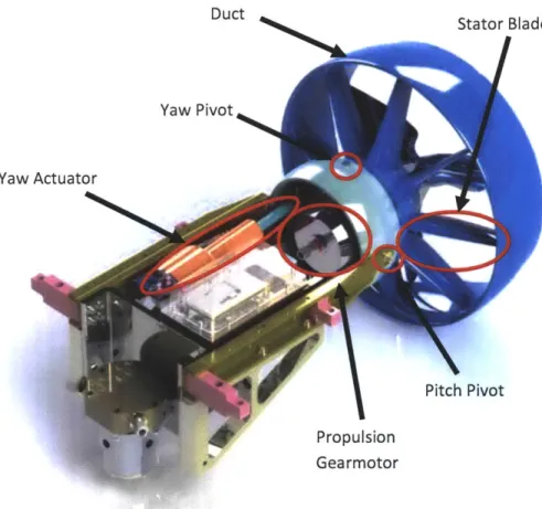
Noise and propulsion power were considered in more detail. In the current tailcone design, shown in Figure 2.2.1, the main source of noise is the propulsion gearmotor. Consequently, all proposed design concepts assumed a direct-drive motor for propulsion. Based on propeller performance, a motor capable of 24.5 N-m of torque at 600 rpm (1.5 kW) is required. Specifications for a possible propulsion motor are given in Table 2.2.1. Though the
sample motor figures are non-ideal for this application, they are simply used for reference: the ideal motor will have similar performance, and since electric motor performance is dictated by thermal and electrical geometry, similar size. The propulsion motor is therefore assumed to be of nine inch diameter and three inch length for all design concepts, based on the motor presented in Table 2.2.1. Detailed propulsion motor selection is deferred to future development efforts.
Duct
Stator Blade
/
Figure 2.2.1: A rendering of the current Bluefin-21 tailcone, with gearmotor, yaw and pitch pivot points, yaw actuator, duct, and stator labeled.
Table 2.2.1: Sample propulsion motor specifications for Aerotech, Inc S Series Brushless, Frameless
Torque Motor. It is evident from these specifications that a motor of these dimensions could provide the requisite performance (3)
Motor Model Unit
Winding Designation Performance Specifications
Stall Torque, Continuous N-m
Peak Torque N-m
Rated Speed rpm
Power Output, Continuous W
Length of Winding, Frameless Motor mm Outside Diameter, Frameless Motor mm.
Rotor Bore Diameter mm
s S-240-43 B 10.73 42.90 1200 1347.9 42.7 239.2 120.6
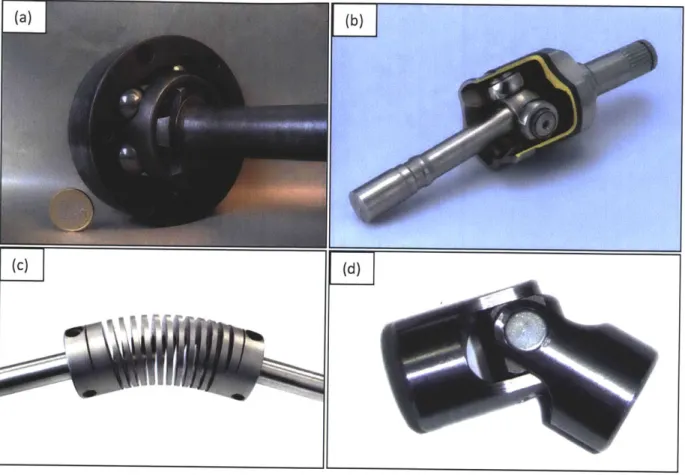
A direct-drive motor, while providing substantially reduced noise and part count, introduces a geometric constraint: in the existing Bluefin tailcone designs, the gearmotor is mounted on the gimbal and moves with the ducted propeller. This is not easily achievable in a direct-drive configuration, as the motor diameter is too large for reasonable motion to be achieved within the fairing enclosing the tailcone. As such, power must be transmitted from the propulsion motor to the propeller via a flexible shaft joint. Four possible shaft joint designs, shown in Figure 2.2.2a-d, are outlined in Table 2.2.2.
Figure 2.2.2 a: Rzeppa-type (4) b: Tripod-type (5) c: Flexure-type (6) d: U-joint (7)
Table 2.2.2: Flexible shaft joint design comparison
Joint Design Advantages Disadvantages
Rzeppa joint e Smooth power transmission e Large diameter
e Constant velocity * Heavy
* Loose parts generate noise
e Difficult to acquire
Tripod joint e Smooth power transmission e Large Diameter
* Constant velocity e Potential for noise
e Lightweight
Flexure e Smooth power transmission e Elasticity between shaft and
coupling e Constant Velocity propeller
* Lightweight e Potential shaft whip problem
0 Low noise e Torque required to bend
U-joint 0 Lightweight * Not constant velocity
* Easy to implement * Noise at large deflection
Rzeppa joints, most commonly used in automotive applications, were immediately eliminated. Commonly available Rzeppa joints are sized and built for power and high-torque applications, so off the shelf Rzeppa joints are exceedingly large and heavy. Additionally, the ball bearings used for motion coupling tend to generate excessive noise. U-joints were also quickly eliminated, as they are prone to excessive noise and vibration at large angles of deflection, due to their non-conjugate action. Of the remaining options, flexible couplings are perhaps the simplest solution; however, the couplings rely on deformation, so their behavior at large deflections may be unpredictable. This deformable nature could potentially lead to shaft-whip and fatigue problems. The deformation also creates an increasing force with increasing deflection, demanding additional work from the actuators. Regardless, the option is an entirely viable solution, and all designs presented herein could be adapted to work with said coupling.
Consequently, the tripod joint was selected for shaft power transmission. The behavior of the tripod joint is very predictable, and a reasonably lightweight and compact version is available through Taylor Race Engineering, as shown in Figure 2.2.3.
Figure 2.2.3: The Taylor Race Engineering aluminum tripod housing, measuring 84 mm in diameter, 30 mm in width, with a mass of 211 grams, is lightweight and reasonably compact. It is compatible with off-the-shelf tripods, also available through Taylor Race Engineering (8)
2.3. Design Strategy
Three design strategies were originally consider for reducing the size of the existing tailcone:
* Integrate actuation and propulsion into one motor " Move to an external actuation system
e Move the pivot point to center of pressure
The first strategy would involve the implementation of a spherical motor: a motor that can rotate continuously about its primary axis while being able to move the primary axis in two degrees of freedom. Such motors have been the subject of research for decades, but none are available commercially, and the idea was ruled out due to feasibility issues.
The second strategy involved externalizing the yaw and pitch actuators to increase available internal volume. However, the strategy was quickly eliminated, as it would interfere significantly with the hydrodynamics of the vehicle. Additionally, the actuators would be exposed to external impact, which would make the AUV very susceptible to damage.
The strategy of moving the pivot point to the center of pressure was thus adopted. Lift and drag on an object moving through a fluid are generated by pressure distributions over the objects surface. The integral of the pressure over the surface gives the resulting forces; those forces can be thought of as acting through a single point on the body. The point through which these forces act is called the center of pressure, and no moments are generated around that point. If a lifting body is held aft of the center of pressure, the body will pitch up; if the body is held fore of the center of pressure, it will pitch down. Therefore, placing the pivot point of the tailcone assembly at the center of pressure of the ducted propeller would generate no pitching moment, and the required actuators would become substantially smaller.
3. DESIGN CONCEPTS
3.1. First-Order Duct Force Calculations
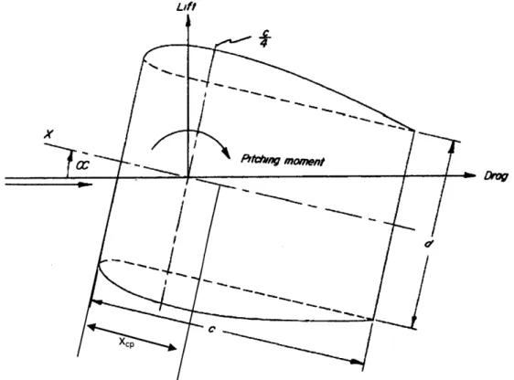
Before meaningful design concepts could be generated, the center of pressure of the ducted propeller assembly needed to be estimated. Fletcher presents experimental results for lift, drag, and pitching moment of five ring airfoils in non-axial flow in NACA Technical Note 4117 (9). The ducts were revolutions of the Clark-Y airfoil profile with chordline at zero angle of attack. The results are presented based on the conventions shown in Figure 3.1.1.
Lift
Figure 3.1.1: Convention for lift, drag, and moment on a ring airfoil/duct. Chord is given by c, inner diameter is given by d, center of pressure distance from leading edge is xe, and angle of attack is given by a. Moments are taken around the quarter chord point. Lift is taken as normal to the flow, not the duct. (9)
Fletcher gives the non-dimensional center of pressure as a fraction of the chord length, and presents the results for five different aspect ratios, defined by Equation 1, where aspect ratio is A, chord is c, and duct diameter is d.
d
A = -C (1)
For the Bluefin-21 duct, the chord is 0.1239 meters and the diameter is 0.3860 meters, giving an aspect ratio of 3.12. Fletcher's center of pressure results for a duct of aspect ratio equal to 3 are shown in Figure 3.1.2.
0.6 0.5 0.4 -x,,/c 0.3 0.2 0.1
0
- I 0 5 10 15 20 25 30 35Angle of Attack (degrees)
Figure 3.1.2: Non-dimensional center of pressure as a fraction of chord length versus angle of attack for an annular Clark-Y airfoil of aspect ratio 3. (9)
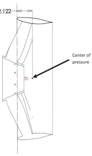
Ideally, the pivot point could remain at the center of pressure under all conditions. Unfortunately, as visible in Figure 3.1.2, the center of pressure shifts with change in angle of attack. The hydrodynamic forces also increase with angle of attack, so the pivot location that most easily minimizes forces is at the center of pressure for the worst-case loading: i.e. highest angle of attack seen. In this case, the maximum angle of attack can be taken as fifteen degrees: full actuation in one degree of freedom. At this angle of attack, the center of pressure is at 43.5% of the chord from the leading edge. To first-order, ignoring effects of airfoil profile, airfoil angle
of attack, and the duct stator, the center of pressure on the Bluefin-21 duct is approximated as shown in Figure 3.1.3.
2.122
Center of pressure
Figure 3.1.3: The first-order estimated location for the center of pressure on the Bluefin-21 duct.
As made apparent from this estimate, the center of pressure is likely to be aft of the duct mounting point and contained within the propeller. As such, creating a pivot point at the center of pressure proves to be challenging: space is limited, and the pivot may have to be enclosed in the rotating housing of the propeller. Moving the pivot point as close to the center of pressure as possible, however, still promotes significant downsizing of actuators. In the current configuration, the pivot point is 6.6 inches from the estimated center of pressure. By moving the pivot to the aft edge of the duct mounting, the pivot-to-center-of-pressure distance would be reduced by 80%, resulting in an 80% reduction in required torque, and thus a significant reduction in tailcone volume. However, placing a pivot point inside the duct is still challenging, for space is very limited.
3.2. Proposed Design Concepts
Three design approaches, outlined in Figure 3.2.1, Figure 3.2.2, and Figure 3.2.3, were considered for moving the pivot point rearward. The first approach simply integrates traditional pivot points into the duct mounting. Another approach utilizes pushrod style controls to allow for parallel, rather than series actuation, and more flexibility in hardware placement. The final approach rotates the duct around a virtual pivot, allowing more ideal pivot placement at the expense of geometric complexity. All three approaches require the propeller shaft's flexible joint be coincident with the pivot point, introducing an additional constraint. Variants of each concept
are discussed in Section 3.2.1 through Section 3.2.5.
Figure 3.2.1: The direct pivot approach locates a traditional pin-type pivot at the center of pressure. The duct is fastened to the pin and torque is generated by either linear or rotary motors. This concept is similar to the existing system, but with the duct relocated relative to the pivot.
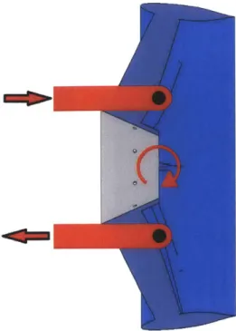
Figure 3.2.2: The pushrod style pivot uses opposing-motion pushrods, mounted external
to the duct's pivot point, to create rotation about a point without hardware itself. The pushrods can be mounted anywhere within the plane of the desired pivot.
Figure 3.2.3: The floating pivot concept constrains a piece of hardware, mounted external to the duct, to motion in an arc centered at the desired pivot point. The requisite hardware can be mounted anywhere in space, provided its arc of motion is located about the center of pressure.
Direct Pivot Design Concept
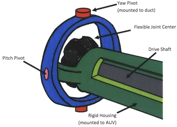
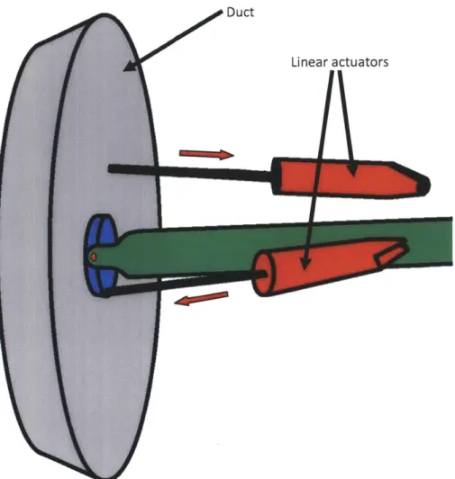
The direct pivot design requires two pin-type pivot points be collocated at the center of pressure. A simple gimbal-like design can be used for this, with the propeller-side flexible joint bearing mounted to the outermost gimbal assembly. An illustration of this concept is shown in Figure 3.2.1.1. A direct pivot design can be actuated using linear actuators, similarly to the existing Bluefin-21 tailcone, as shown in Figure 3.2.1.2.
Yaw Pivot
* U000(mounted to duct)
Flexible Joint Center
Drive Shaft Pitch Pivot
Rigid Housing (mounted to AUV)
Figure 3.2.1.1: A sample direct pivot gimbal design. The bearing for the flexible shaft joint mounts to the yaw pivot, so as to rotate with the duct.
Duct
Linear actuators
E
Figure 3.2.1.2: A sample actuation scheme for the direct pivot design, using linear actuators functioning similarly to the current Bluefm-21 tailcone.
The direct pivot design is appealing for its inherent simplicity. The design represents a significant improvement over the existing design; it reduces the required actuator output and shifts the entire assembly approximately six inches aft. A design using rotary actuators could further compact the mechanism, since linear actuators tend to be less space efficient. Unfortunately, this design is not feasible with the current duct and tripod joint, due to limited space within the duct. Figure 3.2.1.3 shows that the suggested tripod joint housing is too large for pivot hardware to be mounted radially to it.
To-scale tripod joint
Figure 3.2.1.3: An overlay of the Taylor Race Engineering aluminum tripod housing on
the Bluefin-21 duct. It is apparent that very little space is available for coincident pivot point hardware.
While this design can be modified for use with a flexure coupling (thus reducing the required diameter of the gimbal assembly), the additional length and potential shaft whip of such a joint discourage further exploration in this study. This concept is discarded in favor of a more compact design presented in Section 3.2.5.
Pushrod Pivot Design Concept #1
A pushrod style design allows placement of mounting hardware outside the duct, avoiding the limited-internal-volume problem presented in Section 3.2.1. The pushrod design also creates two degrees of freedom through parallel hardware, rather than series hardware (i.e. the yaw pivot does not mount on the pitch pivot, as is done in Figure 3.2.1.1). One pushrod
implementation is shown in Figure 3.2.2.1.
Figure 3.2.2.1: Pushrod concept #1 uses three independently controlled pushrods mounted to the exterior of the duct core. One end of each pushrod features a simple pivot, while the other end features a ball-joint
This implementation uses three independent pushrods, each controlled by a rotary actuator at the base of their control arm. The control arm is affixed to the vehicle by a single degree of freedom pivot, and the pushrod is connected to the other end of the control arm in a similar manner. The pushrods are then connected to the duct via three degree of freedom ball-joints. Accounting for rigid bodies and constraints yields Equation 2.
7 bodies * 6 DoF - 3 ball
joints
* 3 DoF - 6 pivots * 5 DoF = 3 DoF (2)As made apparent in Equation 2, the system is under-constrained. By observation, there are two rotational and one translation degree of freedom. The translational degree of freedom is along the axis of the vehicle, and pure translational motion is achieved when all three pushrods move equally in one direction. As such, the duct needs an axial constraint, or the pushrod actuators need constant power for position-holding during straight-line cruise. Both options are feasible; however, the axial duct constraint adds mechanical complexity, while stalling the actuators requires improved thermal management to avoid runaway heating in the motor windings and eventual failure. As such, and alternative pushrod style design is proposed in Section 3.2.3.
Pushrod Pivot Design Concept #2
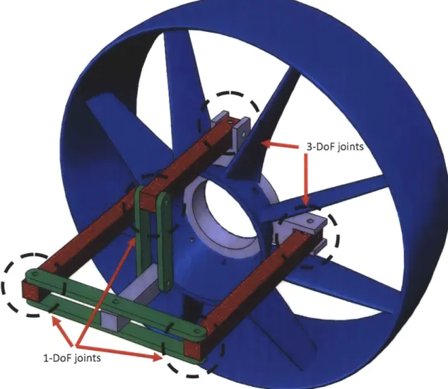
A modified version of the pushrod concept presented in Section 3.2.2 is shown in Figure 3.2.3.1. By linking two of the pushrods to the same control arm, one rigid body (six degrees of freedom) and one pivot constraint (five constraints) are eliminated, yielding one less degree of freedom. Consequently, the axial motion of the duct is eliminated, removing the additional mechanical complexity of an axial duct constraint. This design also eliminates the need for actuators to be under constant power, easing thermal design. However, for the pushrod ball-joints to be mounted in-plane with the desired pivot point, they must severely interfere with the hydrodynamics of the duct. The pushrod style design is therefore discarded in this study.
3-Do F joints
1-DoF joints
Figure 3.2.3.1: A variation of the pushrod style design presented in Section 3.2.2. By
coupling two pushrods to one control arm, the axial degree of freedom is eliminated.
Floating Pivot Design Concept #1
A floating pivot design benefits from remote mounting of hardware: possibly eliminating hydrodynamic interference, avoiding volume limitations within the duct, and enabling placement of the pivot closer to the center of pressure. One method for achieving a floating pivot is by use of an asymmetric four-bar linkage, as illustrated in Figure 3.2.4.1. While the portion of the linkage connected to the duct does not move along an exact arc, the spatial deviation of the "pivot point" is small enough to be accommodated by the flexure coupling or tripod joint.
Fixed to AUV
Virtual Pivot Point Fixed to duct
Figure 3.2.4.1: Asymmetric four-bar linkage that achieves virtual pivot point. The virtual pivot point moves slightly axially and radially.
This two dimensional concept is adapted into a three dimensional concept illustrated in Figure 3.2.4.2. In this concept, four connecting rods are affixed to the AUV by ball-joints with three rotational degrees of freedom. The duct is mounted to the opposite end of the connecting rods using joints with two rotational degrees of freedom, similar to a u-joint. Accounting for rigid bodies and constraints yields Equation 3.
5 bodies * 6 DoF - 4 ball joints * 3 DoF - 4 u joints * 4 DoF = 2 DoF (3)
This suggests that the linkage will create the necessary degrees of freedom, assuming no redundant constraints are present. Linear actuators could likely be implemented in the manner shown, with a ball-joint on one end, and a u-joint on the other end. Two actuators would introduce twelve degrees of freedom and fourteen constraints, resulting in a perfectly constrained system for a given actuator position. This design benefits from remote placement of mounting hardware (i.e. the location of the pivot point does not dictate the location of the linkage joints). However, the design requires a reasonable volume forward of the duct for actuation, and linear servo actuators are generally less space efficient than an equivalent rotary motor. Additionally, the axial and radial motion of the virtual pivot point is less than ideal. For these reasons, the design presented in Section 3.2.5 is pursued instead.
U-Joint Duct
Linear Actuator
Ball- joint
Figure 3.2.4.2: Possible implementation of asymmetric four bar floating pivot concept.
Duct-side joints are two degree of freedom u-joints, AUV-side joints are three degree of freedom ball-joints.
Floating Pivot Design Concept #2
To achieve ideal pivot placement and minimum volume, the design illustrated in Figure
3.2.5.1 through Figure 3.2.5.3 was chosen. The design utilizes four ball transfers (load bearing
balls that can rotate in two directions) on a spherical surface to constrain the duct to motion around the center of the sphere. Each ball transfer can only exert a radial force, because two spheres theoretically only contact at a single point. As such, each ball transfer acts as a single translational constraint. However, the ball transfers can only generate a positive force; otherwise separation of the surfaces will occur. For this reason, an extra ball transfer is needed to generate three translational constraints. This leaves the duct with three rotational degrees of freedom about the center of the sphere. The remaining rotational degree of freedom is dealt with through the gear train, discussed later.
Propulsion motor
Spherical Ball Transfer hou Ing
Tripod joint
Fairing
Figure 3.2.5.1: A cross-sectional side view of the spherical floating pivot design. Note that the propulsion motor limits the minimum length of the assembly. A smaller diameter
Figure 3.2.5.2: Top view of the spherical floating pivot design. Note that the exterior ball
transfers are located in an orthogonal plane to those inside of the spherical housing. This is done to properly constrain the duct.
The spherical shell utilizes very little space, allowing the actuation system to be placed within duct. Thus, the drive motor is the limiting factor in total system volume, as it needs to be enclosed within the vehicle fairing (as seen in Figure 3.2.5.1). Consequently, this design is appealing when maximizing vehicle payload.
The drive system, shown in Figure 3.2.5.3, utilizes two gear stages in series. The actuator controlling yaw is mounted to the primary support beam and drives a floating gear assembly. The pitch actuator is mounted to the floating yaw-gear assembly. This actuator drives the pitch-gear assembly, mounted rigidly to the duct. The pitch-gear assembly floats on the yaw-gear assembly using a similar mechanism as the yaw-gear assembly on the primary support beam.
Figure 3.2.5.3: A view of the spherical floating pivot drive system. Note that there is
adequate clearance between the yaw gear support bearings and the pitch gear, as well as the inner ball transfer and the pitch actuator. The pitch gear and propeller bearings, as well as the drive shaft and propulsion motor are not shown here.
A more detailed view of the floating yaw gear assembly is presented in Figure 3.2.5.4 and Figure 3.2.5.5. The two gears of the assembly sandwich a set of four bearings, which sit in concave troughs that form an arc centered at the pivot. The surface of the bearings is spherical, creating point-contacts that allow the cylindrical bearings to sit in the trough without jamming. The axes of the bearings are aligned radially to the axis of the floating gear assembly to permit arc-like motion. If the gear assembly attempts to move in any direction other than the prescribed
arc, the bearings attempt to lift out of the trough, forcing the separation of the gear assembly; however, this is not possible.
Each bearing provides two constraints: a normal force (radial to the bearing) and a retaining force keeping the bearing from moving in the trough (axial to the bearing). Since the bearings can only provide a positive normal force (else the surfaces would separate), a complementary bearing is required. It can thus be seen that three bearings (two along the upper trough, one along the bottom trough) would constrain the assembly to one degree of freedom. However, four bearings are used instead to reduce the radial load seen by an individual bearing when a torque is applied about the axis of the propulsion motor (described in Section 4.3). The floating yaw-gear is also coupled to the adequately constrained duct. While the yaw and pitch-gear assemblies prevent rotation about the axis of the duct, they introduce redundant constraints. To prevent over-constraining the system, loose tolerances should be held on the floating gear assemblies. The support bearings should only see loads from moments around the axis of the duct, and forces transmitted through the actuators. As will be shown in Section 4.3, these forces prove to be substantially lower than those seen by the ball transfers.
Figure 3.2.5.4: An exploded view of the primary support beam and floating yaw-gear assembly.
Figure 3.2.5.5: A detailed view of a support bearing in its trough. The radii of the
surfaces can be adjusted to minimize rubbing.
This design is analyzed in Section 4 and evaluated in Section 5. However, it is worth noting now that the maximum travel of the duct was reduced from +/- 15 degrees to +/- 10 degrees in the designs presented. This was done to avoid modification to the duct, given the center of pressure found by the procedure outlined in Section 4.1. An error in this procedure suggested the center of pressure to be further aft, and the spherical floating pivot design geometry was based on this assumption. The calculations were corrected, but due to time constraints, the geometry of the design could not be changed. Since the center of pressure was found to be further forward, this design can be modified to give the requisite travel, or an alternative design could be pursued (e.g. direct pivot).
4. DESIGN ANALYSIS
To assess the feasibility of the spherical floating pivot design, a general analysis of all critical components was done. Actuator options were investigated to assess the possibility for packaging actuation within the duct. A more refined hydrodynamic assessment was then conducted to better analyze the loading on actuators, bearings, and other components. The loading of components under static conditions was then calculated, and lifetime estimates were made where possible.
4.1. Moment Estimation and Actuator Motor Selection
For first-order approximation of the required actuator size, a basic model is needed for moments about the chosen pivot. The four primary causes of moments about the pivot are:
e Lift and drag from the duct at a given angle of attack e Lift and drag from the duct stator at a given angle of attack e Drag created by sweeping the duct radially through the water
" Gyroscopic forces from the propellers
e External impact
These contributions (excluding impact) are analyzed at full travel in one dimension (e.g. 15 degrees yaw) at full speed (3 m/s) at full actuation rate (30 degrees/sec).
For a sufficient estimate of duct forces to be made, a more accurate prediction of the center of pressure must be made. The center of pressure of an aerodynamic body is heavily influenced by its shape, as the pressure distribution over the surface determines its location. The total momentum change of the incoming flow determines lift and drag forces, which may be identical between ducts of similar dimensions and aspect ratios: however, the manner in which the flow is turned, and thus the location where the forces can be said to act (i.e. center of pressure) varies largely based on airfoil profile and airfoil angle of attack relative to the duct's
axis. Figure 4.1.1 shows the profile variation between the Bluefin-21 duct and the Clark-Y duct Fletcher uses in his characterization of ducts.
Figure 4.1.1: The Bluefin-21 duct, shown on the right, features a very different airfoil
profile from that of the Clark-Y duct analyzed by Fletcher. Note the change in profile, as well as the angle of the chordline relative to the duct axis
To adequately predict the center of pressure, an angle of attack sweep from zero to thirty degrees was conducted in the SolidWorks Flow Simulation 2011 computational fluid dynamics (CFD) package. The sweep was first run for a model of a Clark-Y duct with an aspect ratio of three, with conditions matching those presented by Fletcher. These results were then compared to the experimental results presented by Fletcher to ensure the simulations provided reasonable estimates. Finally, the simulations were run for the Bluefin-21 duct (without stator) for conditions approximating those seen in the field, and error margins derived from the Clark-Y
simulations were applied. For first order actuator calculations, mesh settings were kept coarse.
Table 4.1.1: Flow settings used for each statorless duct
Fletcher Clark-Y CFD Clark-Y CFD Bluefin-21
Fluid Air Air Water
Mach Number/Velocity .13 .13 3 m/s Static Pressure -- 101325 Pa 101325 Pa Static Temperature -- 293.2 K 293.2 K Dynamic Pressure 1190 Pa 1190 ± 5 Pa 4446 ± 10 Pa Wall Roughness -- 50 pm 10 4m Turbulence Intensity -- 10% 2 % Turbulence Length -- .542 mm .542 mm
Origin (as % of chord) 25% 25% 18.9%
The results for the CFD Clark-Y duct are plotted against the results presented by Fletcher in Figure 4.1.2. The results are normalized according to Equations 4-6, where d is duct inner diameter, c is duct chord, q is dynamic pressure, L is the lifting force, D is the drag force, M is the moment about the origin, Cd is coefficient of drag, C, is coefficient of lift, and Cm is moment coefficient. Note that the conventions are those defined in Figure 3.1.1, except moment is given the opposite sign for consistency with conventions used in the CFD results.
L I-qdc D qdc (4) (5) Cm = M (6) qdc2
Results for lift, drag, and moment coefficients are in poor agreement with those presented by Fletcher: however, this is purely a function of mesh settings, and improved results are
1.6 1.4 1.2 1.0 C1 0.8 0.6 0.4 0.2 0.0 0.9 0.8 0.7 0.6 0.5 C dd 0.4 0.3 0.2 0 . 0.0 0.40 0.35 0.30 0.25 0.15 0.10 0.05 0.00 5 0 5 10 15 20 25 30 3 - -dIEs -- *-- CFD -0- NACA TN 4117 0 5 10 15 20 25 30 3
Angle of Attack (deg)
Figure 4.1.2: CFD versus experimental results for the Clark-Y duct. Agreement is poor due to coarse mesh settings.
5
7IA
/ 4100 ,Onooe
0 5 10 15 20 25 30 35 -- 4-CFD -E- NACA TN 4117The center of pressure for a given angle of attack is derived from lift, drag, and moment. If lift and drag are taken to act through a point along the axis of the duct, as shown in Figure 4.1.3, then their location is the point which generates the correct moment about the origin. Trigonometry and moment balance lead to Equation 7a and Equation 7b for the center of pressure as a fraction of chord length.
Figure 4.1.3: Lift and drag acting at the center of pressure, some distance / from the
origin, generating a pitching moment. Image modified from Fletcher (9)
(7a) M = D -1 -sin(a) + L I -cos(a) C, =(Cd -sin(a) + C, cos(a))-C xc =-+'n c Cd -sin(a) + C, -cos(a) (7b)
The center of pressure for the Clark-Y CFD results is plotted against those presented by Fletcher in Figure 4.1.4, along with the error between the two. The error in center of pressure is given by Equation 8. It is worth noting that the 22% error in center of pressure at fifteen degrees corresponds to 9.5% of chord, which is more acceptable for a first order calculation than a 22% error may be perceived.
-+CFD -W- NACA TN 4117 ---A-- Xcp Error
Xcp 0.6 0.5 0.4 0.3 0.2 0.1 0 0n -35% -30% -25% -20% -15% -10% -5% % Error n0%-0 5 10 15 20 25 30
Angle of Attack (deg)
Figure 4.1.4: Experimental Clark-Y duct center of pressure results versus CFD center of pressure results. Error is given with respect to normalized center of pressure, not chord.
Using the results from CFD analysis of the Clark-Y duct, a reasonable adjustment to the CFD results for the Bluefin-21 duct can be made. The CFD results for the Bluefin-21 duct, as well as maximum estimated values computed to yield the same errors seen on the Clark-Y are shown in Figure 4.1.5. -4 - -. in
up-- A
0.051
L
' ""^ " '''-"'1-35%
0.00 .- 30% -0.05 -0.10 --0.15 - -- 20% XC -0.20 - A .. -' *.. -15% %Ero -0.25 -' -10% -0.30 --0.35 -5%Angle of Attack (deg)
Figure 4.1.5: Center of pressure versus angle of attack for the Bluefin-21 duct. CFD results are presented, and then corrected to a maximum estimated value based on error calculations from the Clark-Y duct results.
Based on these results, the location of the center of pressure appears to in front of the leading edge of the Bluefin-21 duct. While this is beneficial in the simplification of the design (i.e. moving to a direct pivot design), a calculation error prevented this from being apparent. The moment coefficient (used in Equation 7b to find the center of pressure) was improperly calculated when the chord length c was not squared in Equation 6. This resulted in a center of pressure similar in behavior to that shown in Fletcher, so the mistake was not immediately noticed. As such, the spherical floating pivot concept was designed for less favorably placed center of pressure. As such, all remaining calculations are done with the corrected center of pressure values, but with the "incorrect" design.
In the current configuration, the pivot point and the center of pressure in the corrected (i.e. "max") fifteen degree case are 33.6 mm apart. For estimation purposes, the lift and drag properties from Fletcher are used along with a dynamic pressure of 4446 Pascals. From Equations 4, 5, and 7a, the torque about the pivot is found to be 9.9 N-m.
To account for the stator segments, it is assumed each pair acts as an elliptic wing. It can be shown that an elliptic flat plate is characterized by Equations 8-10, where A is the wing aspect ratio, D is the span, S is the planform area, and a is the angle of attack in radians. (9) (10).
A = (8)
27r1 -a A+2 C2 Cdinduced -7RA (9) (10) The planform area for a pair of stator segments (herein referred to as S) is .01548 m2 and the span is taken to be the diameter of the duct, resulting in an aspect ratio of 9.6. For pure yaw or pure pitch of the tailcone assembly, one stator pair is at zero angle of attack, while another pair is at the yaw/pitch angle. The two remaining pairs each see a reduced angle of attack and mutually cancel portions of their lift contributions. A geometric argument for lift cancellation is given in Figure 4.1.6.
Figure 4.1.6: The horizontal lift components of the diagonal stator pairs cancel to give a purely vertical lift force.
By geometry, the angle of attack on the diagonal stator segments, aeff, is given by Equation 11. Ignoring effects created by the close proximity of the segments (i.e. downwash) skin friction, walls, sweep, and details of the stator airfoil profile, the total lift and drag generated is given by Equations 12 and 13.
aeff= tan(
L = a + tan -qS (12)
D )2 a2 +2-tan- '(a7 -2j.jqS (13)
For the area and span stated above, and using the same dynamic pressure as before, Equations 12 and 13 give the stator lift and induced drag to be 188.5 N and 8.54 N, respectively. If these forces act at same center of pressure as the duct, the torque generated by the stator segments equals 6.1 N-m. As the majority of the stator lies aft of the duct center of pressure, this is likely an overestimate. While the center of pressure of the stator segments cannot be determined accurately without some analysis of the specific geometry, it is reasonable to assume that it lies aft of the stator leading edge. Thus the stator segments may move the overall center of pressure closer to the pivot point. However, it will be assumed that they act through the same center of pressure to remain conservative in analyzing the spherical floating pivot design.
In addition to hydrodynamic loading from axial flow, some torque is required for sweeping the duct through the water, even while the vehicle is stationary. To estimate this torque, the duct is said to be moving through the water radially (i.e. angle of attack of ninety degrees). Fletcher gives the lift and drag coefficients to be 0.05 and 0.75, respectively. As such, the contribution from lift will be ignored. The density of seawater is taken to be 1025 kg/m3. The radial velocity of the duct is estimated as the product of the distance from pivot to duct center of pressure (shown to be similar at small and large angles of attack by Fletcher) and the maximum angular velocity of the duct in radians per second. Taking distance to be 33.6 mm and angular velocity to be 0.52 rad/s (as per Table 2.1.1), the radial velocity is approximately 17.6 mm/s. This velocity is two orders of magnitude smaller than the axial flow, meaning the dynamic pressure and drag will be four orders of magnitude smaller. Consequently, the torque from turning the duct in the fluid is ignored.
Finally, the gyroscopic effects of turning a spinning propeller are estimated. The propeller's moment of inertia about the shaft, as calculated in SolidWorks, is 2.4 x 10⁻³ kg-m2. Angular momentum, the product of inertia and angular velocity, is 0.151 kg-m2-s-1 at the
maximum propeller speed of 62.8 rad/s (3 m/s vehicle speed). Torque, the time-derivative of angular momentum, is the product of the propeller's angular momentum and the angular velocity about the pivot (0.52 rad/s from before). This results in a torque of 0.078 N-m, which is insubstantial when compared to hydrodynamic loading.
The results of the above estimates are summarized in Table 4.1.2.
Table 4.1.2: Summary of torque estimates for maximum travel in one degree of freedom (yaw or pitch) at full speed and full actuation rate.
Duct at 15 deg. 9.9 Nm
Stator at 15 deg. 6.1 Nm
Duct sweeping torque at 30 deg/s 5.7 mNm Propeller gyroscopic torque at 30 deg/s 78 mNm
Total 16.1 Nm
Based on these estimates, it is possible to specify the actuators required for the spherical floating pivot design. Given the tight space constraints, it is critical that the actuator be both sufficiently powerful and compact. Since an infinitesimally small electric motor could provide infinite power were it not thermally limited, the guiding design criterion will be winding temperature. The motors considered were Faulhaber brushless DC-servomotors coupled to Faulhaber precision planetary gearheads. These were the only options considered, due to their wide selection, thorough technical data, high torque capability, and proven success in other Bluefin tailcones.
Due to the arrangement of the yaw and pitch-gear assemblies in the proposed design, the yaw actuator is used as the limiting case: the yaw gear has a smaller radius than the pitch gear, thus the highest possible reduction is smaller and the radial and tangential forces on the motor shaft are higher. Since motor torque is proportional to current, and heat generation quadratic with current, it is favorable to minimize motor torque. This can be achieved by using a large reduction ratio; however, this increases the size of the system and reduces efficiency. As such, it is favorable to maximize the reduction in the final stage (i.e. planetary gearhead to yaw-gear reduction). To begin, a yaw-gear pitch of thirty-two teeth/inch of diameter was chosen. A coarse pitch is desired for increased tooth strength while a fine pitch is desired for maximizing the final reduction. A pinion with nine teeth (the smallest number commonly available) with a pitch of thirty-two is just large enough to fit on the 2-4 mm shafts available on the smaller Faulhaber
planetary gearheads. Thus, this is taken as the limiting case, and (based on the internal dimensions of the duct) a final reduction of 20:1 is the maximum achievable. The selection of the motor is then done by the process given below.
1. Select final reduction, gearbox, and motor. Motor shaft speed (omotor) is given by Equation 14, where Nfinal is the final reduction ratio, Ngearbox is the gearbox reduction, and
co is the required angular velocity at the duct pivot, in RPM.
Comotor = N 0l * Ngearbox - (14)
2. Using the motor shaft speed, find the frictional motor torque based on frictional coefficients given in the motor spec-sheet. The frictional motor torque xrf is given by Equation 15, where CO is the static friction torque and C, is the dynamic friction torque.
f = Co + C, -comotr (15)
3. The total torque demanded of the motor (Tmotor) should be calculated. This can be found by Equation 16, where igearbox is the efficiency of the planetary gearhead, r/final is the efficiency of the final reduction, and rcpivo is the torque about the duct pivot.
Tmotor f pivot (16)
fina- N ,gearbox- 7 -final gearbox
4. The power dissipated by the windings (Pw) is then found by Equation 17, in which R is the winding resistance and Km is the torque constant of the motor.
2
P,= T'"'' R (17)
5. Based on this power dissipation, the maximum allowable housing-to-ambient thermal
resistance (Rth,2) can be found by Equation 18. Tmax is the maximum allowable winding temperature, Ta is the ambient temperature, and Rth,1 is the thermal resistance between the windings and the housing.
Rth,2 Tnmax T RthI (18)
P,
6. The maximum allowable housing-to-ambient thermal resistance should be compared to the nominal value provided by Faulhaber. Reductions in thermal resistance are achievable
through heat-sinking and other thermal management techniques, but large reductions in thermal resistance are difficult to achieve.
7. Voltages, speeds, and loads should be checked using basic motor constitutive relationships to ensure operation is within reasonable limits. Repeat the process until a suitable actuator/gearbox combination is selected.
Table 4.1.3 presents a sample actuator selection. The actuator selected here is the six volt Faulhaber 1226-006-B brushless DC-servomotor coupled to the Faulhaber 256:1 12/4K planetary gearhead, whose spec-sheets are given in references (11) and (12). This motor and gearbox combination is used in the solid models presented in Figures 3.2.5.1 through 3.2.5.5. It will continue to be the actuator selection for the remainder of the design study.
Table 4.1.3: A sample actuator and gearbox selection process is shown. In this case, the
housing-to-ambient thermal resistance must be 10% of nominal to avoid damaging the motor. It is important to note that this is achievable, and that the torque estimates are incredibly conservative.
Motor Gearhead
Final Drive Ratio Gearhead Ratio Gearhead Efficiency Max RPM
@
PivotMax Torque
@
Pivot(Nm) Max Torque@
Gearhead (Nm) Torque@
Motor (Nm) Motor RPM Dynamic+Static Friction (Nm) Speed Constant Torque Constant Resistance Back EMF Current Voltage Drop Coulomb LossMax Operating Temp Ambient
Coil-Housing Resistance Housing Air Resistance (nom) Max act. Housing-Air Resist. Percent Reduction Faulhaber 1226 6 V windings Faulhaber 12/4 20.000 256 60% 5 16.1 0.847 0.0052 25600 0.00028892 3447 2.77 2.3 7.426747897 2.096 4.82 10.1 125 22 7 38 3.195 92% Rated Stall Max Cont. 0.3 7.19 60000 Int. 0.45 mNm rpm/V mNm/A Q V A V W C C K/W K/W K/W
4.2. Additional Hydrodynamic Analysis
While the models presented in Section 4.1 are adequate for initial feasibility assessment, more accurate models are desirable when pursuing a detailed design analysis, as is done in Sections 4.3 and 4.4. To improve the accuracy of load-related estimates, these three additions were made:
" Improved characterization of duct hydrodynamics
e Modeling of propeller thrust
" Torque about duct axis
To improve hydrodynamics characterization, the mesh and convergence settings in SolidWorks Flow Simulation 2011 were adjusted. To verify that the new settings gave more realistic results, they were first tested on the Clark-Y duct used in Fletcher's experiments and compared with his results. The same settings were then applied to the Bluefin-21 duct. The resulting center of pressure is presented in Figure 4.2.1. All sets of lift, drag, and moment data are plotted in Figure 4.2.2 (based on the conventions and general settings used in Section 4.1). The agreement between experimental and CFD results is much improved, and it is now reasonable to use the corrected Bluefin-21 CFD results for calculation of duct forces and moments. As before, the Bluefin-21 values are corrected using the error between the Clark-Y experimental and CFD results.
0.6 0.5 , -o W 0.4 0.3 Clark-Y CFD Xcp 0. 2 -m- NACA TN 4117 0.1 Bluefin CFD 0.0 "'"" . - - -Corrected Bluefin -0.1Min IS2 -0.2
Angle of Attack (deg)
Figure 4.2.1: The center of pressure versus angle of attack for both Clark-Y and Bluefin Duct. The agreement between the Clark-Y CFD and experimental is much improved.
1.6
-1.4 - q
1.2- -
.-1.0 / * -- *- Clark-Y CFD
C, 0.8 -E-- NACA TN 4117
0.6 -A- Bluefin Duct
0.4 -- A -Corrected Bluefin 0.2 __ _ 0.0 1 0 5 10 15 20 25 30 35 0.9 0.8 0.7 * 0.6 ---- Clark-Y CFD 0.5 . Cd 0.4 -- E- NACA TN 4117 0.3 - - Bluefin CFD 0.2 -4 -Corrected Bluefin 0.1 0.0 0 5 10 15 20 25 30 35 0.4 0.3 0.2 00 --- Clark-Y CFD Cm -0.1 ) 5 20 25 3u -Em- NACA TN 4117 -0.2 --A- - Bluefin CFD -0.3--0.4 - x -X -Corrected Bluefin -0.5--0.6
Angle of Attack (deg)
Figure 4.2.2: Plots of lift, drag, and moment coefficients for both Clark-Y and
Bluefin-21 ducts. The agreement between Clark-Y CFD results and Fletcher's experimental results is improved over those presented in Section 4.1.