COMPUTER GARDENING
RCBERT FAUGHT
A.B. Kenyon College 1978
Submitted in Partial Fulfillment of the Requirements for the Degree of Master of Science
at the
Massachusetts Institute of Technology June 1980
( Ibbert Faught 1980
The Author hereby grants to MIT permision to reproduce and to distribute publicly copies of this thesis document in whole or in part.
Signature of Author .. ,. .. , .-... ...
Depyrtment of Ar hitecture, June 16,1980
Certified by .
Muriel Cooper Associate Professor of Visual Studies Thesis Supervisor
Accepted by ...
Rotcfi
Nicholas NegroponteChairman MASSACHETTS NSTITUT~epartmental Commitee for Graduate StudentsOF TECHNOLOGY
SEP 2 51980
M ITLibaries
Document Services
Room 14-0551 77 Massachusetts Avenue Cambridge, MA 02139 Ph: 617.253.2800 Email: [email protected] http:i/ibraries.mit.eduldocsDISCLAIMER OF QUALITY
Due to the condition of the original material, there are unavoidable
flaws in this reproduction. We have made every effort possible to
provide you with the best copy available. If you are dissatisfied with
this product and find it unusable, please contact Document Services as
soon as possible.
Thank you.
The images contained in this document are of
the best quality available.
CCMPUTER GARDENING Robert Faught
Submitted to the Department of Architecture on June 16, 1980, In partial fulfillment of the requirements for the degree of Master of Science.
ABSTRACT
This report documents the initial
developnent of a computer-controlled system for the production of three-dimensional forms. The project involved the design and construction of a carving device which was attached to an existing x-y plotter. The carving device was connected to a computer graphics system and various ways of using
that system for three-dimensional design were explored.
The material being carved is styrene foam in blocks, 4' x 4' x 1'. These carved blocks have potential use as sketches in exploring
sculptural form, or as molds for the
production of works in concrete, fiberglass, or metal.
Thesis Supervisor: Muriel Cooper
CONTENTS 1.0 INTRODUCTION 4 1.1 Computer Gardening 5 1.2 Implementation 13 1. 3 Precedents 16 2.0 MACHINERY 18 2.1 Hardware Considerations 19 2.2 The Plotter 23
2.3 The Carving Machine 25
2.4 Cutting Strategies 28
2.5 Future Improvements 32
3.0 DESIGN & DISPLAY 33
3.1 The Use of the Frame Buffer 34
3.2 Grinnel Configuration 37 3.3 Design 41 3. 3.1 B-Spl ines 43 3.3.2 Photographic Input 50 3.3.3 Painting 52 3.4 Contours 54 3.5 Transformations 56 3.6 Problems 58 4.0 PROGRAMS 59 5.0 BIBLIOGRAPHY 74 3
1.1 CCMITER GARDENING
The Visible Language Wrkshop at MIT has been developing a computer graphics system over the past year. The main direction of this research has been large-scale,
two-dimensional color graphics. A large (6'
x 8') four color airbrush plotter was
constructed under the direction of Prof. Ron MacNeil. This airbrush device was supported by an interactive imaging system with the ability to photographically input images and to creatively manipulate those images in unusual ways.
The project described in this report is an extension of the capability of that system
into the third dimension. The idea was to modify the existing plotter so that, in addition to the airbrush unit, it could carry a device to carve large blocks of plastic foam.
The resulting foam blocks could, by
themselves, be used as sketches to explore FIG. 1.1 F.LL. WRIGHT, "Wooden Mold for Cast Concrete Shaft, Unity Temple"
three-d form in synthetic or programatic
VIP"
6
intermediate step in the production of cast sculpture or building elements. lRlystyrene foams are already being used as molds for the casting of concrete, fiberglass, and metal. Such a device could facilitate work in the aforementioned materials of a
variety, detail, and scale either too slow or economically unfeasible by hand methods.
The utilization of the computer allows various mechanisms to be used in the
construction of such a system. The two most important of these may be called
programming, which implies a methodical and directional approach to solving problems, and modeling, wtich implies a conscious relation between machine activity and objects or occurences outside the machine.
PROGRAMMING. Karl Gerstner, in his book Designing Programmes, suggests an
alternative method to the seeking of individual solutions to problems. He suggests that designing programs for solutions provides a structured way to arrive at several solutions "one of which will be the best under certain
I
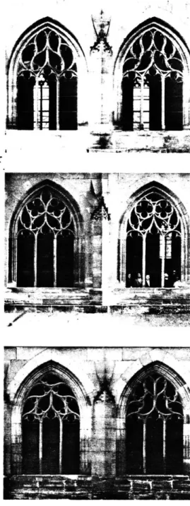
FIG. 1.2 GOTHIC CATHEDRAL WINDOWS, from Gerstner, Designing Programmes
7
circumstances". 'To demonstrate the
application of this idea, Gerstner uses a set of windows from a Gothic cathedral. (fig.
1.2) Each window is a "design in itself based on an exact program of constants and variants". He elucidates the program:
"The material and execution are prescibed; the dimensions, outlines, including the vertical tripartition up to the springing of the arch. here are 16 different
ornamental patterns to be designed in the triangle of the arch and they must be related from the following points of view: the profiles of the lines and the joining together of the bundles of lines are in principle all alike- the tracing of the lines must be adapted organically to the outline and also to the vertical
tripartition- the lines meet either at right angles to each other (or to the periphery) or run into each other at 0 degrees- there must be no residual forms; that is, each line must form a
self-contained pattern on two sides."(1)
FIG. 1.2 cont.
(1) Karl Gerstner, DESIGNING PROGRAMMES,
p. 7
formally complex variety of solutions to the single problem of dividing the shape. A
computer carving system would have the capacity to facilitate the developnent of similar programs for formal solutions relevant to the tasks at hand (visual, tactile, acoustic, ect.) . And since objects can function simultaneously on different levels, (as decoration, as structure, as a medium of direct or indirect communication) , the developnent of a piece might involve the application of a sequence of programs or the
interaction and contention of a number of program requirements.
Various programs will be at hand for the design of these surfaces. Some of these programs are intended to be of general usefulness: basic programs to input depth information that can be used to generate a wide variety of shapes. Others will be
idiosyncratic, special purpose programs of limited application: a computer
representation of a specific icongraphical program, for example. In short, the system's programs would be a reflection of the range of a user/artist's continuing concerns for
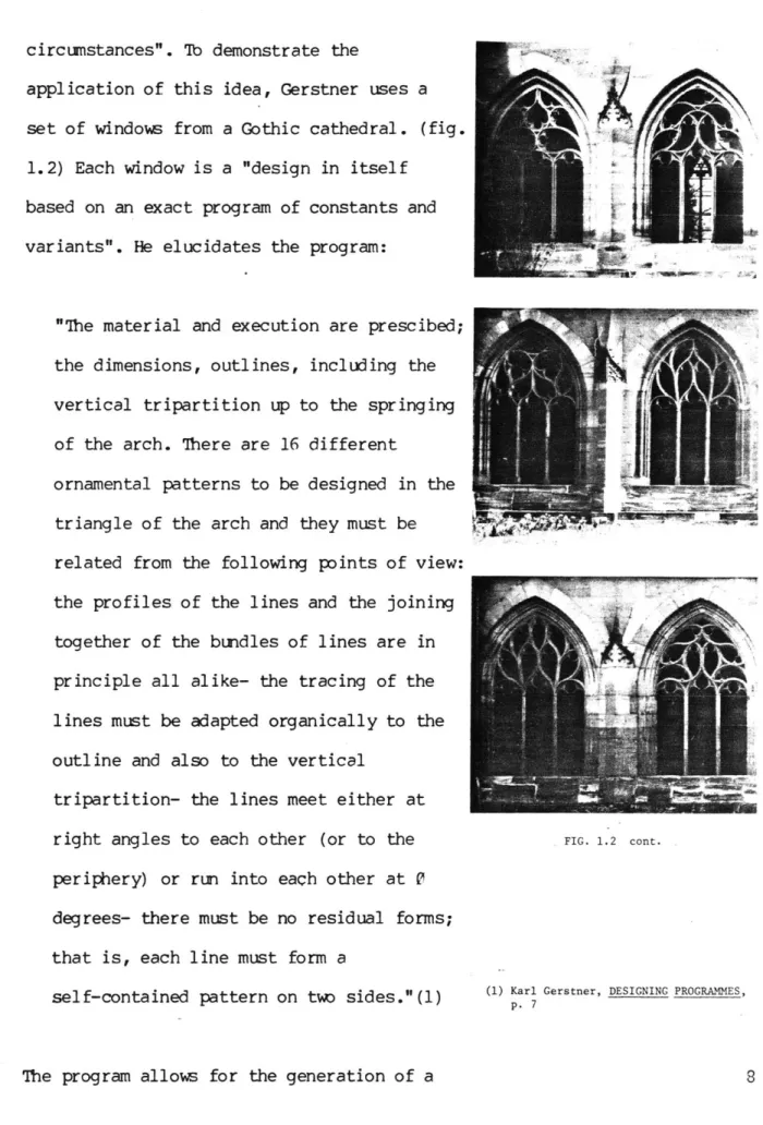
FIG. 1.3 ICONOGRAPHICAL PROGRAM FOR
A MEMORY IMAGE, Rombech, "Gramatica"
and key, from Yates, The Arts of Memory
creative problem solving. The computer representation of form follows a common
format established to simplify the
manipulation of surface data, the generation of displays from that data, and the use of that data in the carving process.
MODELING: A model is a partial image. The assumption in modeling of all sorts (even with a child's toy automobile, for example)
is that if one's image is good enough, its behavior will tell us something important about that of which it is an image. It
follows that the higher the quality of the image, the greater the detail, the more informative will be its behavior. Models are predictive of their subjects, but the
development of a model depends on
observation of the object or process (or similar objects or processes). Thus, the use of models in design involves a circular
procedure of development, with the model informing its subject and the subject, in turn, responding to the adequacy or. inaccuracies of the model. The limits are practical and economic; there is no reason
necessary for its predictive function.
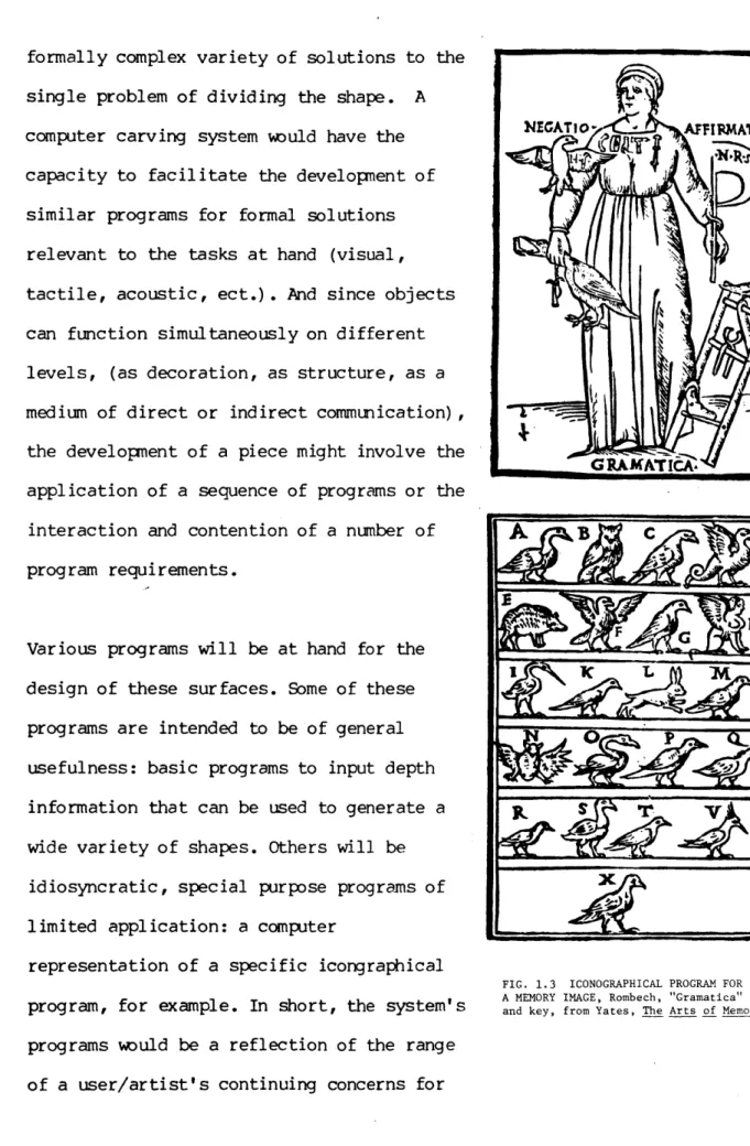
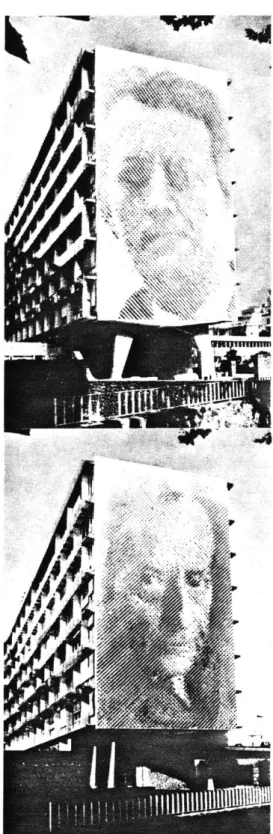
Roland Baladi used a simple model for the sun's movement: he constructed an array of protrusions from a wall, which cast shadows at certain times of day.(l) (fig. 1.4) He could place two images so that each was
revealed or hidden, as the sun moved across the sky. A more complex model might make it possible to design surfaces whose appearance and meaning change continuously through the day and throughout the year.
In a sense, the data describing the surface of the object and a display of that surface data could be considered models for a carved piece. The success of the system depends to a large extent on the accuracy of these representations. However, the system will also contain models in a more dynamic sense, as programatic aids to the design of objects to be placed in a real environment.
Appropriate possiblilities might be for models of environmental conditions: for
sunlight, shading and the movement of shadows; for rain flowing across a surface and collecting in the hollows; or for the
Aw
FIG. 1.4 BALADI'S BASSORILIEVO SOLARE, from Domus, April 1979
(1) "Bassorilievo Solare" from DOMIS 557
April 1976, p. 50
acoustic properties of surfaces. Models for structural necessities, where reinforcing might be needed, could be useful as well.
his kind of approach could make possible the interactive design of not only the formal elements, but also of dynamic and environmental elements. Displays of events of long duration (the sun's movements) can be sped up. Events of short duration (a drop of water falling) can be slowed down.
I
a-120 140 160 180
SOLAR AZIMUTH
420
NORTH
FIG. 1.5 BENNET SUN ANGLE CHART (partial)
12 South 180 I1 jTL:! -I-I I I Loor I i OF L.001, 1 1! j . L 2 4 L 101 A 21 AA. r i of q-ff 1 z X 1! 1 1 A, I / 11! 1 V '! -w., F L F OF F--([
L
I.111
it-] F4
F---YI
K,
~
r 'r If I A.1.2 IMPLEMENTATION
The first step in the development of this system involved several tasks. First, the plotter had to be modified to carve the
large foam blocks, (4' x 4' x 1' was the size decided upon) , and still be able to quickly change back into a painting machine. Therefore, another axis (z) was constructed on which was mounted a router and cutting blade. This z axis assembly was mounted in place of the airbrush unit's counterweight on the y axis of the plotter. The whole plotter, which had previously been bolted to the wall, was placed on a pair of tracks perpendicular to the wall. Pushed all the way in to paint, it can also be pulled out varying distances to carve foam of different thicknesses.
Second, the basic programs for the design of surfaces had to be written. These programs were formulated to take advantage of the existing hardware and graphics software as much as possible. Three methods were
explored:
curved surfaces.
b. a "painting" approach where areas are
drawn on the video monitor with their depth values represented by color.
c. the use of the digitizing camera as an input device, wherein levels of grey are interpreted as depth.
It is important to note that, as the system was never intended as a reproductive tool, the ability to directly input three-d data was not a central part of the system. In the future, however, it may be desirable to add some kind of three-d input device.
In addition to the three methods outlined above, various utility programs were written to compress or expand the range of depth and to produce data for molds by transforming depth images into back-to-front mirror
images.
hird, an examination of various ways of representing three-d on two-d video screens had to be made. The objective was to find which display methods would best enable the
user to monitor the manipulations made on the surface and to preview the appearance of
the carved piece. A shaded surface algorithm was implemented and is compatible with a partially completed shadowing algorithm.
Fourth, programs had to be written to drive the plotter. Various strategies to speed up the process were tried with 1/4" and 3/4" cutting blades.
In addition, the casting of several pieces in concrete was planned, but lack of time made it impossible to get beyond initial explorations of the possibilities of the carving device on a few foam pieces.
1.3 PRECEDENTS
The system bears a family resemblance to numerical control milling machines.
Numerical control is a well developed field with its own languages. The machines are heavy, expensive, accurate, and optimized for working on heavy materials in production situations. An approach to three-d
representation more closely related to this project can be found in the work of A.R. Forrest at Cambridge University. He has built a series of machines for carving three-d foam models. (1) (figs. 1.6, 1.7) Many of the features of these machines are repeated in this system: the connection to a computer graphics system, the univalue
surface with respect to the z axis, and the use of stepper motors on three axis, as well as their early problems with speed and dust removal. Forrest views his machines as
computer peripherals attempting one solution to the problem of computer representation of three-d objects.
The characteristics evolving from its intended function as an environmental and
FIG. 1.6 FORREST, SHIP HULL
FIG. 1.7 FORREST, AIRCRAFT WING WITH
NACELLE FOR UNDERCARRIAGE
(1) A.R. Forrest, "A Computer Peripheral
for Making Three-dimensional Models", from AUTOMATISME, Juin-Juillet 1974
p. 347-351
9 bits (about 0.1" per picture element). In the future, hardware changes probably will be made to increase the size of the spray painted image while retaining the
interactive graphic capabilities of the current system. Ihis increase in size (to 18' x 30') could also be translated into a large increase in the x and y resolution of the carved image.
2.0 MACHINERY
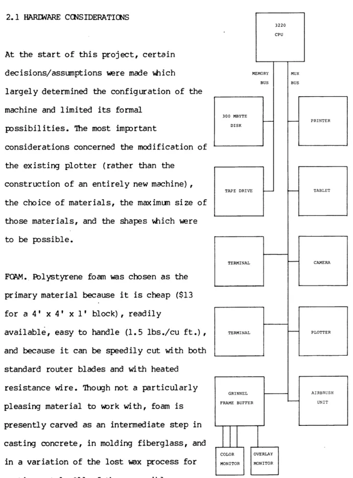
2.1 HARDWARE CCNSIDERATIONS
At the start of this project, certain decisions/assumptions were made which
largely determined the configuration of the machine and limited its formal
possibilities. The most important
considerations concerned the modification of the existing plotter (rather than the
construction of an entirely new machine), the choice of materials, the maximum size of those materials, and the shapes which were to be possible.
FQAM. Polystyrene foam was chosen as the primary material because it is cheap ($13 for a 4' x 4' x l' block), readily
available, easy to handle (1.5 lbs./cu ft.), and because it can be speedily cut with both standard router blades and with heated
resistance wire. 'hough not a particularly pleasing material to work with, foam is
presently carved as an intermediate step in casting concrete, in molding fiberglass, and
in a variation of the lost wax process for casting metal. All of these possible
applications for this system would be
300 MBYTE DISK TAPE DRIVE TERMINAL TERMINAL -- PRINTER -- TABLET CAMERA ~ PLOTTER
FIG. 2.1 HARDWARE ENVIRONMENT
interesting to explore.
SIZE. The maximum area over which the
plotter can scan is about 6' x 8'. Since the foam is available in 4' x 8' sheets and the format of the Grinnel display is square, the natural size in the x and y dimensions is 4' x 4'. This means that each pixel in the
Grinnel corresponds to a .094" square on the carved foam.
The maximum depth to which the machine can cut is twelve inches, a somewhat arbitrary decision based on calculations of how far the cutting blades can be extended from the motor without excessive vibration or
wobbling, and the speed at which the cutting head can be pushed forward and backward to
follow discontinuities (like sharp edges) in the piece being carved. Since, in its
present state, the machine has to make multiple passes to get down to the final
surface, time considerations have meant that only 5.5" of the depth capability has been used so far.
THIS PAGE IS PURPOSELY BLANK
of as an extension of the large airbrush painting project. The modification of the existing plotter, as opposed to the
construction of an entirely new device, was one of the initial assumptions. The elegance transforming such a machine quickly from a painting device to a sculpting tool was appealing. This modification also saved space in a cramped situation, and it saved large amounts of time and money that would have been spent designing and building a prototype device.
SHAPE. Limiting the carving apparatus to cutting in relief is related to the use of the video frame buffer as the medium for design and storage of image information.
Each point on the screen can hold only one depth or z value. This restriction also greatly simplifies the mechanical
functioning of the device, because any swiveling or turning of the cutting head is
unnecessary, as is the calcutation of clearances for fourth or fifth axes.
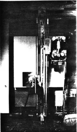
2.2 THE PLOTER
The carving device built for this project rides on an x-y plotter built for a large scale painting application.(fig. 2.2) This plotter consists of a 12' long aluminum I-beam bolted to the wall about eight feet from the floor. Cn the upper channel of this I-beam is a round way on which the x axis carriage slides. This carriage is moved by a stepper motor mounted at one end of the beam. The motor turns a ball screw in a nut fixed to the top of the carriage.
Hinged from this carriage is another I-beam. On this vertical I-beam are mounted two pairs of roundways on which travel the painting device and the painting machine counterweight. Both these mechanisms are attached to a chain mounted on the back of the vertical I-beam and are driven by a stepper motor turning the top chain sprocket. At the bottom of the vertical beam is a piece of aluminum with a roller bearing at one end.(fig. 2.3) This bearing rolls along
the wall and is adjustable to keep the bottom of the y axis parallel to the wall.
FIG. 2.2 PLOTTER, Airbrush unit on the left, carving device on the right
FIG. 2.3 BOTTOM ROLLER
The resolution of the x axis is .0125"/step and the y axis is 235"/step.
This plotter was modified for carving by removing the horizontal I-beam from the wall.
A pair of brackets were made and bolted to
the wall at both ends.(fig. 2.4) These
-brackets support roundways on which the I-beam slides, enabling the whole machine to be positioned against the wall, in its
previous location, to paint. 'b carve, the machine can be pulled out from the wall and adjusted so that the cutting blade, even when fully extended will not hit the wall or jam against the clamps holding the foam.
'Ib hold the foam for carving, a sheet of pegboard is mounted via bolts embedded in the wall. On the pegboard are two 1' x 4' pieces of wood which clamp the piece of foam at the top and bottom. Each wood strip
contains about a dozen small spikes to grip the foam securely.
FIG. 2.4 WALL BRACKET supporting plotter on a sliding bearing
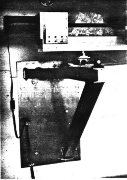
2. 3 THE CARVING MACHINE
In place of the comnterweight on the airbrush plotter, a carving device was attached.(fig. 3.5) The carving device has
two- 26" roundways on which a sliding plate rides. A 12 1/2" long rack is mounted on the lower edge of the plate. Ihis rack is driven
by a 3/4" pinion. The pinion shaft extends
through a hole in the mounting plate and is coupled to a stepper motor. The motor turns
200 steps per revolution which, means that a step will move the sliding plate forward or back
FIG. 2.5 CARVING MACHINE
.012".
A small pnieumatic die grinder motor, which
replaced a one horsepower electric router that was too noisy and too powerful to be cutting foam, is mounted on the sliding plate. The motor is coupled to an extended cutting blade assembly.(figs. 2.6, 2.7) his assembly consists of a 1/4" shaft 12" long mounted in a .5" O.D. steel tube. A
miniaturne ball bearing in the far end of the tube keeps the shaft from vibrating
excessively at the 25,000 rpn free running
NEXT PAGE: FIG. 2.6 PETER LINDENMUTH AND
ROBERT FAUGHT, DESIGN NOTES FOR EXTENDED
CUTTERS
Zfrzzzz~7
-'s/N '~ ,2'7'970
N
/1 25 2S~Oe0
kA rQ~ 1~ Z-PIP Owl',speed. The router blade is attached with adhesive into the end of the shaft. The tube
is clamped firmly to the sliding plate and can be unclamped to change cutting blade assemblies. Three of these cutting blade assemblies have been made with different diameter blades (3/4", 1/4", and 1/16") . Because the blade extends from the motor, sharp edges can be carved without concern that the bulk of the motor will ruin the piece.
FIG. 2.7 EXTENDED CUTTING BLADE
2.4 CUI'TING S'RATEGIES
The control of the cutter as it
moves
through the foam is of major importance,
since this is the final and most basic
determinant of the appearence of the piece.
Che goal is to make the carved piece conform
as closely as possible to the data. However,
it is
perhaps equally important to explore
possibilities for the interpretation of the
data by using different cutting bits in a
variety of ways. The variables that are
being examined here are the size of the
cutters (3/4", 1/4", and soon 1/16") and the
degree of overlap on parallel passes. The
limiting factor in these experiments has
been speed;
and various strategies were
explored to get maximun detail in a minimun
amount of time. These are only preliminary
investigations.
Further hardware changes
will reduce the time necessary to reasonably
carve a piece. These hardware improvements
will make possible a wider variety of and
deeper exploration into carving methods.
All the cutters used so far are cylindrical
in shape, so their flat ends are ideal for
FIG. 2.8 DEEP CUTTING WITH NO OVERLAP, 3/4" BLADE
FIG. 2.9 SMOOTH CURVES WITH NO OVERLAP,
3/4" BLADE
cutting flat surfaces. In addition, they precisely cut vertical edges in the
direction of the scanning across the piece. However, when the blade has to move up or down in its scan across the piece, it leaves
a semi-circular pattern with excess "tails" equal to the radius of the cutter. This pattern is most noticable in deep edges perpendicular to the vertical scanning direction.(fig. 2.8) This pattern may be desirable or acceptable on pieces which have
FIG. 2.10 DEEP CUTTING WITH 50% OVERLAP, no deep edges.(fig. 2.9) The "tails" can be 3/4" BLADE
minimized by overlapping the cuts on
successive passes.(fig. 2.10) Men each pass overlaps the last by half, it doubles the time it takes to carve the piece, but reduces the excess to about an eighth of what it is with no overlap.(fig. 2.11) (The formula is: excess = 1-(.5 x/4-d) , where d
is the distance from cut to cut and both d and the excess are expressed as a percentage of the radius of the cutter.)
FIG. 2.11 COMPARISON OF EXCESS, top- no overlap, bottom- 50% overlap
In cutting 4' x 4' blocks, 3/4" dia. blades are eight pixels wide and 1/4" dia. blades are 3 pixels wide. Before each pass a sort
FIG. 2.12 SMOOTH CURVES WITH 50% OVERLAP, 3/4" BLADE
FIG. 2.13 SMOOTH CURVES WITH 50% OVERLAP,
3/4" BLADE
under the cutter at any point in the traverse across the piece. 'This means that the cutter should never remove any of the surface specified in the data. If it has to err, it will err high. 'he sorting process also makes it possible to remove the mass of material with large blades and to do single passes with smaller blades.
FIG. 2.14 HARD EDGES WITH 50% OVERLAP,
1/4" BLADE
FIG. 2.15 HARD EDGES WITH 50% OVERLAP, 1/4" BLADE
2.5 FUI'URE IMPROVEMENTS
In the near future, several improvements will be made to the machinery. The first will be the construction or adaptation of longer cutting blades. At this time, both the 3/4" and the 1/4" blades are standard wood router blades 5/8" long. 'Ihis means that multiple passes must be made to get rid of material above the final surface of the piece,
resulting in incrediably long times to cut moderately detailed pieces (up to nine hours) . A blade 3" long could cut the time
by at least four times.
The Perkin-Elmer 3220 CPU is being used to generate pulses to move the three axes of
the plotter, so that a large amount of computer time is dedicated to low level
driving chores. In addition it is very difficult to accelerate or decelerate one axis while moving another axis. A
microprocessor or microcontroller is planned to take over the pulse generation tasks.
A larger more powerful waste removal duct is necessary and is also planned.
3.0 DESIGN & DISPLAY
3.1 THE USE OF THE FRAME BUFFER
The design and display methods used in this project make use of various features of our video frame buffer, a Grinnel GMR-27. A frame buffer is basically a memory which stores a displayed image as a set of intensity values. The video screen is divided into a 512 x 512 grid and for each of the resulting 262,000 pixel elements or pixels there are stored 27 bits of data. Fbr
full color graphics, these bits are usually allocated so that eight bits describe each of the intensities of red, blue, and green. The remaining three bits in each pixel are
used for the superimposition of various kinds of graphic information over the color picture. 'Ihe information stored in each pixel location is read and passed to a monitor every thirtieth of a second to maintain a steady picture on the screen. In between the times the pixel memories are being read by the display, they are available
to be read from or written to the host
computer. This is how the image is modified. NEXT PAGE: FIG. 3.1 PARTIAL DIAGRAM OFTHE GRINNEL FRAME BUFFER
The Gr innel has several features that were
TO CPU
EIGHT BIT MEMORY CHANNELS
(RED) (GREEN)
OVERLAY PLANES NINE
(BLUE)
EIGHT TEN
LOOK-UP TABLE MUX
LOOK-UP TABLES
LOOK-UP TABLE SELECT
OUTPUT MUX
35
OUTPUT TO COLOR MONITOR
III
V 77
useful in this project.(fig. 3.1) There are three- ten bit by eight bit lookup tables which use the data stored in the eight bit memory channels plus two of the overlay planes to index a table of eight bit intensity values. Since these tables are loaded independently of the memories, color can be assigned arbitrarily to memory values. There are also a number of clamps and
multiplexers which can be used to change the configuration of the data paths from memory, through or around the lookup tables, and to
the output amplifiers. Another feature that proved useful was the separate video outputs on the overlay planes. This meant that a high-contrast black and white monitor could be run from the Grinnel, in addition to the
full color monitor.
3.2 GRINNEL CCNFIGURATION
The Grinnel was made for the display of high quality color images. However, its
versatility makes it possible to apply some of its capabilities to the task of three-d
imag ing .
What makes it so useful is the limitation of the mechanical part of the cutting machine to three axes of movement. The fact that the surface is univalued with respect to the z axis (no undercutting being possible) means that a two-d array of depth values will describe the surface completely. The frame buffer is a convenient 2-d memory
organization and is ideal for the storage and manipulation of such an array, since it
is not storing "color" but numbers describing color intensities.(fig. 3.2) Allocating 16 of the 27 bits of each pixel
(the red and green channels) to depth information has several implications:
512 x 512 DISPLAY 0 BLUE 0 0 o0 0 0 GREEN 1 1 GREN I I 0 0 .0 o 0 0 0 0 0 0 0 0 I 1 0--- -0 1OR ll BIT -- - CUTTING DATA OVERLAYS 0 16 BIT o DEPTH CHANNEL 27 BIT PIXEL VALUE
FIG. 3.2 REASSIGNMENT OF GRINNEL MEMORY FOR THREE-D APPLICATIONS
1. The depth data stored in this way becomes available for real time interactive
manipulation, with speed comparable to
two-d graphics applications.
2. Both primitive and complex two-d graphics routines can be directly applied to the task of three-d imaging. A square drawn in the green and red channels might become a cube
depending on its "color" value. Three-d images can be saved and loaded from the magnetic disc into the Grinnel memory as if
they were color images. This compatability greatly simplifies the task of developing a
three-d system.
3. The higher eight bits (the blue channel) and the overlay planes are available for display of information about 'the surface. The data in this display can be a realistic shaded surface picture calculated at the same time as the depth info. Both can be written into the Grinnel with one write instruction. Ordinarily, the display, since
it is in the blue channel, would be blue. But, by directing the blue memory channel to all three lookup tables, and loading the tables with appropriate values, a 256 color display can be generated.
4. Since the carving machine has a z axis resolution of 10 bits (.012"/step) in full step mode and 11 bits (.006"/step) in half step mode, there are five or six extra bits available in the 16 bit Grinnel depth
channels. These will be used in the future for the generation of a shadow display using a "z buffer" algorithm (1). Three of
these bits will be the most significant depth bits and will allow for the rotation of a representation of a 4' x 4' x 1' block to any angle to calculate the sun angle view. (Since 10 bits are needed for the l' depth, three more are needed for the 5'9" maximum diagonal.) The other bits will be used at the less significant end to provide a higher precision depth value which, though not used by the carving machine at this time, will reduce the quantitazation error
in the shadowing calculations.
5. Various control functions to govern the carving machine could be stored in the
overlay planes above the corresponding depth
(1) L. Williams, "Casting Curved Shadows on Curved Surfaces" from COMPUTER values.
They
would be accessed at the same GRAPHICS, SIGGRAPH, August 1978p. 270
time as the data.
6. The depth information of smooth curves, when viewed in the normal configuration, is a kind of dizzy moire pattern. The less significant bits of the depth information
fall in the more significant bits of the red channel, while the more significant bits of
the depth information fall in the less significant bits of the green channel. By directing this information to properly loaded lookup tables, meaningful contour maps of the surface can be directly and
instantaneously obtained without calculations using the data.
3.3 DESIGN
Three basic programs for the design of surfaces have been written: an application of b-spline methods for the generation of smooth surfaces, a program for the
interpretation of photographically
digitized images into depth information, and a program for "painting" in depth.
All the programs are operated from the work
station shown in figure 3.3. It is equipped with a terminal, a graphic tablet, and two
monitors: one a color display and the other FIG. 3.3 WORK STATION a black and white display connected to
overlay channel eight.
The spline program shows the first traces of the dynamic modeling mechanism applied to environmental elements. It allows for a
shading algorithm (1) to be applied to
the surface information to generate a shaded image of the surface with the sun at a given chosen angle. This display is rather crude,
it needs to be smoother and it does not show (1) Newman and Sproull, PRINCIPLES OF
INTERACTIVE COMPUTER GRAPHICS,
p. 389-395
shadows except where the surface features shadow themselves. It is, nevertheless,
surprisingly accurate as a comparison of photographs of the shaded display and of the piece will show. (figs. 3.22, 3.23)
The photographic and painting programs are used in the design of a piece as a basic demonstration of the interaction of multiple programs on a single surface.
3. 3. 1 B-SPLINES
The basic program for the design of curved surfaces uses a geometric technique known as
B-splines. Its mathematical basis (1) and algorithms for implementation (2, 3) are well documented-. The technique uses a set of "control points" to which a blending
function is applied. This blending function means that an area on the curved surface will be influenced by the position of the control points nearest that area. Each control point exerts a kind of
gravitational "pull" on the surface. Thus the positions of a small number of control
points can determine the shape of a complex surface.
Fig. 3.4 shows the relative influence of six control points on a third order curve. At either end the blending function considers only one point so, the curve will touch those points. At all the other points the curve is being tugged at by three control
points. Increasing the order of the curve will increase the number of control points which affect any point on the curve, with a
FIG. 3.4 (from Gordon and Riesenfeld)
I1-* 1 * (1 2 (ii) linear 1/2 0 1 2 3 0 1 2 3 4
(iii) quadratic (iV) cubic
FIG. 3.5 (from Gordon and Riesenfeld)
(1) C. DeBoor, "On Calculating with
B-splines" from JOURNAL OF APPROXIMA-TION THEORY, 6, 1972, p. 50-62
(2) Gordon and Riesenfeld, "B-spline Curves and Surfaces" from Barnhill and Riesenfeld, COMPUTER AIDED GEOMETRIC DESIGN, p. 293-310
(3) Newman and Sproull, PRINCIPLES OF INTERACTIVE COMPUTER GRAPHICS, p. 320-325
corresponding change in the shape of the
curve. The relative pull of a control point
on different orders of curves is shown in
fig. 3.5. The lower the order, greater is
the effect of the control points position on
a narrower area of the curve. And the higher
the order the more blending will occur and
the smoother will be the curve.
The program for the manipulation of the
position of the control points uses two
monitors. 71o start, a 4 x 4 grid is
displayed. On one monitor is a view looking
at the grid along the z axis (fig. 3.6), on
the other is a view of the grid from a
position 45 degrees above the horizon (fig.
3.7).
The user
selects one of these views and with
the tablet .can choose a point and move it
around the screen. With the top view
selected he can change the position of the
point relative to the x and y axes. This top
view is normally used for stacking points in
certain areas to locally reduce the order of
the curve. This creates discontinuities or
edges on the surface. With the angled view
FIG. 3.6
FIG. 3.7
FIG. 3.8
selected he can change the position of the
point only in relation to the z axis.(fig.
3.8) As the changes in position are made,
the new locations are entered in a list of
the points' coordinates stored in a data
segment.
With the 4 x 4 grid of control points the
FIG. 3.9
user can make gross changes in the surface.
By pressing a button on the tablet, a
preview of the surface is
generated on the
top monitor (this takes about 5 seconds).
Points moved up create bulges in the surface
and points moved down create depressions.
(The preview shown in fig. 3.9 is a third
order curve.)
FIG. 3.10
To
allow finer surface features to be
created the user can quickly increase the
number
of control points. A linear
interpolation is done between the existing
points and the grid is increased to 7 x
7.-(figs. 3.10, 3.11) The angled view can be
spun
around
to permit a more accurate
reading of the grid of points in space. his
FIG. 3.11is useful since confusion may arise, as the
grid resolution increases, because of the
the lack of hidden line removal in the display.
The process of subdividing the grid of
control points can be repeated twice more to make grids of 13 x 13 (figs. 3.12, 3.13) and
25 x 25. Finer and finer distinctions are
possible with each increase in grid resolution.
Figs. 3.14 through 3.22 show the final steps in the design of a surface.
Fig. 3.14 is the top view. Points are moved to vary the effective order of the curve across the surface creating a variety of shapes and edges.
FIG. 3.12
FIG. 3.13
FIG. 3.14
Figs. 3.15-3.18 are displays of the control points and preview curves from two different angles. Although confusing in the
photographs, it was still possible, by rotating the grids and drawing the preview curves, to see where points were located in the represented space.
FIG. 3.15
FIG. 3.16
FIG. 3.17
Figures 3.19 and 3.20 show shaded surface views with the light source at different angles. In these displays a spline surface with a 50 x 50 resolution was generated from
the control points. The image is drawn from back to front to eliminate the need for hidden surface removal. These images took
thirty seconds to draw.
FIG. 3.1
Figure 3.22 shows a shaded view of the surface. The display actually uses just the blue channel of the Grinnel. By directing
the data in that channel to all three video output amplifiers, the actual depth
information is made invisible. The depth data (made visible for fig. 3.21) is
generated from the spline curve at the same FIG. 3.19
time as the shaded image. It is this depth data which the carving machine uses in cutting the piece.
FIG. 3.20
48 8
Fig. 3.23 shows a sample piece carved from the data in figure 3.21. It was carved with a 3/4" cutter with 50% overlap of each vertical scan. It took approximately eight hours to carve.
FIG. 3.21
FIG. 3.22
FIG. 3.23
3.3.2 PHOTOGRA1IPIC INPUT
Two programs were written to take advantage of the possibility of interpreting
photographic images as three-d forms. The first program takes an eight bit color channel and transforms the grey tones into depth values in the standard 16 bit depth
format. These depth values range between a high bound (white) and a low bound (black) .
Since the piotographic image does not contain three-d data except by inference, this process involves a level of abstraction
in the interpretation of gradation of grey tone as change in depth. The second program
takes an eight bit color channel and sets the depth value to a high bound if the tone
is above middle grey ('1000000'b) and sets it to a low bound if the tone is below
middle grey. Figs. 3.24-3.26 show this second program applied to an image photographically digitized from a type specimen book.
Figure 3.24 shows the digitized page. It is a black and u4hite image.
In figure 3.25 the eight bit green channel was
FIG. 3.24 FIG. 3.25 FIG. 3.26 50
-M
CDEF
LMNOF
TUVWX'
abcdefg
CDEF
ILMNOF
T
VWX'
abcdefgl
processed into the sixteen bit depth format. The high bound was 410 (about 5") and the low bound was 235 (about 4") .
Figure 3.26 shows a cross section of the depth of the surface at a horizontal line through the middle of the letters. (the cursor is visible in the verticle stroke of the "b"
indicating the position of the cross section.)
3.3.3 PAINTING
Since the surfaces being designed are
univalued with respect to the z axis, and
since the depth information is being stored
in what are normally color channels, it is
possible to choose color values which
correspond to depth levels and to write
areas having those values to the Grinnel.
his "painting" process is exactly the same
as that used in two-d color graphics. The
graphic tablet is used to indicate position
on the video screen to the computer. Squares
are drawn in those positions so quickly by
the Grinnel that moving the tablet stylus
produces lines or continuous curves. The
"brush" has the same width as the squares
being drawn.
In fig. 3.26 the upper case letters were
painted over with a brush of the same value
as the background, thereby erasing them.
In fig. 3.27 various lines and curves were
drawn over the image in fig. 3.26. (The tones
represent the actual depth data, so they
signify different depths, but not relative
FIG. 3.27
depth values.)
Fig. 3.28 is the final piece. It was carved with a 1/4" cutter with the vertical scans overlaping each other by 50%. It took six hours to carve.
FIG. 3.28
3.4 CONTOURS
The depth data, when displayed in the normal
manner (fig. 3.21), is not very useful.
Since the less significant bits of the depth
data fall in the more significant bits of
the red channel, they appear as tiny
concentric lines. The more significant depth
FIG. 3.29
bits fall in the lower part of the green
channel and are too dim to be recognizable.
However, since each depth has a unique value,
it is possible, by using the color lookup
(
tables, to assign a color to each value.
Using the depth values as indexes to
properly assigned lookup tables, topographic
maps of the surface can be generated.
hese
maps can be color-coded in innumerable ways. FIG. 3.30
Since there are no calculations involving
the depth data, these maps can be displayed
almost instantly.
Fbur possiblities were explored. Some may be
more useful in specific situations than
others.
FIG. 3.31
a.
The
first map (fig. 3.29) uses the most
significant bit in the red channel (bit 5
in
the 10 bit carving data) to generate black and %hite lines. This is slightly better than the raw data.
b. A bolder version of "a" (fig. 3.30) which
uses bit two in the green channel (bit 7 in the 10 bit carving data).
c. A map (fig. 3.31) that uses the lower five bits in the green channel (bits 6-10 in the carving data) to generate a 32 step grey scale where black is the lowest level and white is the highest level.
d. A map (fig. 3.32) that uses bits two
through five in the green channel to
generate a 16 step grey scale. This sixteen step version seems to better convey the shapes of deeper pieces than the 32 step version.
All these contour programs direct either the
red or the green channel to all three of the lookup tables, and after loading those
tables, they enable the lookup table select switches.
FIG. 3.32
3.5 TRANSFOMATIONS
Four programs were written for transforming entire images. The figures shown use a sixteen step contour map with light greys indicating high places, dark greys
indicating low places. A program called "scan" was called to give a cross section of a horizontal line about halfway up. the
screen. The effects of the transformations described are visible on both the cross section and on the greys in the contour map.
COMPRESS looks for the high and low bounds
of the existing image (fig. 3.33) and asks for new high and low depth boundaries. It then compresses the depth values linearly to fit within those bounds. (fig. 3.34)
INVERT takes the image (fig. 3.34) and turns it inside out (fig. 3.35). The places which were once high are now low and vice versa.
MIRROR takes the image (fig. 3.35) and turns it around so that uhat was on the left is on the right and vice versa. (fig. 3.36)
FIG. 3.33
FIG. 3.34
FIG. 3.35
MOLD does the same things as compress, invert and mirror but in one step. It is useful for making molds for surfaces.
FIG. 3.36
3.6 PRCBLEMS
It was assumed that the power of the
computer as an extendable, interactive tool would overcome the untactile and
unsatisfying nature of the design of sculptural shapes on a two dimensional display. The
goal of this project was not to eliminate
those negative aspects caused by this distancing, but to provide other capabilities that would minimize their importance. In the current primative state of the system, they still loom large.
4.0 PROGRAMS
The following pages contain an alphabetized list of the programs written for this
project. The name of each routine is followed by:
1. A brief description of the program.
2. The format for its correct use (the declare and call statements, if applicable).
3. A list of the programs it calls, if they are not installed in the systems or graphics libraries.
4. A list of the programs which call the routine.
All these programs can be found in the
directory >u>fot.
The programs dealing with machine functions are in subdirectory "real". The names of the various carving programs end with "pass".
(dpass,npass,onepass,qopass qpass) . The programs to adjust the speeds of the axes are "rampant" and "zinc".
The programs for the design of surfaces are in subdirectory "s". 7b manipulate the grid of spline control points call "cs". Then
call "sp50" and "sm50" for the shaded view and depth map, or call "tilt50" and "tms" for the shaded angled view.
Other design programs in subdirectory "s" are:
"cross" for interactive painting in depth, "crunch" and "tcrunch" for tran!9forming
photographs into the depth format, "scan" and "look" for cross sections of
surfaces,
"contour" ,"contour2","contour3" ,"contour4" for generating topographic maps with the lookup tables,
"compress","invert" ,"mirror" and "mold" for doing transformations on entire images.
The programs to change the Grinnel
configuration are in subdirectory "grin". These programs are "lt mux","switch", and "ocolor". From command level, "otest" and "stest" call "ocolor" and "lt mux"
respectively.
This thesis report can be found in subdirectory "thesis
ANOTHER
This routine divides irregular polygons into rectangles and passes each rectangle's
coordinates, plane equations and color to SGROUND.
dcl another entry ( , ,fix,flt,flt,flt,bit(8));
call another (x array,y array,n,ab,ccolor); x_array, y_array are the vertices of the
polygon listed either clockwise or counterclockwise.
n is the number of vertices,
a,b,c is the plane equation of polygon, color is the shade or color of polygon. called by: sm50, tm50
calls: sground
COMPRESS
This routine asks for new high and low bounds and compresses or expands all the depths in the depth map to fit into those bounds.
CCNTOUR
These are a set of routines which load the lookup tables with values and direct a channel of the depth map to all three
tables. They give a kind of topographic map effect. CONTOUR alternates black and white
to indicate depth changes in wide bands. CONTOUR2 uses narrow black and white bands.
CCNTOUR3 uses changes in value from dark (low) to white (high) to indicate changes in level. CCNTOUR4 is the narrow band version of CGNTOUR3. Which program is used depends on the image being displayed. Images which have a small range of subtle changes would best be shown with a program which uses narrow bands. The same program would be confusing when applied to an image with a wide range of depth.
CROSS
This routine allow the user to draw directly with depth values into the Grinnel. The buttons on the tablet are used to select depth values, to draw horizontal or vertical
lines, or to draw free curves.
CRUNCH
This routine is used to convert the grey tones of digitized photographic images into the carving data format. It asks for a high bound, a low bound and whether or not the data should be inverted. The eight bits which make up what is normally the green channel are compressed or expanded so that white is the high bound and black is the low bound and the grey values are in between.
CS
This is the main process for the design of b-spline surfaces. It uses two monitors, the color monitor and one connected to overlay channel eight. CS asks for the order of the preview curve, all the rest of the commands are controlled through a menu and the tablet buttons.
calls: splinep, linev, ocolor, trans, trig
DPASS
Carving program for 3/4" blade. It cuts without overlapping for fast removal of
foam, but with the disadvantage of leaving a rough surface.
calls: nfast, move$calibrate, move $init0, move$x
HQUICK
This is a higher resolution version of QUICK which uses 9 bits but distorts the
relationship between the depth values and the y axis.
INVERT
This routine takes the depth map and inverts it so that the highest part is low and the lowest part is high. It also allows one to specify a new high bound so that the image can be compressed or expanded along the depth (z) axis. This routine is useful in converting an image into a negative mold of that image.
LINEV
This routine is for drawing or erasing lines in an overlay plane without writing over information in the other overlay planes. dcl grin$linev (fix,fix,fix,fix,bit(16),
fix);
call grin$linev (xl,yl,x2,y2,plane,on); xl,yl,x2,y2 are the endpoints of the line,
plane is the overlay plane. on=l to write ones into the plane. on=0 to write zeros into the plane.
called by: cs, splinep
LOOK
This routine asks the user to type in a line number and then displays a cross section of that line in plane eight.
LT MUX
This routine changes the Grinnel lookup table mux. Any combination of the three lookup tables can be connected to one of the three memory channels or the digitizer.
(a=0,b=l,c=2 is the normal mode.) dcl lt mux entry (fix,fix,fix); call ltmux (a,b,c);
(where a,b,and c are the three lookup tables which are equal to channels 0,1,2, or 3. 3 being the digitizer.)
called by: sm50, tm50, tms50
MAKEA
This routine is for making the tables of b-spline blending values. It looks in the directory >u>fot>tables for a segment containing the specified table. If none is
found it makes the table and stores it in that directory.
dcl makea entry (fix,fix,fix); call makea (n,k,s);
n is the number of control points minus one, k is the order of the curve,
s is the number of line segments which make the curve.
called by: splinep, tilt50, sp50
MIRROR
This routine reverses the image so that what was on the left is on the right, and what was on the right is on the left.
MOLD
This routine inverts the image from front to back and left to right in one step. This is the transformation necessary to convert an
image into a mold for that image.
MOVE$CALIBRATE
This routine aligns the cutter at the end of each pass.
dcl move$calibrate entry (fix,fix); call move$calibrate (bias,endlevel);
endlevel is the depth of the cutter at the end of the previous pass,
bias is the depth of the cutter at the beginning of the next pass.
MOVE$INIT0
This routine initializes the 3/4" cutter position on the y axis at the beginning of the first pass of the carving program. The cutter is aligned with the top left corner of the block of foam. MOVE$INIT0 moves it down run+upstepno number of steps.
dcl move$init0 entry; call move$init0;
MOVE$X
This routine moves the horizontal axis. There are 1600 steps/inch.
dcl move~x entry (fix); call move$x (steps);
steps is the number of steps to be moved (positive values move it to the right).
MOVE$Y
This routine moves the vertical axis. There are about 84 steps/inch.
dcl move$y entry (fix); call move$y (steps);
steps is the number of steps to be moved (positive values move it up) .
NPASS
Carving program for 3/4" blade. It executes mutiple cuts down to the proper level and
overlaps the pas'ses across the piece by 50%. calls: nfast, move$calibrate, move
$init0, move$x
OCOLOR
This is a routine to assign colors to the Grinnel overlay planes. Each of the overlay planes is connected to each of the three
switching these connections on or off each overlay can be given one of seven colors or black (off). The colors are coded:
0=black(off) , l=blue, 2=green, 3= bluegreen, 4=red, 5=magneta, 6=yellow, and 7=white. It is also useful for making information
invisible on the main monitor while
displaying it on a monitor connected to the overlay plane output.
dcl ocolor entry (fix,fix,fix); call ocolor (eight,nine,ten); called by: cs, sm50, tms50, tm50
ONEPASS
Carving program for 3/4" blade. It only executes the final cut across the surface. This makes it useful after DPASS to get a piece with finer resolution. It overlaps the passes across the piece by 50%.
calls: nfast, move$calibrate, move $init0, move$x
OTEST
This is for colorizing the Grinnel overlay planes from command level.
calls: ocolor
QOPASS
ibis is a carving program for 1/4" blade. It overlaps the passes by 50% and only
executes the final pass across the surface. calls: qfast, move$calibrate, move
$init0, move$x
QPASS
Carving program for 1/4" blade. 50% overlap.
calls: qfast, move$calibrate, move
QUICK
This routine uses the tablet to create a quick, low resolution (only 7 bits) surface that curves in only the y direction. Useful
for tests. RAMPANT
This routine stores information about the movement of the x and y axis in the data segments "x.curve" and "y.curve". It also computes the acceleration and deceleration curves for the axis. The data is stored in a structure like this:
dcl 1 data based (dp); 2 upstepno, 2 dnstepno, 2 begdelay, 2 enddelay, 2 vmesh flt, 2 hmesh flt, 2 ups(600), 2 dns(600), 2 rpf flt, 2 run;
upstepno, dnstepno are the number of steps to accelerate and decelerate.
begdelay, enddelay are the starting delay value and the minimum delay value (a delay is = .000002 sec.).
hmesh is the starting angle of the curve. ups and dns are arrays of delay values. run is the distance travelled at maximum
speed.
All the other variables are no longer
relevent.
calls: "y.curve", "x.curve"
SCAN
This routine takes a position from the tablet and draws (in plane eight) a
horizontal or vertical cross-section through that point.
SGROUND
This routine takes a rectangle, a plane equation, and a color. It does a linear
interpolation to find all the z values of the points bound by the rectangle. It then writes a rectangular area with this
information into the bottom 16 bits and a color to the top eight bits of the Grinnel. dcl sground entry (fix, fix, fix, fix, flt,
flt, flt, bit(8));
call ground (left, bottom, right, top, a, b, c, color);
left, bottom, right, and top are the sides of the rectangle,
a,b,and c are the plane equation, color is the color or shade of the
rectangle. called by: another
SM50
This routine uses the 50x50 spline curve grid which has been stored in the data segment "points" by SP50. It reconfigures the Grinnel so that the top eight bits are directed to all three output drivers. A ray toward the light source is used to generate a shaded image of the surface in the top eight bits. At the same time a 512 x 512 depth map is generated in the (invisible) bottom 16 bits. The surface can be cut directly from this map.
calls: another,ocolor,lt_mux
SP50
This routine uses the grid of control
points stored in the first part of the data segment "stuff" to make a 50 x 50 array of points on a b-spline curve of a given order.
It stores this array in the data segment "points".
calls: makea, "stuff", "points",
SPLINEP
This routine is used to quickly preview the spline surface while it is being designed.
It draws a 25 x 25 grid in plane eight. dcl splinep entry (ptr,ptr,ptr,fix,fix,fix); call splinep (x_ptr,y_ptr,z_ptr,maxx,maxy,k); x ptr ,y ptr ,z ptr are pointers to arrays of
control points expressed as floating point numbers,
maxx,maxy are the dimensions of the grid of control points,
k is the order of the curve to be drawn. called by: cs
calls: makea, linev
STEST
This is for changing the configuration of the Grinnel lookup table mux from command level.
calls: ltmux
SWITCH
This routine changes the Grinnel video input mux configuration. Each of the three video channels (red,green,and blue) can be
directed toward any of the three video drivers.
dcl switch entry (fix,fix,fix); call switch (a,b,c);
a,b,and c are the output drivers. They can be equal to 0,1,or 2 which correspond to the input channels. (a=0,b=l,c=2 is the normal mode.)
TCRUNCH
This routine is a high contrast version of CRUNCH. It takes eight bits from the green channel of the Grinnel and converts it to the carving data format. It takes high and low bounds and sets pixels equal to one or