OATAO is an open access repository that collects the work of Toulouse
researchers and makes it freely available over the web where possible
Any correspondence concerning this service should be sent
to the repository administrator:
[email protected]
This is an author’s version published in: http://oatao.univ-toulouse.fr/23622
To cite this version:
Delebarre, Corentin
and Wagner, Vincent
and Paris,
Jean-Yves
and Dessein, Gilles
and Denape, Jean
and
Gurt-Santanach, Julien High speed interaction between an abradable
coating and a labyrinth seal in turbo-engine application. (2014) In:
International Joint Conference on Mechanics, Design Engineering &
Advanced Manufacturing (2014), 18 June 2014 - 20 June 2014
(Toulouse, France).
HIGH SPEED INTERACTION BETWEEN AN ABRADABLE COATING
AND A LABYRINTH SEAL IN TURBO-ENGINE APPLICATION
C. Delebarre 1,2, V. Wagner 2, J.Y. Paris 2, G. Dessein 2, J. Denape 2, J. Gurt-Santanach 1
(1) : TURBOMECA, Avenue Joseph Szydlowski,
64510 Bordes, France
E-mail : [email protected]
(2) : Université de Toulouse, Laboratoire Génie de
Production, Ecole Nationale d’Ingénieurs de Tarbes, 47 Avenue d’Azereix, BP 1629, 65016 Tarbes Cedex,
France
Phone/Fax : 0562442700 E-mail : [email protected]
Abstract: The design of gas turbine aims to enhance the
engine efficiency by developing new materials able to work at higher temperatures, or to promote new technologies, fuel management and airflow direction. One solution is the reduction of clearance between rotary parts in turbomachinery air systems. This clearance reduction causes direct interactions in the secondary air system of a turbo-engine when a rotary seal, called labyrinth seal, rubs on the turbo-engine as a result of successive starts and stops, thermal expansions and vibrations. The purpose of the present paper is to study interaction phenomena between an abradable material (Al-Si 6%) and a nickel alloy (718 alloy) during high speed contacts. A high speed test rig has been designed to simulate interactions between labyrinth seals and abradable coatings in similar operating conditions of turbo-engine in terms of geometries, rotational and linear velocities. A series of experiments has been carried out in order to get a first assessment under different turbo-engine operating conditions. Experimental results are presented using visual observations of test samples, quantitative approaches of interacting forces and micrographic observations. This work provides new basic data for a preliminary study of the interaction between a labyrinth seal teeth tips and its casing for turbo-engine applications.
Key words: Labyrinth seal, abradable material, high speed
interaction
1- Introduction
During decades, turbomachinery manufacturers try to find how to save energy by increasing engine efficiency. One way to improve engine efficiency is to control the airflow direction by reducing the clearance between rotary parts in air systems [DE1]. In the secondary air and sealing systems, the control pressure differences and the levels of cooling between modules of the engines are crucial in order to operate the turbine. As a part of dynamic sealing systems, labyrinth seals are used to reduce the loss of high pressure gas within the engine cycle. This special type of rotary seal controls cooling air flow
through the hot section of the engine and maintains pressure balance on the rotor shaft system. They are located on the rotating shafts between the compression stages and are composed of several teeth [DW1].
Nevertheless, reducing the clearance might cause undesirable interactions between labyrinth teeth tips and housing [SG1]. This is also true for successive start and stop cycles, thermal expansions, vibrations and mechanical loadings occurring during engine operation [JT1]. In this case, labyrinth teeth rub into the housing surface and form rub-grooves on it. To avoid undesirable wear due to incursions of labyrinth teeth in the bare metal housing, the insert of a few millimeters abradable material layer was widely recognized as a robust solution. The turbo-engine housing is coated with a sacrificial abradable material (rub tolerant material) sprayed by thermal spraying [R1]. This coating can be composed of metal phase and self-lubricating non-metal phase, which provides a high porosity rate and offers a good balance between abradability and erosion resistance [MB1]. This method is widespread in other turbine-engine applications such as blade tip and compressor housing where extensive researches are conducted to characterise blade-abradable interaction [CT1]. The use of abradable seal to prevent rub interactions encourages aeronautical engineers to characterize the abradable behavior during labyrinth seal interactions and to validate the design choices in the various stages of the engine.
Today, research activities are mainly concentrated on the labyrinth seal behavior in their sealing performance before and after interaction. Many experimental studies (with development of specific test rig) and numerical studies help characterize the effect of interactions on the aerodynamic seal performance, leakage levels generated by the grooves left by labyrinth teeth and the effect on tooth profiles [DP1, CT1, GV1].
coating, very few studies are devoted to understanding the contact. Dowson et al [DR1] and Whalen et al [WA1] developed a full-scale facility based on a grinding machine, to study the behavior of abradable materials (mica filled tetrafluoroethylene (TFE), silicone rubber, aluminium polyester and nickel graphite) in contact with labyrinth seal at relative speed up to 25 m·s-1 and 130 m·s-1 respectively. They performed contact with incursion speeds varying from 2.54 m·s-1 to 25.4 m·s-1 which are defined as representative conditions of labyrinth thermal expansions and vibrations. They established a “good abradability” condition for tested materials by defining a special ratio. Mutazim et al [MH1] introduce an additional condition describing interaction by characterizing the rub-groove geometry of seven abradable materials (aluminium, Al-bronze, Al-Si-polyester, Al-bronze-polyester, Al-Si-polyimide, Cu-Sn-Bi, Cu-Sn-Pb) subjected to labyrinth seal interaction. A specific full-scale test rig was developed and performed under unlubricated conditions. Later, Sulzer Innotec and Sulzer Metco companies [W1] worked closely on the development of abradable materials, by using special test rig adapted to the application of labyrinth/abradable interactions. It consists of an alloy disc that accommodates four continuous seal trips on the outer circumference, a movable specimen controlled by a programmable controller coated with abradable (step length of 0.15 µm), and a heating device (from 25°C to 700°C). The wear behavior is evaluated using the seal strip cutting-edge velocity, the temperature of the shroud segment, the wear track depth and the incursion depth and the video of test.
The present paper describes the results of an experimental investigation carried out to undertake a first assessment of high speed mechanical interactions between a labyrinth seal of 718 alloy and an abradable Al-Si 6% coating. An original test rig is specially designed to simulate these interactions in realistic operating conditions.
2- Experimental protocol
2-1 Test rig description
The experimental device presented in Fig. 1 has been specially designed and developed to simulate and to study operational wear interactions between labyrinth seals and abradable coatings in similar operating conditions as turbo-engine. For that, a 5-axis milling machine UCP600 VARIO from Mikron is used as a test rig and receives a specific experimental device. The 5-axis milling machine has the particularity to be fitted with a special magnetic bearings spindle which allows a maximum rotation speed of 40 000 rpm and maintains the spindle vertically without any mechanical contact.
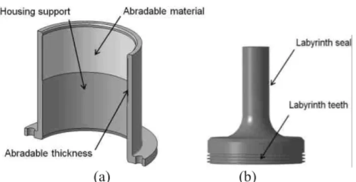
A labyrinth seal, representative of an actual part of a motor shaft section is shrinking on a HSK-50 tool holder instead of a cutting tool (Fig. 2a). The contact is performed inside a special tube sample coated with abradable materials in this inner periphery. This specimen is representative of the housing facing labyrinth seals in the secondary airflow turbo-engine section (Fig. 2b). A diffuser and a base piece precisely fasten
the tube sample coated with abradable on the machine tool table. The diffuser is specially designed to simulate the sealing of the labyrinth seal during operation by pressurizing the entire system. It will allow, for future tests, the measurement of their leakage level and their sealing performance after interactions. In case of sample break during the test, a protective shielding has been designed. The rotation speed of labyrinth seal varies from 0 to 40 000 rpm, representative of typical speed reached by free turbines in turbo-engines, and corresponding to a labyrinth tip speed varying from 0 to 130 m·s-1. Contact between labyrinth seal and abradable is controlled by using capabilities of the high speed milling machine, which gives rise to a radial incursion speed ranged from 0.001 mm·s-1 to 25 mm·s-1. Geometric tolerances of samples and theirs assemblies require a precise control of a clearance of 150 µm between labyrinth teeth tips and abradable coating, according to real engine conditions.
Figure 1: Labyrinth-abradable interaction test rig.
(a) (b)
Figure 2: (a) Labyrinth seal specimen, (b) Abradable coating on housing support.
2-2 Contact geometry
Interactions between labyrinth tips teeth and abradable coating are characterized by a complex contact geometry induced by the incursion of a circular tooth of trapezoidal
section in a tube coated with abradable. This contact geometry evolves during the test according to the incursion depth, as shown in Fig. 3. Nevertheless, the machining precision of labyrinth seal teeth (geometric tolerances, unbalance…), the positioning precision of test pieces and the spindle stiffness (supposed infinite during contact), have an important impact on the nature of the interaction. Once the labyrinth seal precisely positioned in the abradable test piece, the concentricity error is stated to ±30 µm. In addition, for the reasons given above, the use of three teeth labyrinth seal leads to get three different contact behaviors, one for each tooth, with the same test condition. The geometric confinement of the central tooth probably leads to thermal phenomenon during the interaction.
2-3 Contact forces measurement
A special instrumentation has been developed on the rig test to record forces during interactions thought the continuous control current of the spindle magnetic bearings. This continuous control current is performed to maintain the rotation shaft axis in the centre responsive to any change of load (external force, disturbance of a solid rotor imbalance). In our case, interacting forces induced by the labyrinth seal incursion are directly transmitted in the magnetic bearings and compensated through control current signals. These compensated signals are then recorded by a special Matlab toolbox, and processed as contact force signals (Fig. 4). The force measurements are then represented using the norm defined in the following equation:
)² ( )² ( )² (fx fy fz F = + + (1)
Figure 4: Schematic diagram of forces acquisition.
2-4 Test parameters
As mentioned earlier, the labyrinth seal specimens analyzed in this study was made of 718 alloy whose chemical composition is presented in Table 1. It was designed with three circular teeth of 65.8 mm in external diameter. The Al-Si 6% coating was sprayed inside the housing support on a stainless steel substrate. Spraying is realized with a thermal wire flame spray process onto a bond coat approximately ranged from 20 to 150 µm (Fig. 5). The high roughness of the bond coat promotes good cohesion of the deposit. Once coated, the housing support is machined by milling to control the abradable thickness (about 1 mm) which defined the mechanical clearance between abradable coating and labyrinth seal teeth.
Elements (% by mass)
Ni Cr Fe Mo Nb Co Mn Min 50 15 2.8 4.75
Max 55 21 Base 3.3 5.50 1.0 0.35 Material properties :
Tensile strength (MPa) 1310 Yield Strength (MPa) 1110 Elastic modulus (GPa) 206
Hardness (HV150) 370
Density (g·cm3) 8.19
Melting point (°C) 1300 Thermal conductivity (W·m·K-1) 11.2
Table 1 : Chemical composition and properties of 718 alloy.
The main studied test parameters are labyrinth tip speed, rotation speed, incursion speed and incursion depth. A test matrix has been selected to cover various conditions encountered in turbo-engine such as engine vibrations, excessive mechanical loading or thermal expansion. Table 2 shows the test parameters studied in this work. It is important to mention that all the tests were carried out with only one labyrinth seal sample.
Table 2: Test parameters.
Test n° Rotation Speed (Vr) (rpm) Labyrinth tip speed (Vt) (m·s-1) Incursion speed (Vinc) (mm·s-1) Incursion depth (Dp) (mm) 1 37500 130 0.005 0.2 2 37500 130 25 0.2 3 12500 43 0.005 0.2 4 12500 43 25 0.2 5 5000 17 0.005 0.2 6 5000 17 25 0.2
Figure 5: Microstructure in section view of Al-Si 6% coating on stainless steel substrate.
3- Data analysis and discussion
3-1 Analysis of test samples
A first post mortem analysis is performed by a visual observation of labyrinth seal teeth and abradable coating after test. Fig. 6 presents all the rub-grooves left by labyrinth seal teeth on Al-Si 6% abradable for each test parameter.
Figure 6: Images of abradable rub-grooves after testing.
As seen in Fig. 6, different morphologies of rub-grooves are observed according to test parameters. Some rub-grooves present a significant amount of plastically deformed material on both sides of the groove. This is the case for tests at high incursion speed (tests n°2, 4, 6) and for test n°1 at low incursion speed and labyrinth tip speed of 130 m·s-1. Unlike others, rub-grooves from tests n°3 and 5 (low incursion speed and low rotational speed) display geometries that may be qualified as "clear-cut" appearance without positive amount of material. Visual observations of labyrinth seal teeth after test did not show any noticeable changes or severe wear except for labyrinth seal teeth from tests n°3 and 4. Al-Si 6% coating transfer was observed on the top of labyrinth seal teeth, as shown in Fig. 7.
Figure 7: Al-Si 6% transfer on labyrinth seal teeth after test n°3 (Vr = 12 500 rpm, Vinc = 0.005 m·s
-1 ).
Such results suggest that incursion speed Vinc is a significant parameter for rub-grooves morphology. However, results of test n°1 demonstrate the additional influence of the labyrinth rotation speed. To confirm rub-grooves visual observations, accurate profile measurements were carried out with a SOMICRONIC 2C profilometer at the maximum incursion depth area (Fig. 8). Positive heights and negative depths are identified and quantified respectively by Z1 and Z2 values.
Figure 8: Rub-grooves measurement depth, corresponding to the six test conditions.
In most cases, rub-grooves formed on Al-Si 6% were widely deeper than the 200 µm fixed by the maximum labyrinth seal radial incursion. In addition, on each test, the deeper rub-groove corresponds to the tooth which is confined between the others two. This is consistent with the hypothesis of the presence of an additional wear phenomenon within the affected area because of thermal confinement.
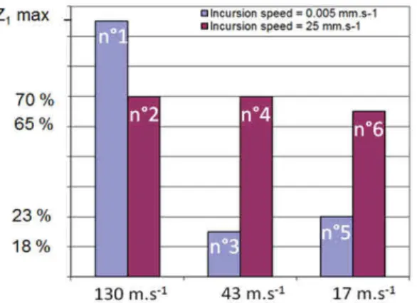
Fig. 9 presents the maximum heights of the deformed coating according to the rotation and the incursion speed. As the heights bars show, the labyrinth tip speed has a significant effect on the heights of deformed coating at low incursion speed (Vinc = 0.005 mm·s-1). In fact, at 43 m·s-1 and 17 m·s-1,
deformed coating is lower whereas rub-grooves depths are identical. This examination indicates the presence of material deformation phenomena at high rotation speed, in contrast to material removal for lower rotation speed. This difference of wear mechanism may be explained by different dissipation level of the contact temperature in the Al-Si 6% coating. This difference is affected by the rotation speed of the labyrinth seal, which impacts the ductile behavior of the coating. It is therefore interesting to observe the interaction forces during the contact.
Figure 9: Maximum heights of deformed coating according to rotational and incursion speed.
3-2 Analysis of interaction forces
The use of interaction force norm provides a global vision of the changing forces during tests. Firstly, two different sets of signals are observed and are associated to different incursion speed (25 mm·s-1 and 0.005 mm·s-1). Fig. 10 shows a typical signal recorded at low incursion speed. It reveals cyclic variations characterized by non-contact periods where forces are close to zero. This phenomenon may probably be associated to a sudden Al-Si 6% pick-up and non-contact time because mechanical clearance adjustment. The increase in maximum forces at each cycle can be in part explained by the increasing of the contact surfaces. Fig. 11 shows a typical signal recorded at high incursion speed. It is composed of a very fast rise time (≈ 0.005 ms), of a maximum which corresponds to the halt of the labyrinth seal incursion and of a fall of forces.
Figure 10: Typical forces signal at low incursion speed (Vinc = 0.005 mm·s-1, Vr = 12 500 rpm).
Figure 11: Typical forces signal at high incursion speed (Vinc = 25 mm·s-1, Vr = 37 500 rpm).
Secondly, the norm is used as a quantitative approach and allows the establishment of a maximum force value induced by the contact. Fig. 12 presents maximal forces recorded versus rotation and incursion speed. Maximum forces generated by tests at high incursion speed are significantly higher than those at low incursion speed. At low incursion speed, maximum forces are included in a range from 1 % to 9 % of the maximum forces compared to a range from 38 % to 100 % of the maximum forces for high incursion speed. Moreover, rub-grooves characterized by a low amount of deformed coating are obtained with forces lower to 9 % of the maximum forces.
Another trend is observed by comparing the maximum forces evolution for different incursion speeds. At low incursion speed, the increase of rotation speed induces a gradual increasing of the maximum interaction forces. Conversely for high incursion speed, when the rotation speed decreases, interaction forces increases.
Figure 12: Maximum interaction forces versus rotation speed (Vr) and incursion speed (Vinc).
3-3 Micrographic rub-grooves observations
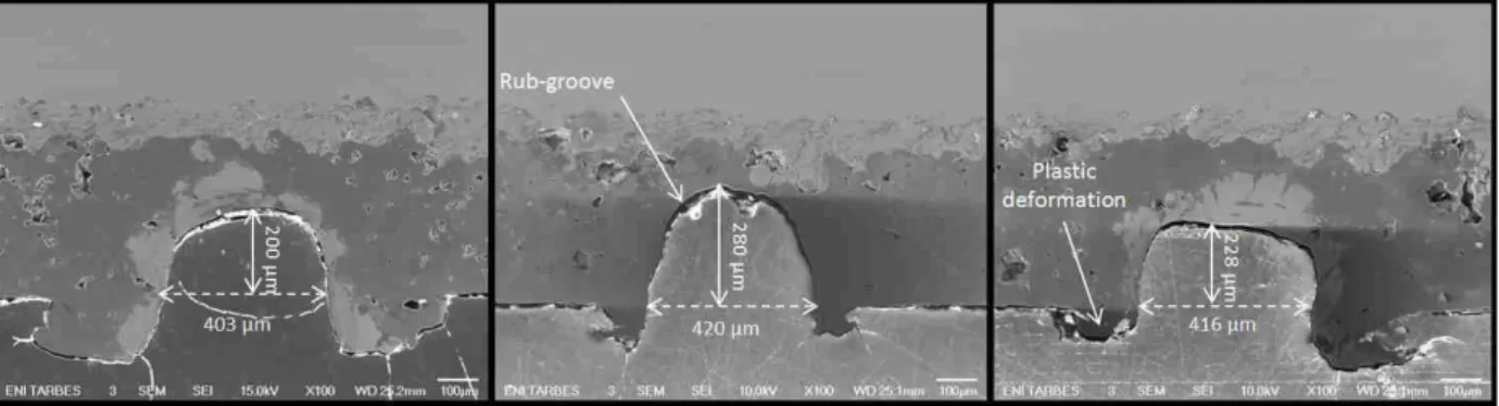
Micrographic rub-grooves observations were performed on the Al-Si 6% abradable surface from test n°1. Fig. 13 shows a section view of three rub-grooves from test n°1 (Vinc =
0.005 mm·s-1, Vr = 37 500 rpm, Dp = 0.2 mm). This view is
the place where the incursion depth of the labyrinth teeth is the greatest. Rub-grooves formed in Al-Si 6% are slightly wider than the initial tooth dimension. Considering the coiled shape of coating deformed outside the rub-groove, the SEM image demonstrates the existence of a material expulsion mechanism by plastic deformation on the both side of the rub-groove (fig.13). Moreover, a slight Al-Si 6% densification is identified around the rub-groove.
Nevertheless, EDX analysis of the rub-grooves on the Al-Si 6% coating identified the presence of nickel and chrome, which are basic elements of 718 alloy, coming from the labyrinth seal teeth (Fig. 14a). This mater transfer from the labyrinth seal to the abradable coating is made of an accumulation of layers in the rub-groove (Fig. 14b).
(a) (b)
Figure 14: (a) SEM image in backscattered electron mode of the first rub-groove from test n°1, (b) SEM image of accumulated
layers of 718 alloy.
4- Conclusion
To optimize turbo-engines performances by reducing the mechanical clearance between rotary parts, contact between labyrinth seals and abradable coatings must be understood. This requirement needs to study and characterize a material couple (where one material undergoes while the other imposes) by simulating interactions in operating conditions. Interactions between an Al-Si 6% abradable coating and a 718 alloy labyrinth seal were performed using a high speed test rig specially developed to achieve a maximum interaction speed of 130 m·s-1.
A first assessment of high speed interactions has been carried out by an analysis of test samples. Visual rub-grooves observations, accurate profile measurements, maximum interaction forces analysis and micrographic examinations reveal different material deformation and wear phenomena and significant interaction parameters:
· Observation of damages by a phenomenon of deformation on the Al-Si 6% coating at high incursion speed and high rotation speed.
· Observation of a material removal wear phenomenon at low incursion speed and low rotation speed considering transfer on Al-Si 6% coating from labyrinth seal teeth, characterized by an accumulation of layers in the rub-groove.
· Influence of the labyrinth rotation speed on the rub-groove morphology and on interaction forces.
However, it is necessary to complement this study by evaluating the abradable behavior about radial incursion. A test campaign should be achieved by fixing test parameters to perform successive incursions.
5- Acknowledgment
These investigations were supported by the European Commission within the FP7 E-BREAK project under Grant agreement no: 314366 and by SAFRAN-TURBOMECA, and received the financial support of the Agence Nationale de la Recherche et de la Technologie (ANRT) which are both gratefully acknowledged.
7- References
[CT1] D. Collins, J. Teixeira, and P. Crudgington. The
degradation of abradable honeycomb labyrinth seal performance due to wear. Sealing Technology, pages 7 – 10, 2008.
[C1] M. Cuny. Contribution to the local characterization of
pairs of materials involved during rotor / stator contact in a turbomachine. PhD thesis, Université de Lorraine, 2012.
[DP1] I.R. Delgado and M.P. Proctor. Continued
investigation of leakage and power loss test results for competing turbine engine seals. Technical report, NASA/TM-2006-214420, 2006.
[DE1] M. Dorfman, U. Erning, and J. Mallon. Gas turbines
use abradable coatings for clearance-control seals. Sealing Technology, 97(1):7- 8, 2002.
[DR1] P. Dowson, S.L. Ross, and C. Schuster. The
investigation of suitability of abradable seal materials for application in centrifugal compressors and steam turbines. In Proceedings of the twentieth turbomachinery symposium, 1991.
[DW1] P. Dowson, M.S. Walker, and A.P. Watson.
Development of abradable and rub-tolerant seal materials for application in centrifugal compressors and steam turbines. Sealing Technology, (12):5 – 10, 2004.
[GV1] A.J.M Gamal and J.M. Vance. Labyrinth seal leakage
test: tooth profile, tooth thickness, and eccentricity effects. ASME Journal of Engineering for Gas Turbines and Power, page 130:012510, 2008.
[JT1] G. Jacquet-Richardet, M. Torkhani, P. Cartraud, F. Thouverez, T. Nouri Baranger, M. Herran, C. Gibert, S. Baguet, P. Almeida, and L. Peletan. Rotor to stator contacts in turbomachines. review and application. Mechanical Systems and Signal Processing, 40(2):401 – 420, 2013.
[MB1] Y. Maozhong, H. Baiyun, and H. Jiawen. Erosion
wear behaviour and model of abradable seal coating. Wear, 252:9 – 15, 2002.
[MH1] Z. Mutasim, L. Hsu, and E. Wong. Evaluation of
plasma sprayed abradable coatings. Surface and Coatings Technology, 54-55:39 – 44, 1992.
[R1] R. Rajendran. Gas turbine coatings: An overview.
Engineering Failure Analysis, 26(0):355 – 369, 2012.
[SG1] R.K Schmid, F. Ghasripoor, M. Dorfman, and X. Wie.
An overview of compressor abradable thermal sprays. In Surface Engineering International Thermal Spray Conference ITSC, page 406, 2000.
[WA1] J.K. Whalen, E. Alvarez, and L.P. Palliser. Thermoplastic labyrinth seals for centrifugal compressors. In Proceeding of the thirty third Turbo Symposium, 2004.
[W1] S. Wilson. Ensuring tight seals. Technical report, Sulzer