HAL Id: hal-01952036
https://hal.archives-ouvertes.fr/hal-01952036
Submitted on 11 Dec 2018
HAL is a multi-disciplinary open access
archive for the deposit and dissemination of sci-entific research documents, whether they are pub-lished or not. The documents may come from teaching and research institutions in France or abroad, or from public or private research centers.
L’archive ouverte pluridisciplinaire HAL, est destinée au dépôt et à la diffusion de documents scientifiques de niveau recherche, publiés ou non, émanant des établissements d’enseignement et de recherche français ou étrangers, des laboratoires publics ou privés.
Vincent Mazars, Guillaume Couégnat, Olivier Caty, Sébastien Denneulin,
Gérard Vignoles
To cite this version:
Vincent Mazars, Guillaume Couégnat, Olivier Caty, Sébastien Denneulin, Gérard Vignoles. Multi-scale damage modeling of 3D ceramic matrix composites from in-situ X-ray tensile tests. ECCM18, Jun 2018, Athens, Greece. pp.24 - 28. �hal-01952036�
V. Mazars, G. Couégnat, O. Caty, S. Denneulin and G.L. Vignoles
MULTI-SCALE DAMAGE MODELING OF 3D CERAMIC MATRIX
COMPOSITES FROM IN-SITU X-RAY TENSILE TESTS
Vincent Mazars1,2, Guillaume Couégnat1, Olivier Caty1, Sébastien Denneulin2, Gérard L Vignoles1 1LCTS (Univ. de Bordeaux/ CNRS/ CEA/ SAFRAN CERAMICS),
3 allée de la Boétie, F-33600 Pessac, France
2SAFRAN CERAMICS, F-33185 Le Haillan, France
Keywords: Woven Ceramic Matrix Composites, Tomography, Cracks, Multi-scale finite element
analysis
Abstract
SiC/SiC composites are actively developed to be used in hot parts of civil aircraft engines to improve efficiency and reduce the environmental impact. To understand and to predict the location of damage in such materials is critical. The present paper proposes a multi-scale finite element modeling strategy to simulate the onset of damage at the mesoscopic scale. Virtual tests are carried out at the microscopic scale on representative microstructures to identify the homogenized mechanical properties and continuum damage laws of the yarns. Transverse cracks are then simulated at the mesoscopic scale on 3D meshes generated directly from X-ray synchrotron micro-tomography (µCT) images. Predicted damage events are successfully compared to those obtained experimentally on the same specimen during in-situ tensile tests. Since only physical parameters at the constituent scale are required, such an integrated approach could offer the opportunity to design and optimize numerically the material to delay the initiation of critical damage events.
1. Introduction
Ceramic matrix composites (CMCs) are complex heterogeneous materials displaying excellent thermomechanical properties at high temperatures. They appear as promising candidates for thermostructural applications, especially to replace metallic alloys in hot parts of aircraft engines. They can dramatically improve the efficiency of civil aircraft motors and thus reduce fuel consumption. The service lifetime prediction required for such applications is challenging. To understand and to predict the damage events is crucial to determine the range of applicability of the material. Optimization of CMC structures to delay the apparition of the cracks is currently empirical and results in costly experimental campaigns. In order to reduce the number of experiences and to reveal physical grounds of damage initiation, finite elements (FE) simulations are of great interest. CMCs display a multi-scale structure : microscopic scale is the scale of individual constituents, mesoscopic scale assumes yarns as homogeneous and macroscopic scale considers the whole material as homogeneous. Mesoscopic scale simulations seem to be a good compromise between computation times and a sufficiently accurate description of the material architecture.
Great efforts were made in the past decades to simulate damage in woven composites at the mesoscopic scale with various numerical techniques. Among them, discrete cracks insertions [1,2], continuum damage laws [3-6] or more advanced numerical methods such as A-FEM [7,8] can be used. Whatever the chosen method, input data for mesomechanical analysis are not always straightforward to measure experimentally. Multi-scale strategies are an elegant way to overcome these limitations. Homogenized mesoscopic properties are numerically identified from simulations performed at the micro-scale. Such approach was for instance proposed by [9,10] to identify the ply failure envelopes
V. Mazars, G. Couégnat, O. Caty, S. Denneulin and G.L. Vignoles
for multiaxial loading cases. To predict the behavior of the material in use, numerical models must rely on precise observations of the microstructure as well as on a good understanding of the damage mechanisms. Based on the results of a previous work [11], damage mechanisms in woven SiC/SiC composites were identified through in-situ tensile tests carried out under µCT on small-sized specimen. Transverse yarns cracking was identified as the first intra-yarns damage mechanism. Recently, in-situ tensile tests under SEM were performed [12] on a similar material, revealing intra-yarns transverse damage mechanisms such as transverse fiber/matrix debondings and matrix cracking. We propose here a micro-meso modeling approach to simulate first transverse cracks at the meso-scale. Based on the results of damage virtual tests at the micro-scale, the in-plane properties and continuum damage laws of the yarns are derived. 3D mesoscopic damage calculations are then performed on a specimen scanned by µCT. The location of simulated cracks are then compared with those observed experimentally on the same specimen.
2. Micro-scale damage modeling
2.1. Micro-scale cell generation and constitutive equations
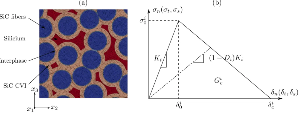
Representative microstructures are generated through Random Sequential Adsorption (RSA) algorithm [13]. We assume that the fibers are circular, parallel, with a constant diameter of 12µm and that the surface fibers fraction reaches 50%. Concentric deposits of interphase and SiC CVI are added around the fibers. The thickness of the deposits are provided by [14]. The size of the elementary volumes (EV) is 50µm, which roughly corresponds to the characteristic length of FE mesh element at the meso-scale. The generated microstructure is then discretized and meshed using the 2D mesher [15]. If 3D calculations are needed (for instance to identify the complete stiffness tensor), the mesh is eventually extruded on a small length and meshed with tetrahedral elements. Fig.1a presents a typical mesh of an EV where the constituents are indicated.
For simulating fiber/matrix debondings, zero-thickness cohesive elements (CZM) are inserted between the interphase and the SiC CVI matrix. A simple bilinear decoupled traction/separation law presented Fig.1b is retained.
Figure 1. (a) Typical EV meshed at the micro-scale and (b) Bilinear traction/separation law used for
CZM and for isotropic bulk elements.
We assume that the fibers remain elastic. For the other constituents, a continuum damage law was chosen. The crack-band theory [16] is commonly used to regularize continuum damage laws with regard to a characteristic length and thus reducing the mesh-dependency. Such approach requires the
V. Mazars, G. Couégnat, O. Caty, S. Denneulin and G.L. Vignoles
introduction of a new material parameter which is the fracture surface energy Gc. A damage initiation
criterion based on the maximum principal tensile stress is retained. A traction/separation law similar to that shown on the Fig.1.b can be derived, where the equivalent displacement is defined as the product of the equivalent strain with the characteristic length of the mesh element. As the size of the mesh elements is of the same order of the crack opening, a uniform stiffness tensor degradation is assumed. The damage laws were implemented in Abaqus UMAT in 2D and 3D. The values of elastic properties and damage parameters used for the micro-scale damage simulations are summarized in Table 1.
Table 1. Constituents properties at the micro-scale (from [14,17,18]).
E (GPa) n s0 (MPa) Gc (J.m-2) K (MPa.mm-1)
Fibers 420 0.17 - - -
Interphase 21 0.22 185 5 -
CZM - - 155 5 7.5.108
SiC CVI 439 0.17 600 6 -
Silicium 165 0.22 425 5.5 -
2.2. Virtual tests at the micro scale
Fig.2 presents the results of damage simulations on an EV for transverse tension (Fig2.a) and plane shear (Fig.2.b). The stress-strain curves are characteristic of a quasi-fragile behavior with a first linear domain and then a progressive degradation of the mechanical properties until a sudden loss of stiffness. Damage variables (Dn for cohesive interfaces and D for bulk elements) are also presented for
both mechanical virtual tests at the peak stress and after the drop in load. First damage events are located at the fiber/matrix interfaces. Then these debondings percolate until a through-thickness crack is formed which corresponds to experimental evidences. The crack develops in a direction normal to the stress axis (90° for tensile test and 45° for plane shear). The strength is of the order of 200 MPa and the dissipated energy (calculated as the area under the curves) is around 10 J.m-2. These values are
reasonable in comparison with commonly used values in literature for mesoscopic calculations on these materials [19].
Figure 2. Example of virtual tests carried out at micro-scale : (a) transverse tension and (b) plane
V. Mazars, G. Couégnat, O. Caty, S. Denneulin and G.L. Vignoles
3. Micro-meso bridge
3.1. Identification of the damage laws for the yarns
Implementation of the yarn damage law requires the identification of (i) a damage initiation criterion, (ii) the effect of damage on the stiffness tensor and (iii) the evolution of damage variables driving cracks propagation. Damage initiation criterion is determined by plotting the fracture stress envelopes in the plane normal to the fibers (only the transverse failure is considered here). Damage virtual tests are performed on about ten EV with proportional tensile-shear and biaxial loadings. Fig.3.a shows the mechanical responses obtained in the s22-s23 plane with different e23/e22 ratios. Each color
corresponds to a single EV. The same procedure is carried out for biaxial tests and the results are plotted in the s22-s33 plane with different e33/e22 ratios (Fig.3.b). The peak stresses can be described
adequately by ellipses. We therefore propose a quadratic damage initiation criterion where the values of critical stress in each direction is derived from the parameters of the fitting ellipses.
Figure 3. Damage criterion identification of multiple micro cells : (a) tensile/shear and (b) biaxial
loading responses.
These calculations performed at the micro scale highlight the formation of a main through-thickness crack (see Fig.4.a) oriented by the load axis. We can thus define at the mesoscopic scale a new basis where xII corresponds to the axis of principal strain. As only the transverse cracking of the yarns is
considered, the direction xI is assumed to be identical to that of x1 (see Fig.4.b).
To evaluate the effect of damage on the stiffness tensor at the meso-scale, homogenization calculations are performed at different deformation states for uniaxial tensile stress in the x2 direction. Fig.4.c
shows the evolution of the 9 terms of the stiffness tensor of the EV. The terms involving the stress axis (C12, C22, C23 and the shear terms C44 and C66) are dramatically reduced with transverse crack
apparition while the other terms remain almost constant. We assume here that the x2 axis is very close
to the principal axis xII. We can therefore consider that the degradation of the stiffness tensor presented
is expressed in the basis of principal strain. Note that the terms modified by the crack development are the same than those assumed in the phenomenological meso-scale damage model by [20] (and reused later in [3,4,6]) in the case of a solicitation in T mode where only the variable of damage DT is
V. Mazars, G. Couégnat, O. Caty, S. Denneulin and G.L. Vignoles
Figure 4. (a) Main cracks developed for traction and shear stress showing the basis of the crack, (b)
scheme of a mesoscopic scale element where the initial basis is superposed to the principal strain basis and (c) stiffness tensor terms evolutions for increasing strain levels.
For the sake of simplicity, it is considered that all the terms not involved in the direction of solicitation remain constant and that the other terms decrease linearly with increasing damage. We also assume that Gc is constant regardless of the direction of loading. Once the damage criterion is fulfilled within
an element, the crack direction remains the same and the stiffness tensor keeps degrading in the xII
direction. The meso-scale damage law was implemented in an Abaqus UMAT.
3.2. Validation of the micro-meso bridge
We propose here a validation case of the micro-meso homogenization procedure. A large cell (of the average size of an entire yarn) is divided into 36 EV of 50µm each. Pure tensile and shear damage calculations are performed on each of the 36 cells to identify the peak stresses values and the energy rates as described previously. Complete 3D elastic stiffness tensor identification is also performed, using mixed boundary conditions [21]. These quantities are introduced as parameters for the damage law of each corresponding meso element.
Fig.5 compares the results of the simulation carried out directly on the large cell with those obtained on the corresponding meso cell for tensile loading in x2 axis. The mappings of the damage variables
highlight the formation of a main crack at both cases. The initial stiffness and the value of the peak stress is also very similar (around 200 MPa for about 0.1% strain). There are slight differences in the softening part of the curve, the direct calculation being more brittle. However, it can be concluded that the proposed micro-meso bridge is acceptable and allows the transverse damage mechanisms of the yarns to be sufficiently well described at the meso-scale. The prescribed size of meso-element appears to be a good compromise to properly reproduce the stress load transfers.
V. Mazars, G. Couégnat, O. Caty, S. Denneulin and G.L. Vignoles
Figure 5. Comparison of the results obtained for direct simulation performed at micro-scale and the
corresponding results at the meso-scale with the damage homogenization procedure.
4. Simulation of damage development at the macro-scale
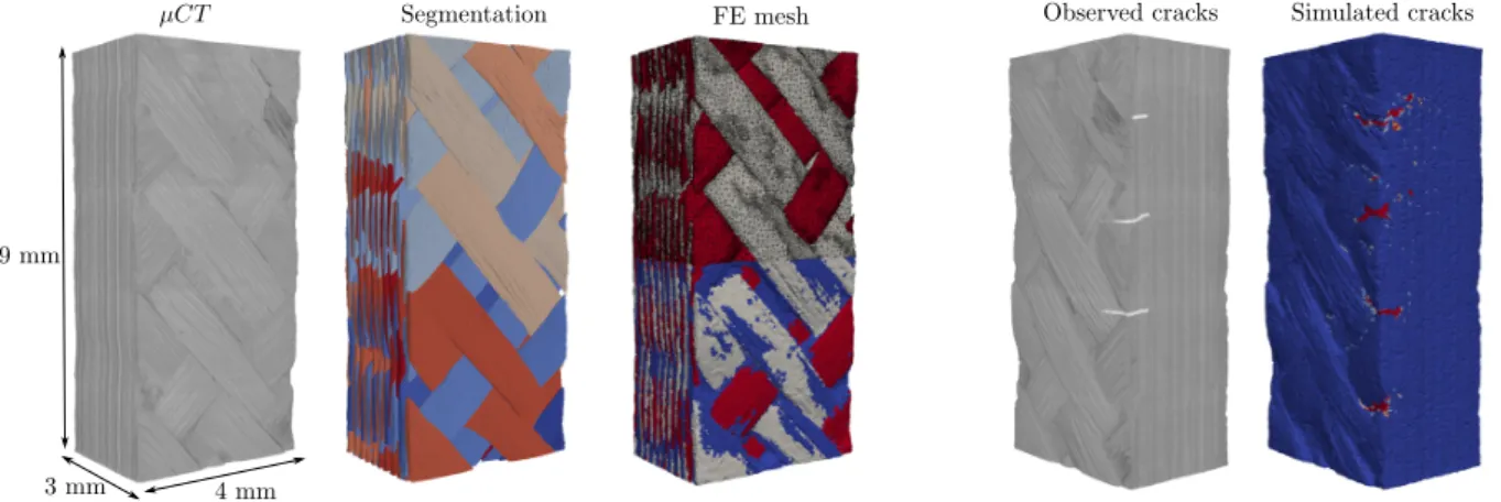
In-situ tensile tests were performed under X-ray synchrotron radiation at Soleil on the PSICHE beamline at a resolution of 2.6µm on small sized specimens (4x3x10 mm). A high-fidelity finite elements model was constructed from the µCT images (see [11] for details on the segmentation procedure). Since the commonly used voxels meshes seem inadequate to correctly predict the onset of damage [22], a conformal tetrahedral mesh was generated [23]. Fig.6 (left) illustrates the procedure, from µCT images to 3D mesoscopic FE model. The final mesh contains approximatively 2 million of elements. The accurate description of the material geometry allows to compare directly the simulated damage with the one observed experimentally on the same specimen.
To reproduce the experiment, the boundary conditions prescribed at the top and the bottom of the scanned specimen are deduced from Digital Volume Correlation calculations. Damage simulations are carried out herein using the meso-scale damage law identified from micro-scale virtual testing. Fig.6 compares the location of the first cracks observed experimentally to the ones predicted by FE simulations. The results are in good agreement since all the cracks are predicted by FE simulations at the exact location. Note that one crack predicted by the FE analysis was not observed. These results are still very encouraging on the ability of our approach to predict the first cracks formation.
Figure 6. (left) Image-based FE meso-models construction from µCT images to FE models and (right)
V. Mazars, G. Couégnat, O. Caty, S. Denneulin and G.L. Vignoles
5. Conclusions
A micro-meso modeling strategy was proposed to simulate the damage events at the meso-scale. First, damage models were constructed at the micro scale for in-plane mechanical solicitations. Virtual tests were conducted on stochastic representative micro-cells to derive continuum damage laws at the upper scale. The micro-meso homogenization was validated on an entire yarn. Finally, simulations were conducted on 3D FE meshes obtained from µCT images acquired during in-situ tensile tests. The proposed damage laws derived from the multi-scale procedure were sufficient to predict the location of the first damage events at the meso-scale and the correct load for which they appear. These results are encouraging since only measurable physical parameters at the constituent scale are required. The proposed integrated approach could in the future be used as a virtual design tool to optimize the structure of the material with regard to damage mechanisms.
Acknowledgments
The authors are grateful to the PSICHE Soleil beamline team, and in particular to Andrew King for image acquisition.
References
[1] A. Doitrand, C. Fagiano, N. Carrere, V. Chiaruttini and M. Hirsekorn. Damage onset modeling in woven composites based on a coupled stress and energy. Engineering Fracture Mechanics, 169:189–200, 2017.
[2] G. Couégnat. Approche multiéchelle du comportement mécanique des composites à matrice céramique. PhD thesis. Université Sciences et Technologies Bordeaux, 2008.
[3] M. Zako, U. Yasutomo and K. Tetsusei. Finite element analysis of damaged woven fabric composite materials. Composites Science and Technology, 63:507–516, 2003.
[4] A.R. Melro, P.P. Camanho, FM. Andrade Pires and S.T. Pinho. Numerical simulation of the non-linear deformation of 5-harness satin weaves. Computational Materials Science, 61:116–126, 2012.
[5] E. Riva, G. Nicoletto. Modeling and prediction of the mechanical properties of woven laminates by the finite element method. WIT Transactions on State-of-the-art in Science and Engineering, 21, 2005.
[6] S.V. Lomov, D.S. Ivanov, I. Verpoest, M. Zako, T. Kurashiki, H. Nakai, S. Hirosawa. Meso-FE modelling of textile composites: Road map, data flow and algorithms. Composites Science and Technology, 67:1870–1891, 2007.
[7] Q. Yang and M. Naderi. A new augmented finite element method (A-FEM) for progressive failure analysis of advanced composite materials. Numerical Modelling of Failure in Advanced Composite Materials, 265–308, 2015.
[8] B.N. Cox, H.A. Bale, M. Begley, M. Blacklock, B. Do, T. Fast, M. Naderi, M. Novak, V.R. Rajan, R.G. Rinaldi, R.O. Ritchie, M.N. Rossol, J.H. Shaw, O. Sudre, Q. Yang, F.W. Zok and D. Marshall. Stochastic virtual tests for high-temperature ceramic matrix composites. Annual Review of Materials Research, 44:479–529, 2014.
V. Mazars, G. Couégnat, O. Caty, S. Denneulin and G.L. Vignoles
[9] PP. Camanho, A. Arteiro, A.R. Melro, G. Catalanotti and M. Vogler. Three-dimensional invariant-based failure criteria for fibre-reinforced composites. International Journal of Solids and Structures, 55:92–107, 2015.
[10] F. Naya, C. Gonzáles, C.S. Lopes, S. Van der Veen and F. Pons. Computational micromechanics of the transverse and shear behavior of unidirectional fiber reinforced polymers including environmental effects. Composites Part A: Applied Science and Manufacturing, 92:146–157, 2017.
[11] V. Mazars, O. Caty, G. Couégnat, A. Bouterf, S. Roux, S. Denneulin, J. Pailhes and G.L. Vignoles. Damage investigation and modeling of 3D woven ceramic matrix composites from X-ray tomography in-situ tensile tests. Acta Materialia, 140:130–139, 2017.
[12] K.M. Sevener, J.M. Tracy, Z. Chen and J.D. Kiser. Crack opening behavior in ceramic matrix composites. Journal of the American Ceramic Society, 1–14, 2017.
[13] B. Widom. Random sequential addition of hard spheres to a volume. The Journal of Chemical Physics, 44:3888–3894, 1966.
[14] Y. Gowayed , G. Ojard, R. Miller, U. Santhosh, J. Ahmad and R. John. Correlation of elastic properties of melt infiltrated SiC/SiC composites to in situ properties of constituent phases. Composites Science and Technology, 70:435–441, 2010.
[15] H. Borouchaki and P. Laug. Le mailleur adaptatif bidimensionnel BL2D: manuel d'utilisation et documentation. INRIA, 1995.
[16] Z.P. Bažant and B.H. Oh. Crack band theory for fracture of concrete. Matériaux et construction, 16:155–177, 1983.
[17] A. Kaflou. Étude du comportement des interfaces et des interphases dans les composites à fibres et à matrices céramiques. PhD thesis. INSA de Lyon, 2006.
[18] A. Coradi. Modélisation du comportement mécanique des composites à matrice céramique : développement du réseau de fissures. PhD thesis. Université de Bordeaux, 2014.
[19] J. Li, E. Martin, D. Leguillon and C. Dupin. A finite fracture model for the analysis of multi-cracking in woven ceramic matrix composites. Composites Part B: Engineering, 139:75–83, 2018.
[20] S. Murakami. Mechanical modeling of material damage. ASME, Transactions, Journal of Applied Mechanics, 55:280–286, 1988.
[21] D.H. Pahr and H.J. Böhm. Assessment of mixed uniform boundary conditions for predicting the mechanical behavior of elastic and inelastic discontinuously reinforced composites. Comput. Model. Engng. Sci, 34:117–136, 2008.
[22] A. Doitrand, C. Fagiano, F.X. Irisarri and M. Hirsekorn. Comparison between voxel and consistent meso-scale models of woven composites. Composites Part A: Applied Science and Manufacturing, 73:143–154, 2015.
[23] P. Alliez, C. Jamin, L. Rineau, S. Tayeb, J. Tournois and M. Yvinec. 3D Mesh Generation : CGAL User and Reference Manual, 2018.