HAL Id: hal-01167515
https://hal.inria.fr/hal-01167515
Submitted on 24 Jun 2015
HAL is a multi-disciplinary open access
archive for the deposit and dissemination of
sci-entific research documents, whether they are
pub-lished or not. The documents may come from
L’archive ouverte pluridisciplinaire HAL, est
destinée au dépôt et à la diffusion de documents
scientifiques de niveau recherche, publiés ou non,
émanant des établissements d’enseignement et de
Electroencephalography (EEG)-based Brain-Computer
Interfaces
Fabien Lotte, Laurent Bougrain, Maureen Clerc
To cite this version:
Fabien Lotte, Laurent Bougrain, Maureen Clerc.
Electroencephalography (EEG)-based
Brain-Computer Interfaces. Wiley Encyclopedia of Electrical and Electronics Engineering, Wiley, pp.44,
2015, �10.1002/047134608X.W8278�. �hal-01167515�
Electroencephalography (EEG)-based
Brain-Computer Interfaces
Fabien LOTTE
1, Laurent BOUGRAIN
2, Maureen CLERC
31
Inria Bordeaux Sud-Ouest, FRANCE
2
Lorraine University/Inria Nancy Grand-Est, FRANCE
3Inria Sophia Antipolis M´
editerran´
ee, FRANCE
June 1, 2015
Abstract
Brain-Computer Interfaces (BCI) are systems that can translate the brain activity patterns of a user into messages or commands for an interac-tive application. The brain activity which is processed by the BCI systems is usually measured using Electroencephalography (EEG). In this article, we aim at providing an accessible and up-to-date overview of EEG-based BCI, with a main focus on its engineering aspects. We notably intro-duce some basic neuroscience background, and explain how to design an EEG-based BCI, in particular reviewing which signal processing, machine learning, software and hardware tools to use. We present Brain Computer Interface applications, highlight some limitations of current systems and suggest some perspectives for the field.
1
Introduction
Since the first experiments of Electroencephalography (EEG) on humans by Hans Berger in 1929 [1], the idea that brain activity could be used as a commu-nication channel rapidly emerged. EEG is a technique which measures, on the scalp and in real-time, small electrical currents that reflect brain activity. As such, EEG discovery has enabled researchers to measure brain activity in hu-mans and to start trying to decode this activity. After some attempts by music composers to use brain activity to produce music in real time [2, 3], the concept of a Brain-Computer Interface (BCI) was formalised in 1973 by Vidal [4]. A BCI is a system that translates the brain activity patterns of a user into messages or commands for an interactive application, this activity being measured and processed by the system [5, 6]. For instance, a BCI could enable a user to move a cursor on a screen left or right by imagining left or right hand movements, respectively. Since the design of the first real-time BCI in the 90’s [7, 8, 9, 10], the BCI field has grown tremendously, involving hundreds of laboratories and companies around the world, and becoming a more mature field of research and
technology [11, 6]. BCI have indeed evolved to become more robust, more ac-cessible and promising for a wide range of applications including communication and control for motor impaired users [9, 12], gaming targeted toward the general public [13, 14], real-time mental state monitoring [15] or stroke rehabilitation [16, 17].
Designing a BCI is a complex and difficult task which requires multidis-ciplinary knowledge in computer science, engineering, signal processing, neuro-science and psychology. In order to use a BCI, two phases are generally required: 1) an offline training phase during which the system is calibrated and 2) the operational online phase in which the system recognises brain activity patterns and translates them into commands for a computer. An online BCI system is a closed-loop, generally composed of six main steps: brain activity measurement, preprocessing, feature extraction, classification, translation into a command and feedback:
1. Brain activity measurement allows to acquire the raw signals reflecting the user’s brain activity [18]. Various types of sensors can be employed, but in this article we focus on EEG as the measurement technique. 2. Preprocessing consists in cleaning and denoising input data in order to
enhance the relevant information contained in the raw signals [19]. 3. Feature extraction aims to describe the signals by a few relevant values
called “features” [19]. These features can be, for instance, the power of the EEG over selected channels, and in specific frequency bands.
4. Classification assigns a class to a set of features extracted from the signals within a certain time range [20]. This class corresponds to the kind of brain activity pattern identified (e.g., imagined left hand movement or imagined right hand movement). Classification algorithms are known as “classifiers”.
5. Translation into a command associates a command to the brain ac-tivity pattern identified in the user’s brain signals, e.g., a recognised left hand movement could be translated into the command “move the cursor left”. This command is then used to control a given application such as a speller (text editor, see part 4.1) or a robot [21].
6. Feedback is provided to the user to inform him/her about the recognised brain activity pattern. This aims to help the user modulate his/her brain activity and as such improve his/her control over the BCI [5]. Indeed, BCI is a skill that needs to be learned and refined [22].
This whole architecture is summarised in Figure 1. These steps define an online BCI. The BCI research community is in quest of solutions to avoid a time-consuming calibration stage before operating a BCI (see, e.g., [23, 24]). Currently, calibration is generally necessary in order to obtain a reliable BCI operation, and is generally done offline. In this stage, the classification algorithm
is calibrated and the optimal features, and relevant sensors are selected. For this calibration, a training data set needs to be prerecorded from the user. Indeed, EEG signals are highly user-specific, and as such, most current BCI systems are calibrated specifically for each user. This training data set should contain EEG signals recorded while the user performed each mental task of interest several times, according to given instructions. The recorded EEG signals will be used as mental state examples in order to find the best calibration parameters for this user.
Figure 1: General architecture of an online brain-computer interface, with ex-amples of applications.
It should be noted that, although BCI are a very promising technology, they still suffer from a number of limitations that need to be overcome before they can be used in practical applications, outside laboratories. Among these, we can mention the relatively modest robustness and reliability of such sys-tems. Indeed, most BCI very rarely yield 100% correct recognition of the user’s mental commands [25, 26, 27], and some users are completely unable to use a given type of BCI [28]. Moreover, while current EEG-based BCI are reasonably stable in laboratory conditions, their performance decreases significantly when confronted to real-word, complex environments, over long periods, or when the user is moving [29, 30, 31]. BCI reliability is also much lower when used by severely motor-impaired users such as locked-in patients [32]. EEG-based BCI also generally require relatively long calibration time [24] and may also require long to very long human training time [22, 33]. A number of challenges there-fore still need to be tackled by the research community to yield robust, practical
EEG-based BCI.
In this article, we aim at providing an accessible and up-to-date overview of EEG-based BCI (EEG being by far the most used modality for BCI design), with a main focus on its engineering aspects. After a brief presentation of some basic BCI-related neuroscience background (Section 2), Section 3 describes how to design an EEG-based BCI, and notably how to process and classify EEG signals. Then, Section 4 presents the main current applications of BCI technologies, while Section 5 details the main hardware and software components available to design these BCI. Finally, Section 6 concludes the article with a discussion on the future of BCI research and technology.
2
Some brief neuroscience background
At the centre of the BCI loop is the user and his/her brain, whose activity is being measured and processed by the BCI. In this section, we provide some brief notion of brain anatomy relevant for BCI and briefly describe how to measure brain activity and what kind of brain activity patterns can be detected and used by the BCI.
2.1
Anatomy and brain imaging
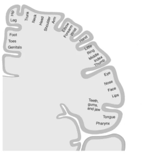
The brain includes three main parts: the cerebellum, the brainstem and the cerebrum (which includes the cortex). The cortex is composed of the right and left cerebral hemispheres, each of which being subdivided into four lobes: frontal, parietal, temporal and occipital. The central fissure (or central sulcus) separates the parietal lobe from the frontal lobe, and the primary motor cortex from the primary somatosensory cortex. The frontal lobe is associated with motor learning, problem solving, language, reasoning, planning, memory, and is the core for personality and emotions. The primary motor cortex, located in this lobe, is associated with motor activity, for planning and executing move-ments. Broadly speaking, the muscles to the left of the body are controlled by the right hemisphere, and the left hemisphere controls the right side. The pri-mary motor cortex sends information needed to perform voluntary movements and receive sensory information from other brain areas. The received sensory information is used as feedback to plan and execute movements. Furthermore, the primary motor cortex contains a broad representation of the anatomy, see Figure 2, where different body parts are partially controlled by overlapping re-gions of the motor cortex.
The parietal lobe plays an important role in the perception of tactile stim-uli: it responds to sensory inputs, such as temperature, pressure and pain. It is also associated with movement coordination and language. The occipital lobe is responsible for the early stages of processing of visual stimuli and spatial recog-nition. The temporal lobe plays an important role in the perception of auditory and olfactory stimuli. It is also associated with coordination and balance,
emo-tions, memory and face recognition.
Figure 2: Primary motor cortex of the right hemisphere: point-by-point cor-respondence of a body area with a specific area of the primary motor cortex. The central rectangle of Figure 3 indicates the corresponding locations on EEG electrodes.
There are several systems for recording brain activity. They can be classi-fied i) by the location at which the signal is measured (invasive vs non-invasive) and ii) by the type of sensors used to record the brain signals. These sen-sors can measure electric, magnetic or chemical signals. BCI based on invasive recordings such as electrocorticography and intracortical electrodes are mainly performed with animals and human patients implanted for clinical diagnosis. Non-invasive technologies, which do not penetrate the skin, do not represent any risk for the user, such as, haemorrhages, infections or bioincompatibility. Some of the available non-invasive techniques include functional magnetic reso-nance imaging (fMRI) and functional near infrared spectroscopy (fNIRS) - sen-sitive to blood oxygenation - positron emission tomography (PET) and single photon emission computed tomography (SPECT) - based on nuclear medicine - , transcranial Doppler ultrasound (TcD) - based on ultrasound - and finally magnetoencephalography (MEG) and electroencephalography (EEG) - directly measuring electromagnetic fields generated by neuronal electrical activity.
EEG is the most common method for recording brain signals in humans because it is safe, affordable, easy to use, and because it has a high temporal resolution (of the order of milliseconds) [34]. EEG electrodes, placed on the scalp, can be either “passive” or “active”. Passive electrodes, which are metal-lic, are connected to an amplifier by a cable. Active electrodes have an inbuilt preamplifier to make them less sensitive to environmental noise and cable move-ments. Both types of electrodes need gel or saline liquid to operate, in order
to reduce the skin-electrode contact impedance. This prevents their use for long periods, such as a whole day, because the gel dries with time, causing the impedances to rise and the signals to degrade. For this reason, dry electrodes are currently being developed and tested for BCI (see Section 5). Despite a low spatial resolution (at best the inter-distance between electrodes is 1-2 cm) and a low signal-to-noise ratio, this solution presents many advantages for widespread use.
In early recordings of brain activity using EEG, there was no rule concerning the layout of the electrodes on the head. Then common protocols were defined to standardise the layout, the first one being the 10-20 system [35], still used today. The name of the system comes from the inter-electrode distances, which are approximately 10% or 20% of the front-to-back or right-to-left head perimeters (see Figure 3).
An amplifier is necessary for acquiring measurable signals. Modern ampli-fiers produce a set of digital signals, one per channel. Each channel measures the electric potential difference between the electrode to which it is connected and a reference electrode. This reference electrode can be placed anywhere on the head, but should not be at a location where the activity is very strong, because it could prevent weaker activity of other regions from being correctly measured. Many positions can be selected as reference, for instance an earlobe, or the mastoid region behind the ear. Some amplifiers apply a common aver-age reference, by subtracting from each channel the averaver-age potential over all channels, a good strategy when recording from a large number of electrodes (so called high-density EEG). A ground electrode is also necessary to prevent power line interference with the low-amplitude signals of interest. This ground can be placed anywhere on the body, and it is sometimes also placed on the scalp. The next sections describe the three main brain activity patterns that are used to design EEG-based BCI: Event Related Desynchronization/Synchronization, Event Related Potentials and Steady State Evoked Potentials. Note that these are not the only existing brain activity patterns used in EEG-based BCI, but only the most popular and so far the most efficient for communication and control applications.
2.2
Event Related Desynchronization/Synchronization
Event-Related Desynchronization or Synchronization (ERD/ERS), corresponds to amplitude variations of EEG signals oscillations, i.e., amplitude changes in the power of EEG signals in certain frequency bands [36]. ERD corresponds to thousands or millions of cortical neurons firing in a more desynchronised way than in the baseline (rest condition where no event is occurring). This results in a smaller amplitude oscillations in scalp EEG signals. On the contrary, ERS corresponds to cortical neurons firing synchronously, hence leading to a resulting large amplitude of scalp EEG signals. More formally, according to Pfurstcheller et al, ERD and ERS can “be considered to be due to a decrease or an increase in synchrony of the underlying neuronal populations” respectively [36]. ERD
Figure 3: Extended 10-20 EEG system. Electrodes are identified with labels: the letters correspond to cortical locations: frontal (F), temporal (T), parietal (P), occipital (O), central (C) and combinations of these to indicate intermediate locations (Fp means frontal polar and corresponds to the anterior pre-frontal lobe). The electrode numbers indicate laterality: odd numbers to the left, even numbers to the right, and the letter “z” (meaning zero) on the midline. The electrode layout displayed considers 10% intermediate distances. The central rectangle indicates the location of the primary motor cortex (adapted with the permission of gtec medical engineering GmbH).
and ERS have been suggested to reflect cortical activation and deactivation, respectively [36].
ERD/ERS can be observed during a number of different mental tasks, and can thus be used as a feature to drive a BCI. In particular, ERD/ERS can be observed during Motor Imagery (MI), as well as executed movement [37] (see, e.g., Figure 7). For instance, an execution or an imagination of a left-hand movement leads to an ERD in the µ (8-12Hz) and β (16-24Hz) bands (the so-called sensorimotor rhythms) during movement, and to an ERS in the β band after movement. Both the ERD and the ERS occur in the controlateral senso-rimotor cortex (in the hemisphere opposite to the hand used). ERD/ERS can also be observed during diverse mental imagery tasks, such as mental rotation of geometric figures or mental subtractions, among others [38, 39].
ERD/ERS-based BCI have three main advantages: 1) they can be rather natural and intuitive to use, since their users “just” have to imagine a specific task to send control commands, 2) they do not require any stimulus (contrary to ERP-based BCI, see Section 2.3), which enables the users to devote all their
sensory attention to the feedback of the BCI and/or to their external environ-ment 3) they can be used in a self-paced way, that is, the user can initiate the task (and hence the command) at will. Their main drawback is the fact that such BCI require substantial training on the user side, to find the correct imag-ination strategy that leads to the clearest and most distinct ERD/ERS. Also, this kind of BCI can currently only be used with a maximum of 3 or 4 different mental imagery tasks to ensure maximal performances: with more tasks, their recognition accuracy becomes considerably degraded, and therefore the overall BCI efficiency decreased [40].
2.3
Event Related Potentials
Event Related Potentials (ERPs) are stereotyped deflections of the EEG, related to a sensory, cognitive or motor event. The “Event” of an ERP must come at a precise measurable time, called the time trigger of the event. Typically, if a person is receiving a sensory stimulus, ths time trigger is the instant at which the stimulus is presented, or, in case of a button press, it is the instant at which the muscular activity exceeds a certain threshold. The deflections measured by the ERPs are represented as waveforms, and sometimes called waves. But in spite of this terminology, ERPs do not display sustained oscillations, contrarily to the ERD/ERS of part 2.2.
ERP nomenclatures are very varied: they can indicate their context of oc-currence (Somatosensory Evoked potential (SEP) - in response to a tactile stim-ulation; Error Potential (ErrP) - related to an error), or the polarity of the deflection: negativity indicating a decrease in amplitude, and positivity an in-crease in amplitude. For instance, the Mismatch Negativity (MMN) - is a nega-tive deflection of the EEG in response to a deviant stimulus within a sequence of repeating stimuli, either auditory or visual [41]. The timing of the deflection is indicative of the level of processing involved: very early components (20 to 100 ms after the event trigger) are automatic, reflex responses whereas later deflections occurring after 200 ms, reflect a higher-level, cognitive, processing. This timing is also often part of ERP nomenclatures: an auditory N100 or visual N1 are early negative deflections that may be modulated by attention; the P300 wave - positive deflection, occurring approximately 300 ms after the presentation of a deviant stimulus to which the person is paying attention.
Figure 4: An auditory oddball sequence: the deviant sounds (high-pitched, in green) are presented in a stream of standards (low-pitched, in red). A P300 wave occurs after the deviant sounds. When a person is asked to actively attend to the deviants, e.g. by counting their occurrences, the P300 wave is stronger than if the auditory stream is only passively attended to.
Although not reflected in their nomenclature, spatial locations of ERPs are sterotypical. For instance, the P300 wave is similar to the Mismatch Negativity because both are produced by an “oddball” effect (see Figure 4), and they both occur at similar latencies. The (negative) MMN would be canceled out by the (positive) P300 (which has higher amplitude) if they were not located at dif-ferent regions on the scalp: the P300 location is parieto-occipital, whereas the MMN occurs on occipital (visual stimuli) or fronto-central (auditory stimuli) electrodes. We next present in more detail the two ERPs the most exploited in BCI at present: the P300 wave, and the Error Potential.
The P300 wave is elicited by an oddball sequence of auditory or visual stim-uli [42]. The waveform rises and wanes between 250 and 500 ms after the occurrence of a deviant within a stream of standard stimuli, to which the user is paying attention (for instance, by counting the number of deviants in the stream). An example of a P300 can be seen in Figure 10. The P300 wave is in fact composed of two distinct subcomponents, the P3a (fronto-central, related to automatic detection of novelty) and the P3b (centro-parietal, related to the voluntary detection of targets) [43].
Auditory as well as visual oddball stimulation paradigms have been used to develop P300-based Brain Computer Interfaces. Interestingly, the P300 wave is also elicited when the stimulation stream contains more than two items, only one of which is being actively attended to at a given time. The BCI applications therefore consist of forced-choice tasks: the system detects the sequence of items to which the user is paying attention. Section 4.1 describes in more detail the main BCI application based on the P300 wave: the P300-speller which allows to type on a virtual keyboard with flashing letters.
Error Potentials arise under several forms: the occurrence of an error pro-duces, 50-100 ms after a motor response, an Error-Related Negativity (Ne, fronto-central), followed by a positive deflection (Pe, centro-parietal). But re-lying on motor response to obtain the timing of the Ne/Pe, is not realistic in BCI, where the goal is to bypass muscular commands. Another form of Error Potential, more appropriate for non-muscular BCI control, is the Feedback Re-lated Negativity: it is time-locked to the presentation of a feedback. The FRN occurs when the feedback does not conform with the user’s expectations.
The use of Error Potentials in BCI arises from the observation that this addi-tional information provided automatically by the user could be used to improve the BCI performance [44, 45].
There are advantages and drawbacks to using ERPs in BCI. The two main advantages are that 1) ERPs are stereotypical responses, which the user can produce without any particular training; 2) ERPs occur at short latencies, which is a beneficial property for the throughput of a BCI. However, these advantages are counterbalanced by some drawbacks: 1) ERPs have a low amplitude (a
few tens of µV), and are dominated by background activity, which makes them difficult to detect; 2) There are large inter-individual differences in ERP laten-cies and waveforms, requiring the system to be trained to recognize the ERP of a given individual. 3) ERPs are locked to an event occurring at a specific time, so ideally the BCI protocol should provide this type of stimulation, while controlling its precise timing.
2.4
Steady State Evoked Potentials
Steady State Evoked Potentials (SSEP) are measured when the subject per-ceives a periodic stimulus such as a flickering picture or an amplitude-modulated sound. SSEP are defined by an increase of the EEG power at the frequency of the stimulus (e.g., the flickering frequency of the picture or the modulation frequency of the sound) or at its harmonics or sub-harmonics [46, 47, 27]. In-terestingly, SSEP are modulated by attention: the more attention the user pays to a stimulus the higher the SSEP response. As such, if the user is provided with multiple periodic stimulus, each stimulus with a different stimulation fre-quency, it is possible to detect in the EEG signals which of these stimuli the user is attending to, by finding the largest SSEP response. Each stimulus can be associated to a command, leading to SSEP-based BCI with multiple com-mands. Various kinds of SSEP are used for BCI, such as Steady State Visual Evoked Potentials (SSVEP) [46, 47], somatosensory SSEP [48] or auditory SSEP [49]. These SSEP can be observed over the brain areas corresponding to the sensory channel being stimulated, such as the visual areas (occipital cortex) when SSVEP are used. SSVEP are by far the most used SSEP for BCI design, and were successfully used in multiple applications such as SSVEP-based BCI wheelchair control [50], spellers [51] or gaming applications [52], among many others.
SSVEP are increasingly popular as they can be used quickly without user training, and can provide a large number of commands. Their main limitations are the need for a stimulus, and the reliance on the user’s visual attention.
2.5
Hybrid BCI
Interestingly, all the different types of EEG patterns that we have just presented, and that can be used to operate a BCI, do not require to be used in isolation. Multiple such signals can be combined together, e.g., to control a wheelchair based on both P300 and SSVEP [50], or combined with other control signals not originating from the brain, such as eye trackers or joysticks [53, 54]. Such BCI combining multiple types of control signals are known as Hybrid BCI [55]. Such hybrid BCI approaches are a promising approach to make BCI more robust, by combining multiple inputs and control signals, as well as to extend the target user population of BCI. For instance, by combining EEG signals with signals from muscular activity (electromyogram - EMG), such hybrid BCI could prove useful not only for completely or severely paralysed users (historically, the initial target population of BCI) but also for motor-impaired users with residual muscle
control, e.g. stroke patients. The interested reader can refer to the survey in [56] for more information on the use of Hybrid BCI for clinical applications.
3
EEG-based BCI Design
Once the EEG signals acquired, they must be analysed and processed in order to identify the brain activity patterns they contain. As mentioned above, this is achieved by first preprocessing the signals, then extracting features which are then classified. These three steps are detailed below, and followed by a section on sensory feedback, closing the BCI system loop.
3.1
Preprocessing
The electrical activity of the brain causes variations of electric potential on the scalp of only a tens of few microVolts. Care must be taken when acquiring the EEG, and when processing the signals, in order for the relevant information to be preserved and revealed.
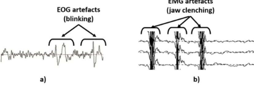
Part of the EEG signals comes from electrical activity unrelated to the brain: muscular activity of the head and neck, eye movements which are equivalent to rotating electric dipoles, eye blinks which generate electric charge variations (see Figure 5, for examples of such artefacts). Such biosignals can of course provide useful information (indicating discomfort, or attention lapses). One should be aware of these artefacts and be careful not to process them indistinctly from brain signals, for BCI that aims to process information coming strictly from the brain [30].
Figure 5: Examples of artefacts polluting EEG signals. a) Electrooculographics (EOG) artefacts due to blinking, b) Electromyographic (EMG) artefacts due to jaw clenching.
Detecting artefacts can be done with amplitude thresholds on bandpower (muscular artefacts) or time-courses of certain channels. For ocular artefacts, additional electrodes can be placed close to the eyes, allowing to recognise a trace of that activity on the EEG channels.
Once an artefact has been detected, the portion of data corrupted with this artefact should be rejected (i.e. disregarded) in two cases: 1) if the effect of the artefact on the rest of the signal is too strong to be removed; 2) if the artefact indicates that correct conditions are not met for pursuing with the BCI at that particular time. In other cases, one can subtract the effect of the artefact from the EEG by using special techniques such as Independent Components Analysis or specific filters [57].
EEG signals can be represented in three different domains: in time (as they are acquired by the amplifier), in frequency (spectral power) and in space (topo-graphical layout on the scalp according to the electrode positions, as in Figure 3). Time-based representations are especially useful when dealing with event-related potentials (ERPs). ERPs come with time triggers (see 2.3), which al-low to extract epochs, which are time-windowed portions of signals. The EEG measures a mixture of activities coming from many regions of the brain, and although ERPs are stereotyped deflections, they are difficult to distinguish in a single epoch. Statistical procedures are called for to extract the significant deflections from several epochs (or trials). The simplest statistical procedure is cross-trial averaging: this decreases the amplitude of the background oscil-lations, whose phase is not consistent across the trials. For Brain Computer Interfaces where the analysis must be done in real time, there are specific tech-niques for single-trial detection of ERPs (see 3.2.2).
Frequency-based representations reveal the spectrum of the EEG, and can be applied on sliding windows: such time-frequency representations are necessary for BCI real-time processing. Since relevant brain activity is often frequency-dependent (e.g. ERD/ERS reviewed in part 2.2), it is useful to band-pass filter the signals to the frequency-bands of interest. This also reduces the influence of noise coming from other frequencies, e.g. power-line noise.
Spatial representations reveal spatial patterns, also called topographies, related to the brain areas where the activity is produced. In order to enhance the signal to noise ratio, some spatial processing can be applied to the EEG. In-deed, electric fields on the scalp result from electrical conduction within the head volume. Because the skull is a poor electrical conductor, scalp topographies are blurred compared to the distribution of cortical sources. Source reconstruction, through an inverse problem, allows to pinpoint the activity of interest at the cortical level [58]. BCI features can then be defined in source space [59, 60], allowing to make use of a priori information. For instance, detection of an error-related potential is facilitated by only considering the source activity originating from the anterior cingulate cortex. However, rather than source space analy-sis, simpler spatial filters, known as Laplacian filters, are more commonly used. The Laplacian enhances the SNR of the data, by bringing out the differences between neighboring electrodes. In fact, the Laplacian filter crudely approxi-mates source reconstruction: it performs a deconvolution of the blurring due to volume conduction [61, 62].
3.2
Feature extraction
As mentioned before, feature extraction aims at representing raw or prepro-cessed EEG signals by an ideally small number of relevant values, which describe the task-relevant information contained in the signals. These features should be selected to minimise the intra-class feature variances while maximising inter-class variances. In other words, their values should be as different as possible between different classes. BCI based on oscillatory activity (e.g., BCI based on ERD/ERS or SSVEP) mostly use spectral and spatial information as features whereas BCI based on ERP mostly use the temporal and spatial information. The next sections detail the corresponding feature extraction tools for these two categories of BCI.
3.2.1 EEG signal processing tools for BCI based on oscillatory ac-tivity
Oscillatory activity-based BCI are based on changes in power in some frequency bands, in some specific brain areas. They naturally need to exploit both the spatial and spectral information. As an example, a basic design for a motor-imagery BCI would exploit the spatial information by extracting features only from EEG channels located over the motor areas of the brain, typically chan-nels C3 for right-hand movements, Cz for feet movements and C4 for left-hand movements. It would exploit the spectral information by focusing on two fre-quency bands µ (8 − 12 Hz) and β (16 − 24 Hz). More precisely, for a BCI that can recognise left hand MI versus right hand MI, the basic features extracted would be the average power in µ and β bands from both channels C3 and C4. Therefore, the EEG signals would be described by only 4 features.
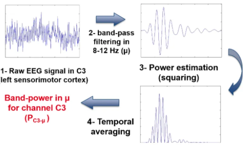
There are many ways to compute band power features from EEG signals [63, 64]. However, a simple one is to first band-pass filter the EEG signal from a given channel into the frequency band of interest, then to square the resulting signal to compute the signal power, and finally to average it over time (e.g., over a time window of 1 s). This is illustrated in Figure 6.
This basic design is unfortunately far from being optimal. Indeed, it uses only two fixed channels and two fixed frequency bands. As such, relevant infor-mation, from other channels or frequency bands, might be missing, and these two channels and bands may not be the best for the target subject. In general, better performances are obtained by using more channels [65, 66]. However, using more channels means extracting more features, thus increasing the di-mensionality of the data, making the classifier optimisation more difficult. To efficiently deal with multiple channels, one can perform 1) Feature selection to automatically select a subset of relevant features [67]; 2) Channel selection to select automatically a subset of relevant channels, among all channels available [66] or 3) Spatial Filtering to combine several channels into a single one, from which features will be extracted. For EEG signal classification, spatial filtering is one of the most efficient and popular approaches [68]. It defines a smaller number of new channels as linear combinations of the original ones:
Figure 6: Signal processing steps to extract band power features from raw EEG signals. The EEG signal displayed here was recorded during right hand motor imagery (the instruction to perform the imagination was provided at t = 0 s on the plots), on electrode C3 (located over the left sensorimotor cortex), for 1 second. The contralateral ERD during imagination is here clearly visible in the last half of the signal. Indeed, the signal power in channel C3 (left motor cortex) in 8-12 Hz clearly decreases while the subject imagines a right hand movement.
˜
x(t) =X
i
wixi(t) (1)
with ˜x(t) the spatially filtered signal, xi(t) the EEG signal from channel i
at time t and wi the weight given to that channel in the spatial filter. Spatial
filtering is not only useful because it reduces the dimensionality of the prob-lem, but also because it can reduce spatial blur due to volume conduction as mentioned in Section 3.1.
For BCI based on oscillatory EEG activity, the gold-standard in spatial filter-ing is a supervised algorithm (i.e. an algorithm that uses trainfilter-ing data labelled with their classes) known as the Common Spatial Patterns (CSP) algorithm [68, 69]. Informally, the CSP algorithm finds spatial filters w that maximise the variance of the filtered signal for one class and minimise it for the other class. Since the variance of a band-pass signal is actually the band-power of this signal, this means that CSP finds spatial filters that lead to maximally discrim-inant band-power features since their values are maximally different between classes. In [70], it was shown that “for two-class paradigms CSP maximizes an approximation of mutual information of extracted EEG components and class labels”. As such, CSP is particularly useful for BCI based on oscillatory activity, in which the relevant features are band-power features. As an example, for BCI based on motor imagery, EEG signals are typically filtered in the 8− 30 Hz band before being spatially filtered with CSP [69]. Indeed this band contains both
the µ and β rhythms. Formally, CSP uses the spatial filters w which extremise (i.e. maximise or minimise) the following function:
J (w) = wX1X
T 1wT
wX2X2TwT
(2) which is equivalent to extremising
JCSP(w) =
wC1wT
wC2wT
(3) where T denotes transpose, Xi is the training band-pass filtered signal matrix
for class i (with the samples as columns and the channels as rows) and Cian
es-timate of the spatial covariance matrix from class i. In practice, the covariance matrix Ciis usually estimated as the average covariance matrix of each trial from
class i from the training set [68]. In this equation, wXi is the spatially filtered
EEG signal from class i, and wXiXiTwT is thus the variance of the spatially
filtered signal, i.e., the band-power of the spatially filtered signal. Therefore, extremising JCSP(w), i.e., maximising and minimising it, indeed leads to
spa-tially filtered signals whose band-power is maximally different between classes. JCSP(w) happens to be a generalized Rayleigh quotient. Therefore,
extremis-ing it can be solved by Generalized Eigen Value Decomposition (GEVD). The spatial filters w that maximise or minimise JCSP(w) are thus the eigenvectors
corresponding to the largest and lowest eigenvalues, respectively, of the GEVD of matrices C1and C2. Typically, 6 filters (i.e., 3 pairs), corresponding to the 3
largest and 3 lowest eigenvalues are used. Once these filters have been computed, a CSP feature f is defined as follows:
f = log(wCwT) (4)
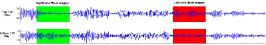
i.e., the features used are simply the band power of the spatially filtered signals. The use of CSP is illustrated in Figure 7. In this figure, the signals spatially filtered with CSP clearly show differences in variance (i.e., in band power) be-tween the two classes, hence ensuring high classification performances. It is worth mentioning that the spatial filters w are only filters, and not the scalp to-pographies of the corresponding brain sources. As such the spatial filter weights should not be interpreted from a neurophysiological point of view [71]. Indeed, spatial filters can be seen as an unmixing or inverse model, whereas the forward or mixing model is the one that should be neurophysiologically interpreted. To go from the spatial filters (backward model) to the spatial patterns (forward model), i.e., to the scalp topography of the corresponding brain sources, one should work with the spatial patterns matrix A = (W−1)T with W the matrix
with the w as columns [68, 71]. The spatial patterns, i.e., the columns of A, are the scalp topographies of the brain sources targeted by the spatial filters W .
As mentioned above, CSP is a gold standard algorithm for BCI based on oscillatory activity. Nonetheless, CSP has been shown not to be very robust to noise, non-stationarities and artefacts and to be prone to overfitting (i.e.,
Figure 7: EEG signals spatially filtered using the CSP (Common Spatial Pat-terns) algorithm. The first spatial filter (top filter) maximises the variance of signals from class “Left Hand Motor Imagery” while minimising that of class “Right Hand Motor Imagery”. It corresponds to the largest eigenvalue of the GEVD. The last filter (bottom filter) is the opposite: it maximises the variance of class “Right Hand Motor Imagery” while minimising that of class “Left Hand Motor Imagery” (it corresponds to the lowest eigenvalue of the GEVD). This can be clearly seen during the periods of right or left hand motor imagery, in green and red respectively.
it may not generalise well to new data) when little training data is available [70, 72, 73]. As such, many CSP variants have been designed to make it more robust to noise and non-stationarities [74, 75], or to enable it to optimise both spatial and spectral filters at the same time [76, 77].
3.2.2 EEG signal processing tools for BCI based on event related potentials
Like BCI based on oscillatory activity, BCI based on ERP can exploit the spatial information in EEG signals. This is typically done by focusing mostly on some specific electrodes (i.e., by extracting features only for these electrodes), e.g. for the P300, by using only electrodes located over the parietal lobe, where the P300 is known to originate. As an example, Krusienski et al. recommend to use a set of 8 channels, in positions Fz, Cz, P3, Pz, P4, PO7, Oz, PO8 [78].
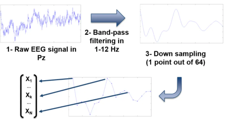
Once the relevant spatial information has been identified, using, for instance, only the electrodes mentioned above, features can be extracted for the signal of each of them. For ERP in general, including the P300, the features generally exploit the temporal information of the signals, i.e., how the amplitude of the EEG signal varies with time. This is typically achieved by using the values of preprocessed EEG time points as features. More precisely, features for ERP are generally extracted by 1) low-pass or band-pass filtering the signals (e.g., in 1-12 Hz for the P300), 2) downsampling the filtered signals, in order to reduce the number of EEG time points and thus the dimensionality of the problem and 3) gathering the values of the resulting EEG time points from all considered channels into a feature vector that will be used as input to a classifier. This process is illustrated in Figure 8, for feature extraction from channel Pz in a P300-based BCI experiment.
Figure 8: Typical process to extract features from a channel of EEG data for a P300-based BCI design. On this picture we can see the P300 becoming more visible with the different processing steps.
per channel and many channels used. As such, tools such as feature selection or spatial filtering can also benefit ERP-based BCI design. Regarding spatial filtering, some groups have proposed spatial filters dedicated to the classification of ERPs, leading to maximally discriminant ERP features [79, 80]. One of them is the xDAWN spatial filter [80]. This spatial filter aims at maximising the signal-to-signal-plus-noise-ratio. Informally, this means that xDAWN aims at enhancing the ERP response, at making the ERP more visible in the middle of the noise. Formally, xDAWN finds spatial filters that maximise the following objective function:
JxDAWN=
wADDTATwT
wXXTwT (5)
where A is the time course of the ERP response to detect for each channel (estimated from data, usually using a Least Square estimate) and D is a ma-trix containing the time triggers of the target stimuli evoking the ERP. In this equation, the numerator represents the signal, i.e., the relevant information to enhance. Indeed, wADDTATwT is the power of the time course of the ERP
re-sponses after spatial filtering. On the contrary, in the denominator, wXXTwT
is the variance of all EEG signals after spatial filtering. Thus, it contains both the signal (the ERP) plus the noise. Therefore, maximising JxDAWN actually
maximises the signal, i.e., it enhances the ERP response, and simultaneously minimises the signal plus the noise, i.e., it makes the noise as small as possible [80]. This has indeed been shown to lead to much better ERP classification performance, especially when little training data was available.
3.3
Pattern recognition
The pattern recognition stage aims at predicting a value from which infering the user’s current brain activity pattern. It uses as input some features or patterns extracted from brain signals such as the power in specific frequency bands or a smoothed signal segment (see 3.2). Predicting a discrete variable corresponds to a classification task while predicting a continuous variable corresponds to a regression task.
Classification consists first in learning an efficient function f from a training set of N labelled examples {(d1, c1), (d2, c2), ..., (dN, cN)} where dn is a feature
vector and cnis its associated class, to allow to assign a new feature vector d to
a unique class c = f (d) among C. When C only has 2 elements, the classifica-tion is binary. Numerous machine learning techniques, such as support vector machines, neural networks or logistic function, can perform this task. If C contains more than 2 classes, there are two possible approaches to obtain a clas-sification function [81, 82]. The first approach consists in directly estimating the class using multiclass techniques such as decision trees, multilayer perceptrons, naive Bayes classifiers or k-nearest neighbours. The second approach consists in decomposing the problem into several binary classification problems. This decomposition can be done in different ways using i) one-against-one pairwise classifiers [83, 84], ii) one-against-the rest (or one-against-all) classifiers [84], iii) hierarchical classifiers similar to a binary decision tree and iv) multilabel clas-sifiers [85, 84]. In the later case, a distinct subset of L labels (or properties) is associated to each class. The predicted class is identified according to the closest distance between the predicted labels and each subset of labels defining a class.
The performance of the classification function f can be evaluated using dif-ferent statistical measures. The most popular measure is the accuracy which measures the percentage of correct recognition. The accuracy is sensitive to the number of classes. The Cohen’s Kappa coefficient κ is a performance measure which takes the number of classes into consideration. However, these measures do not distinguish types of error. Indeed, when the classifier assigns a feature vector (or pattern) to class A whereas it actually belongs to class B, this error has the same cost as the opposite error. In many applications, these two types of error (namely type I and II in statistical hypothesis testing) do not have the same impact. As an example, if the detection of an ERP triggers the writing of a letter, it can be more acceptable for the system not to write a letter but instead to wait for more data in order not to write an erroneous letter.
To get a detailed measure of types of error, it is possible to build a confusion matrix. This 2D-table reports how many patterns from each class (true label) have been assigned to which class (estimated label). The occurrences in the di-agonal correspond to the correct assignments. Occurrences outside the didi-agonal correspond to different types of errors. If it is more important to take care of the performance of a specific class (named P as positive), it is possible to compute the recall (or sensitivity) and the precision of the classification function for this
class. Correctly classified patterns of this class are called True Positives (TP) because the specific class to look at is identified as the positive one, and the other classes are identified as the negative ones. The recall is computed as the ratio of TP to the total number of patterns of class P. This measure indicates how good the function is at identifying patterns of class P. Nevertheless, a good value can be due to a biased classifier which excessively assigns any pattern to class P. So, it is also useful to measure the precision which corresponds to the ratio of TP to the number of patterns assigned to class P. Patterns incorrectly assigned to class P are called False Positives (FP). Patterns of class P assigned to another class are called False Negative (FN) and patterns of other classes than P not assigned to class P are called True Negatives (TN). In theory, both the recall and the precision rates are useful. The F-score combines these two measures in one.
Here is a summary of the statistical measures presented above: • accuracy = (T P + T N )/(T P + F P + F N + T N );
• κ = (accuracy - probability of random agreement)/(1 - probability of ran-dom agreement);
• recall (or sensitivitxy) = T P/(T P + F N ) (or true positive rate); • specificity = T N/(F P + T N ) (or true negative rate);
• precision = T P/(T P + F P ); • F-score = 2×recall×precision
recall+precision .
In practice, it is unfortunately frequent that the recall and the precision cannot both be close to one. Thus, according to the application, it is sometimes better to favour a high recall (e.g. detection of ErrP, see section 2.3) or a high pre-cision (e.g. detection of ERP). The Receiver Operating Characteristic (ROC) curve is used to observe the effect of the decision threshold on the sensitivity and specificity. The surface of this curve is also used as an indicator to evaluate classifier performance and to compare classifiers. Indeed, many different ma-chine learning techniques exist for classification. The most used in BCI are the Linear Discriminant Analysis (LDA) and the Support Vector Machines (SVM), for their capabilities to obtain a robust classifier i.e. efficient with new pat-terns. LDAs are simple linear models which do not require any hyperparameter [20]. SVM are linear or non-linear models, depending on the selected kernel, that maximise the distance between the decision boundary and the patterns of each class [20]. Robustness, or generalisation capability, is an important issue. The classification function learned during the calibration phase must be effi-cient with new patterns. Thus, the classification function is evaluated using the statistical measures presented above on a subset of labelled patterns acquired for calibration. If the dataset is large, the evaluation can be done using only one subset. When it is small, a cross-validation procedure is used for which the labelled dataset is split into N folds (e.g. N = 10) [86]. Then the parameters
are computed using N − 1 folds and the classification function is evaluated on the remaining fold. The procedure is repeated 10 times switching the fold used for evaluation. This procedure is only used to estimate the performance of the classifier and avoid overfitting (i.e. a classification function which is good for already known patterns but does not generalise to new patterns). In the end, the classification function is estimated using the entire set of training data. A regularisation term can be added into the cost function to increase the robust-ness of the classification function [87].
Up to now in EEG-based BCI, only a few studies have considered a regression task, i.e. the prediction of a continuous variable, since the low signal-to-noise ratio of EEG signals hinders the prediction of a precise value. The process is quite similar to a classification task. The parameters of a predicting linear or non linear model are learned from a training set where the desired value is continuous. Thus, many machine learning methods have a regression version, e.g. linear regression, multilayer perceptron with a single linear output unit, support vector regression, etc. Nevertheless, different and specific performance measures should be used to assess regression algorithms such as the relative absolute error or the mean square error. These measures estimated the errors between the predicted value and the real one. A regularisation term can also be added to the error function to reduce overfitting. As an illustration, regression as been used in some BCI works aiming at predicting the kinematics of upper [88] or lower limbs [89] from EEG signals.
Currently, a good BCI performance is essentially defined as a high classifica-tion accuracy. As discussed above there are various measures associated to the performance of a classifier such as the surface under the ROC curse, the F-score or the Kappa value [90]. But other measures are associated to the final task such as the accomplishment (success/fail) or speed (duration to reach a target, reaction time, Information Transfer Rate, characters per minute) [91]. Thus, although many metrics exist, one must question what they really mean for the user? Is she/he able to keep them stable or to improve them? Does she/he use a trick to control the BCI such as muscular artifacts or other brain areas than the ones expected? Is she/he able to use the BCI for a long time, without a long calibration time, without fatigue and with satisfaction? Therefore, numer-ous metrics beyong statistical measures should also be considered to evaluate a BCI system, e.g., measures including the users experience and preferences as measures with questionnaires.
3.4
Feedback
Designing a reliable BCI requires to consider its two main components, the user and the machine. BCI should be seen as a co-adaptive system [6], with the user learning to produce EEG patterns that can be recognised by the machine, and the machine learning to recognise such patterns. Indeed, BCI control is known to be a skill that needs to be learned and mastered by the user [6, 22].
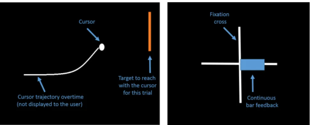
This is notably essential for spontaneous BCI, that is, BCI based on spon-taneously generated brain activity patterns (e.g., motor imagery-based BCI). Indeed, ERP-based BCI require very little user training [92]. The fact that spontaneous BCI control is a skill means that 1) the BCI performances of a user become better with practice and thus that 2) the user needs to learn how to produce stable, clear and distinct brain activity patterns to successfully con-trol a BCI. A key and necessary element for successful learning of spontaneous BCI control skills is the feedback provided by the machine to the user about his/her brain activity, i.e., about the mental command recognised by the BCI [22, 93, 94]. Typically, this feedback takes the form of a visual cursor or a bar moving on screen according to the recognised brain activity pattern (see Figure 9).
Figure 9: Examples of BCI feedback for BCI based on sensorimotor rhythms. Left: continuous cursor feedback, the cursor continuously moving from left to right, its vertical position being modulated by the sensorimotor rhythms ampli-tude [7]. Right: bar feedback, a bar is continuously extended towards the left or right, depending on whether the recognised EEG pattern was left or right hand movement, respectively. The bar length is proportional to the absolute classifier output [37].
However, how to train users to control BCI has been rather scarcely studied in the BCI literature so far, and the best way to train users to master BCI control skills is still unknown [28, 22]. It is estimated that, with current systems, 10 to 30% of BCI users cannot reach BCI control at all (so-called BCI deficiency) [28]. Currently used standard training tasks and feedback are extremely simple, based on heuristics, and provide very little information. It has been shown that such standard training approaches are most likely very suboptimal with respect to general human learning and education principles [93]. For instance, typical BCI feedback is only corrective i.e., it only informs the user whether he/she performed the mental tasks correctly, whereas human learning principles recommend to provide an explanatory feedback, indicating what was right or wrong about the task performed. Therefore, there is still a need for further
research efforts to design an ideal BCI feedback and training environment [33].
4
Applications
Once the BCI is able to recognise the user’s brain activity patterns, it can be used to send commands to an application. Below we present some of the main applications in which BCI can be used.
4.1
Spellers
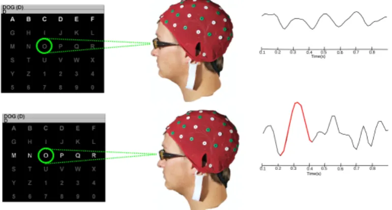
Several BCI systems, called “spellers” have been proposed for typing sentences without muscular control, thus eliciting communication for severely disabled patients. The most successful of these spellers is called the P300 speller [10]. The P300 speller has the advantage not to require any training on the part of the user, whose task is to concentrate his/her attention on the symbol he/she wants to type. The P300 speller can predict the symbol on which the user’s attention is focussing, because flashing this symbol elicits an ERP in the EEG, the so-called P300 wave. Figure 10 illustrates the P300 speller principle.
Figure 10: This user wants to type the letter “O”: he counts the number of times it flashes on the screen, as in the lower picture. Each flash of the target letter creates an Evoked Response Potential, the P300 wave, time-locked to the flash display.
The BCI system has to be calibrated to detect the P300 wave from the background EEG (see section 2.3). To accelerate the throughput, keyboard symbols are organized in groups that flash simultaneously. The original P300 had a row-column flashing strategy [10], but groups can be arranged in other patterns, e.g. to minimize the probability of a given symbol flashing twice in
a row [95]. Indeed, double flashes are both uncomfortable for the user, and produce a reduced P300 evoked response for the second flash.
The way a symbol is flashed generally consists of increasing its visual contrast with the background, and also increasing its size. Recent findings by Jin et al. show that the P300 signal-to-noise can be increased by replacing the symbols with pictures such as famous faces during the flashing interval [96].
The signal-to-noise ratio of a P300 wave is low, so sequences of flashing sym-bols must be repeated to make its detection possible. Each group of symsym-bols is generally flashed several times. Besides, users are generally asked to count the number of flashes of their desired symbol in order to engage their atten-tion. Modern P300 systems now use early stopping of the flashes as soon as a reliable decision has been made [97]. Early stopping increases the throughput, while improving users’ motivation, whose focussed attention is rewarded by a faster decision [98, 99]. In spite of the progress made in this application, it can take several seconds for a user to type a symbol with the P300 speller. Word prediction engines can be combined with the speller, to make the typing more efficient [100].
Of course, the P300 spellers can be adapted to any task relying on a choice among several elements. BCI games have been developed using this principle (see section 4.5).
A few other BCI spellers are based on other neurophysiological features than the P300. The commercial Intendix system http://www.intendix.com/ can be operated either with a P300 or an SSVEP. The Hex-O-Spell [101] uses self-paced MI features to control a rotating arrow, allowing to point to the desired letter (in two steps, each with only 6 choices).
Flashing, or even displaying symbols on a screen may not be appropriate for all users, say in the case of visual deficiencies [102]. Auditory P300 spellers have been developed,whose throughput is generally lower than for visual P300 spellers, because less symbols can be presented simultaneously to the user [103]. When hardware becomes easier to handle and to set up, BCI spellers could become commonly used by individuals with severe neuromuscular disabilities, such as amyotrophic lateral sclerosis (ALS). Several clinical studies have in-deed demonstrated the usability of the spellers [104, 99], for patients who are able to maintain a sustained attention [105], and regular home use has been reported [106].
4.2
Motor substitution
A neuroprosthesis is a prosthesis attached to the (central or peripheral) nervous system [107]. A prosthesis is a device for improving or replacing a defective organ or a missing body part. Auditory and visual prostheses are neuroprostheses that build an alternative pathway from stimuli to the brain. In this section we will focus on motor prostheses that build an alternative pathway from brain signals or electrical nerve impulses to an artificial limb or to muscles (using functional electrical stimulation). In case of spinal cord injury, amyotrophic lateral sclerosis or brainstem stroke, the pathway from brain to muscles is interrupted before
the nerve fibers. The activity of the motor cortex is then analysed to decode the intention of movement. Using multielectrode arrays placed invasively in the primary motor cortex, it is possible to decode the direction of movement from the activity of a neural population [108] and send commands to a robotic limb or an exoskeleton to reach and grasp a target [109]. Electrocorticography electrodes placed on the cortex are also used to obtain a good enough quality of signals, less invasively than microelectrode arrays which can cause brain tissue damage. Non-invasive signals such as EEG are also used in neuroprosthetics [12] although the spatial resolution is low and the signals are noisy. Thus, P300 wave and SSVEP can be used for a control task [50]. But ERD is most commonly used to detect a desynchronisation in various parts of the cortex meaning that a specific mental task is performed. As an example, each mental task can be translated into a command for a wheelchair in a shared-control with an obstacle avoidance system [110, 111]. Motor imagery tasks are often used to control neural prosthesis or to trigger a functional electrical stimulation system [112, 113]. It should be noted, however, that designing neuroprostheses for the lower limb is still a challenge [114], notably due to the lack of tactile or proprioceptive feedback to the user. Therefore, current efforts are focussed on adding stimulations in the somatosensory cortex or on the skin of user to provide him/her with tactile feedback and therefore to obtain a complete action-perception loop.
4.3
Stroke rehabilitation
A stroke (cerebral infarction or cerebral haemorrhage) is a severe common brain disorder which causes many situations of disability. Stroke is the second lead-ing cause of death and the third leadlead-ing cause of disability-adjusted life-years (DALYs) worldwide [115]. Its incidence has increased over the last two decades. One year after the accident, 30% of stroke patients do not survive. 60% of the survivors recover functional independence while about 40% are left with significant disabilities, limiting their independence in their daily lives. The ma-jority of patients more or less recover the ability to walk, but motor control of the arm and hand often remains impaired. To limit this loss of motor control, brain-computer interfaces can be used to propose to stroke patients with resid-ual corticomotor patterns, exercices with various feedbacks (gauge, virtresid-ual limb, robotised arm, or even functional electrical stimulation of the real limb). These exercices aim at guiding brain plasticity towards restoring efficiently and effec-tively motor control, or improving the control of a neuroprosthesis if not enough motor control can be recovered [16, 116, 17]. Indeed, non-invasive brain imaging techniques (fMRI, PET) and electrophysiology (TMS, EEG, MEG) can help to better understand and exploit the plasticity of the motor cortex and implement appropriate strategies for rehabilitation [117].
Recently, several groups have indeed shown that BCI-based stroke rehabil-itation was possible and successful, e.g. [118, 119, 120, 121]. While these are still relatively recent results, they are very promising and need to be further explored in particular to rigorously evaluate the BCI intervention versus or in
addition to a physical therapy using for example randomized controlled trial.
4.4
BCI and disorder of consciousness
Another medical area in which BCI has recently proved to be a promising tool is for patients with Disorders of Consciousness (DoC). Indeed, following a traumatic incident or a stroke, some patients may be believed to be in a non-responsive or vegetative state (i.e., with DoC), as they show no behavioral markers of consciousness. However, some of these patients may actually be con-scious or partially aware, but unable to express and show it as they are in a locked-in state. For these patients that have been erroneously diagnosed with DoC, BCI can be used to diagnose their consciousness even in the absence of any behavioural response. To do so, these patients may be asked to control a given BCI, such as a motor-imagery BCI [122], or a P300-based BCI [123]. If the patient manages to control the BCI, i.e., if the patients’ EEG signals can be discriminated according to the instructions, it means the patient can cogni-tively respond (by performing motor imagery tasks or by attending stimulus) and therefore that he/she is conscious. If this is the case, the patient can then use the same, or another BCI to communicate with his/her environment [124]. Interested readers can refer to [125] for a review of the works in this direction and to [126] for some perspectives and challenges to tackle to bring BCI for DoC into practical clinical contexts.
4.5
Gaming and Virtual Reality
As mentioned earlier, potential BCI applications are far from only targeting severely motor impaired users, and can also benefit healthy users [127]. BCI can notably be seen as an exciting alternative or complementary way to control video games [128, 14, 129] and/or other virtual reality (VR) applications [13, 130]. For instance, BCI can enable a gamer to select objects in the game simply by paying attention to them [131, 132, 133]. In this case, a specific visual stimulus is displayed in overlay of each object, in order to evoke P300 or SSVEP responses. For instance, a BCI version of the popular “connect-4” game was proposed based on the P300 response [134]. In this game, the players could select the column in which to insert their token thanks to P300-based selection of the flashing columns. BCI can also be used to perform navigation tasks in game virtual environments VE [135, 136, 137, 138, 139]. This can be achieved for instance by performing left hand, right hand and foot MI to turn left, right and go forward respectively [135, 139, 136] or by paying attention to flickering control buttons overlayed to the game, each button evoking a different SSVEP response and being associated to a different displacement direction in the game [138, 140]. In all these BCI-based video games prototypes, the BCI was the sole input device. However, current BCI typically provide a rather limited number of commands (typically between 1 and 3 - with substantially lower accuracy with higher number of commands), and thus provide a limited interaction with the game. An interesting approach is therefore to use the BCI as a complementary
input device: most of the game is controlled using a traditional input device such as a game pad, and only some actions, e.g., special powers, are controlled using the BCI. This was explored in the alphaWoW (alpha World of Warcraft) game, in which the player’s avatar in the WoW game was controlled using a game pad, and this avatar can turn from a brutal bear into a fragile elf depending on the player’s relaxation level, as measured in his/her EEG signals in the alpha band [141].
4.6
Mental state monitoring and passive BCI
Most, if not all, of the BCI-based systems and applications described so far were systems for communication and control, in which the user was voluntarily sending mental commands to the application. These types of BCI are known either as active BCI, when the user performs mental tasks (e.g., motor imagery), or as reactive BCI, when the users have to attend to stimuli (e.g., P300 or SSVEP-BCI) [15]. There is yet another category of BCI: passive BCI, for which the mental state of the user is passively estimated, without any voluntary mental command from the user, in order to adapt the application in real-time to this mental state [15]. For instance, some passive BCI can be used to monitor vigilance/alertness levels of operators performing repetitive tasks, such as x-ray luggage controllers in airports [142]. Detecting lapses of attention reduces the risk of missing threats, and can be used to propose a break to tired operators. Another example would be a passive BCI used in a car, to detect emergency braking intentions. Emergency braking intentions can indeed be detected in EEG signals before the actual physical braking, hence making it possible to stop the car earlier, potentially avoiding an accident [143]. Note that in this specific case, the used BCI design and signal processing approach are similar to that of active BCI based on movement onset detections. However, in the case of emergency braking intentions, the user does not have to do anything specific to control the BCI: he/she is driving his/her car normally, while his/her brain activity is passively monitored to detect emergency braking intention. There are actually increasingly more passive BCI application prototypes being proposed, and which were reviewed in [144, 15]. Indeed, a number of interesting mental states can be estimated, more-or-less reliably, in EEG signals, such as mental workload (i.e., pressure on the user cognitive resources, e.g., working memory) [145, 146], attention [142, 147] and, though less accurately, emotions [148], among others [149]. Being able to monitor continuously such mental states from EEG signals makes it possible to design applications that adapt to such mental states, to provide an improved user experience [150] or simply to assess the ergonomic qualities of the system [151, 152], among many potential applications.
5
Hardware and software platforms for BCI
In addition to selecting the specific brain signals, signal processing algorithms and feedback to use for the targeted BCI-based application, a BCI designer must also make practical and technical choices regarding hardware (choice of EEG sensors) and software (choice of real-time BCI software platform).
At the hardware level, one must consider what type of EEG electrodes and associated amplifier to use. In particular, EEG electrodes can either be gel-based, wet or dry. Gel-based electrodes use conductive gel or paste between the EEG sensors and the scalp, in order to reduce impedance and obtain good quality signals [153] (see also Section 2.1). Most BCI systems described in the literature use gel-based electrodes with medical-grade EEG amplifiers, which is the configuration providing the best signal quality so far. However, the use of gel makes the system long to setup and rather cumbersome for the user, who will have to wash his/her hair after each use. Alternative EEG sensors, which do not require gel, are currently being developed. For instance, wet electrodes only require to soak the sensor in a liquid solution, or dry electrodes do not require any gel nor solution, and can thus be used immediately [154]. Several dry EEG sensors have been recently developed or are currently being developed with interesting results [155, 156]. These dry sensors are now able to acquire good quality EEG, and are much faster to setup than gel-based systems, at the cost of still more sensitivity to environmental noise and artifacts, notably artefacts due to the user’s motion. These last years have also witnessed the advent of consumer grade EEG devices, such the Neurosky Mindwave (http://neurosky. com/) or the Emotiv Epoc (www.emotiv.com). These EEG devices are cheap (e.g., about $ 300 for the Emotiv Epoc), do not use gel (they use either wet or dry EEG sensors) and have an attractive design. They have therefore contributed to making BCI design and use more popular and widespread. However, these devices provide lower quality EEG signals [157], and are notably sensitive to facial EMG artefacts due to their use of multiple electrodes located near the neck, on the forehead or over temporal locations [158]. Using them therefore requires taking extra care to ensure that the signals are not corrupted with undesired EMG artefacts.
On the software side, there are now a handful of mature and open-source soft-ware solutions for the design of real-time EEG-based BCI, see [159] for a recent overview. The two most widely used are BCI2000 [160] (http://bci2000.org) and OpenViBE [161] (http://openvibe.inria.fr). These two software plat-forms come with a number of ready-made BCI scenarios (motor imagery-based BCI, P300-speller, etc.), a number of widely used EEG signals processing and classification algorithms, and support an increasing number of EEG acquisition devices. These two software are now both open-source, which makes them easily customisable and extensible, with a large community of users. An interesting initiative to mention is also the TOBI interfaces, which are software components to enable different BCI software platforms to be connected to each other and thus to benefit from each other functionalities [162].