HAL Id: cea-01840789
https://hal-cea.archives-ouvertes.fr/cea-01840789
Submitted on 16 Jul 2018
HAL is a multi-disciplinary open access
archive for the deposit and dissemination of
sci-entific research documents, whether they are
pub-lished or not. The documents may come from
teaching and research institutions in France or
abroad, or from public or private research centers.
L’archive ouverte pluridisciplinaire HAL, est
destinée au dépôt et à la diffusion de documents
scientifiques de niveau recherche, publiés ou non,
émanant des établissements d’enseignement et de
recherche français ou étrangers, des laboratoires
publics ou privés.
Intracavitary in vivo dosimetry based on multichannel
fiber-coupled Radioluminescence and Optically
Stimulated Luminescence of Al_2O_3 :C
Estelle Spasic, Sylvain Magne, Isabelle Aubineau-Lanièce, Loïc de Carlan, C.
Malet, C. Ginestet, Pierre Ferdinand
To cite this version:
Estelle Spasic, Sylvain Magne, Isabelle Aubineau-Lanièce, Loïc de Carlan, C. Malet, et al..
Intra-cavitary in vivo dosimetry based on multichannel fiber-coupled Radioluminescence and Optically
Stimulated Luminescence of Al_2O_3 :C. Int. Conf. on Advancements in nuclear
instrumenta-tion, measurement, methods and their applications (ANIMMA), IEEE, Jun 2009, Ghent, Belgium.
�10.1109/ANIMMA.2011.6172964�. �cea-01840789�
978-1-4577-0927-2/11/$26.00 ©2011 IEEE
Intracavitary In Vivo Dosimetry based on
Multichannel Fiber-Coupled Radioluminescence and
Optically Stimulated Luminescence of Al
2
O
3
:C
E. Spasic, S. Magne, I. Aubineau-Lanièce, L. de Carlan, C. Malet, C. Ginestet and P. Ferdinand
Abstract– Fiber Optic Dosimetric Catheters (FODCs) composed of chains of alumina crystals are investigated by the CEA LIST within the French ANR-INTRADOSE Project in the purpose of intracavitary in vivo dosimetry (IVD) during Brachytherapy (BT) with iridium sources and Intensity-Modulated Radiation Therapy (IMRT) with linear accelerators. A dedicated process involving PMMA fibers, casted altogether forming hexagonal bundle, is demonstrated. Optically Stimulated Luminescence (OSL) signals are recorded on-line after irradiation and absorbed doses are compared to planned dose distribution. Real-time dose measurements may also be performed by recording the RadioLuminescence (RL), spontaneously emitted by the crystals during irradiation. In this case, a correction method is implemented to correct for stem effect influence (Cerenkov and scintillation generated within the fibers). For BT, the dual-fiber subtraction method is used (using a reference fiber) whereas the time discrimination method is used for IMRT. The experimental dose distribution leads to an underestimation of the source-sensor distance presumably due to energy dependence of the alumina crystal at low photon energy. At the time being, Monte-Carlo modeling of the FODC is performed with the aim to estimate this energy dependence and finally correct for it. Finally, metrological and preclinical validations are still running at Centre Léon Bérard (Lyon, France) in the purpose of checking the compliance of the FODC prototypes with treatment specifications and medical constraints.
I. INTRODUCTION
ODAY, more than 50 % of all cancer patients are treated by radiation therapy (RT) alone or in combination with surgery or chemotherapy. External Beam RT (EBRT) treatments involve photon or electron beams delivered by linear accelerators (LINACs). Electron beams are used to treat superficial or shallow tumors close to the skin surface. Photon beams however penetrate more deeply within the human body and overlap significantly with healthy tissues. Therefore, a combination of several beams adequately oriented allows the radiation oncologist to deliver the prescribed dose to the target
Manuscript received May 15, 2011.
E. Spasic, S. Magne and P. Ferdinand are with the CEA, LIST, Laboratoire de Mesures Optiques, F-91191 Gif-sur-Yvette, France. (corresponding author: S. Magne, phone: 33.1.69089047; fax: 33.1.69088395; e-mail: sylvain.magne@ cea.fr).
L. de Carlan, I. Aubineau-Lanièce are with the CEA, LIST, Laboratoire National Henri Becquerel, F-91191 Gif-sur-Yvette, France. (e-mail: loic.lenoir-de-carlan@cea.fr).
C. Ginestet and C. Malet are with the Centre Léon-Bérard, Service de Physique, 28 rue Laennec, F-69373 Lyon, France (email: ginestet@lyon.fnclcc.fr)
volume without exceeding the tolerance for surrounding healthy tissues and organs at risk (OARs) and thus reduce undesirable complications. Treatments are fractionated (dose rate ~ 2 Gy/min, 25 to 35 fractions of 2 Gy depending on the tumor) and for most of them, beams are homogeneous. However, the so-called Intensity-Modulated RT (IMRT) uses multileaf collimators to modulate the beam and sharp dose gradients are generated in the plane of incidence. Another technique that generates high depth-dose gradients (up to 20%.mm-1) is Brachytherapy (BT), on account on inverse
square law and photon attenuation by tissues. It is used for treating localized and small-scale tumors (gynaecologic, prostatic, bronchial, head & neck, breast or esophagic) and involves sources (192Ir, 137Cs, 125I) placed within or next to the
tumor [1-2]. Sources may be placed into natural body cavities (intracavitary) or invasively into solid tissues (interstitial implants). Low-Dose Rate (LDR) BT is usually performed by implanting permanent low-activity seeds into the tumor (mainly 125I). For High-Dose Rate (HDR) and Pulse Dose Rate
(PDR) BTs, a single 192Ir source is used that is connected to a
long cable and unreeled from a remote afterloader. The source is then moved into hollow tubes placed into the patient and its position is computer-controlled. A combination of tubes, dwell times and positions allows the radiation oncologist to deliver the required dose distribution within the tumor. After completion of the treatment, the source is withdrawn. HDR and PDR treatments are fractionated (e.g. 4 fractions of 10 Gy in HDR). In HDR, a high activity source (4 to 10 Ci) is used. It provides a dose rate of ~ 3 Gy/min to 7.5 Gy/min at 1 cm and short treatment time (few minutes).
Treatment Planning Systems (TPS) are used to plan the treatment using morphological data of the patient, obtained by medical imaging methods (X-ray Computed Tomography (CT), Positron-Emission Tomography (PET), Magnetic Resonance Imaging (MRI)). Severe accidents in RT have been associated with the incorrect use of TPS or false dose measurement during its commissioning. In vivo Dosimetry (IVD) is therefore an additional safeguard against major set-up, dose calculation and transfer errors that may be missed when only a pre-treatment verification is performed. IVD is now a legal requirement in France. According to the Code of Practice (CoP) IAEA TRS-398 [3] the difference between planned and delivered doses must remain within typically 2 to 3 %. If the difference exceeds 5 %, the reasons for discrepancy must be investigated and the patient treatment should not be initiated.
In EBRT, dosimeters are placed on the patient skin. Practically, they are mounted into a build-up cap that puts the dosimeter in local electronic equilibrium condition, most often at the position of dose maximum (dmax). The main advantage
of this configuration lies in the low placement-induced uncertainty due to the low dose gradient near dmax.
Furthermore, the shape of the cap may be tailored to provide angular independence which is also a strong request from medical physicists as the dosimeter orientation with respect to irradiation beam is likely to change depending on its placement along the patient’s body. The dose to the tumor is then inferred from surface measurement taking into account the dose distribution given by the TPS. Build-up caps are most often made of metal (brass) in order to reduce shadowing effect (in turn, they become energy-dependent although naked sensors are not). Since the dosimeters are not involved in the dose calculation, their placement into the beam changes the isodose pattern with respect to planned dose distribution (without sensors). Furthermore, IVD is time-consuming. Consequently, IVD is not meant to be used routinely but at the beginning of a new treatment and whenever any change occurs in the treatment planning.
IVD still remains challenging for RT treatments that involve high dose gradients, e.g. Brachytherapy (BT) and Intensity Modulated Radiation Therapy (IMRT). Intracavitary or invasive measurements, close to OARs, must be performed with chains of dosimeters. In this configuration, dosimeters are naturally put in electronic equilibrium by surrounding tissues. However, local unexpected air cavities might disturb the dose distribution with respect to planned calculation.
II. DOSIMETERS FOR INTRACAVITARY IVD
IVD is traditionally provided by ThermoLuminescent Dosimeters (TLDs), RadioPhotoLuminescent Dosimeters (RPL), Metal-Oxide Semiconductor Field-Effect Transistor (MOSFETs) or PN-junction-type diodes [4]. Electronic Portable Imaging Devices (EPIDs) provide portal dose images after transmission through the patient. Back-projection methods are required to retrieve the dose distribution into the patient volume from portal images. Although this method is already used for conventional external beams, it is still challenging in high dose gradient configurations (e.g. IMRT or BT). Therefore, until now, only chains of point dosimeters are used for intracavitary IVD.
MOSFETs have a limited lifetime due to the saturation of threshold voltage (~ 200 Gy), must be frequently recalibrated and show high fading. TLDs necessitate a complex and time-consuming protocol (annealing), somehow simplified by the recent use of RPL. However, these methods do not provide real-time dose monitoring on a routine basis and are costly. Only diodes are widely used in clinical routine on account of their small size and sensitivity and also real-time monitoring capability despite the necessity for correcting the influence of several factors (temperature, dose rate [source-to-surface distance], angular and energy dependencies). Finally, the dose
sensitivity decreases with dose (e.g. -3 %.kGy-1) and periodic
recalibrations are necessary.
Although diodes are widely used in EBRT, chains of diodes are seldom used in intracavitary IVD for several reasons. First, the cable is not radiation-transparent (and disturbs the radiation field). Second, it is bulky (the external diameter of 5-diode rectal probes manufactured by PTW and IBA is 7 mm) and therefore not compatible with insertion within urethras or esophagus. Third, diodes exhibit dose rate and energy dependencies that are difficult to deal with in BT.
Intracavitary IVD is mainly performed with submillimeter-size TLD, RPL or MOSFETs dosimeters inserted within low-diameter catheters (e.g. less than 3 mm). These dosimeters do not provide real-time dosimetry and lead to additional time-consuming and expensive workload associated to maintenance and calibration. Finally, sensor identification is not unmistakable. Present situation is not satisfactory.
The objective of the french ANR-INTRADOSE Project is to perform on-line intracavitary IVD for HDR-BT and IMRT by fiber-coupled RL and OSL dosimetry. This project is managed by the CEA LIST (Saclay, France), in partnership with the Centre Léon Bérard (CLB, Lyon, France), as center of expertise in radiation therapy and the Laboratoire National
Henri Becquerel (CEA LIST LNHB), French National
Metrology Laboratory for ionizing radiation. This paper is dedicated to HDR-BT developments.
III. OSLFIBER OPTICS MULTICHANNEL DOSIMETER AND
SENSORS DEVELOPED WITHIN THE MAESTROPROJECT
Fiber-coupled on-line dosimetry using dosimetric-grade alumina crystals (α-Al2O3:C) has great potential for medical
dosimetry [6-7]. It is investigated at CEA LIST since 1998 [5]. A multichannel OSL Fiber Optics (OSL/FO) reader was designed by the CEA LIST in the framework of the European MAESTRO Project [8] for IVD during radiation therapy treatments [9-11]. It has the capability of measuring dose rates during treatment (time-sampling by the optical switch) and absorbed doses after treatment, without necessity for disconnecting the sensors (on-line readout).
A. OSL/FO sensors
These crystals (grown in reducing atmosphere in the presence of carbon) bring a lot of advantages (high sensitivity, large dynamic range, small fading at room temperature, low Z, etc) [9]-[11]. Alumina pellets or fibers are available at low cost. Fiber crystals were purchased under the trademark TLD500 from Ural State Technical University (Ekaterinburg,
Russia). Alumina pellets were purchased from Landauer Inc. (Chicago, USA) in 2000.
Al2O3:C OSL/FO sensors used within the European
MAESTRO Project were made with polymers and silica fibers. They are small, transparent, radiation-resistant, electromagnetic-immune, in-vivo compatible and low cost. The crystal is affixed onto fiber extremity and protected by a polymer packaging firmly attached to the optical cable.
Previous works have shown that the repeatability in multichannel OSL measurements was typically ± 1 % in reference conditions [9-10]. The energy dependence of the dose response is small (± 0.25 % for electrons over [9 MeV, 18 MeV] and less than 1 % for photons over [6 MV, 20 MV) due to small size of the OSL crystal. Radiation-hard dosimeters with long-term stability of their dose response are desirable in order to avoid frequent time-consuming and costly recalibrations. We have demonstrated that OSL/FO sensors are less prone to radiation damage than semiconductor dosimeters and consequently less costly in consumable (longer lifetime). The reproducibility in dose measurements was kept at ±2 % as the cumulated dose went up to 60 kGy (Gamma-Cell, LNHB).
Preclinical validations of the multichannel unit, software and fiber sensors (TLD500) were performed at Institut Gustave Roussy (IGR, Villejuif) [9]-[11]. Linearity, repeatability, energy and dose rate independence were qualified. Dedicated build-up caps were tested that provide angular independence in the range [-70°, 70°]. Although OSL/FO dosimetry complies with IVD specifications, the readout time is still important (~ 30 seconds per sensor) and the dose range was restricted to 6 Gy. Alumina crystals from Landauer Inc. (Chicago, USA) are now being used for intracavitary IVD because the dose range is compatible with HDR-BT treatments ([0, 13 Gy]) [10].
B. OSL/FO Reader
The OSL/FO reader was already described in previous publications [9-11]. It includes a 16-channel optical fiber switch actuated by a stepper motor, an optical case containing a green-emitting laser, optoelectronics detection devices and power/USB electronics (fig. 1). The reader is linked to a laptop by an USB connection and handled through dedicated software written in LabView. The reader is located in the
control room (next to the irradiation room) and fiber cables run through the wall.
Real-time dose monitoring (RL)
During irradiation, electrons recombine onto recombination centers and generate a Radioluminescence (RL) that may be used for real-time dose monitoring thanks to a proprietary dedicated algorithm.
Cerenkov and scintillation lights are also generated within fibers (stem effect) and superimposed over the useful luminescence signal emitted by the crystals. The Cerenkov emission is due to high-energy secondary electrons propagating into a dielectric medium at a speed faster than speed of light. In usual light guides (refractive index ~1.5), it occurs for electron energy higher than 180 keV and is thus ubiquitous in EBRT treatments involving LINACS but also in BT with iridium sources (mean energy ~ 380 keV).
The time-resolved gating method is well-suited to long-lived scintillators such as Al2O3:C (decay time ~ 35 ms) and provides
an efficient way to get rid of the stem effect but its use is restricted to pulsed sources (e.g. LINACs). Conversely, subtraction methods based on spectral discrimination or
parallel-paired fibers may be used with any radiation source and scintillating material. The subtraction method based on parallel-paired fibers uses a reference fiber (without crystal) placed aside to the sensing one. In EBRT, photon beams extend far into the tissues and depth dose gradients are usually small (less than 0.5 %.mm-1). Conversely, collimators sharply taylor the dose
pattern to the tumor shape thus yielding high lateral dose gradients (i.e. along fiber axis). In this respect, both fibers (sensing and reference) must be accurately matched.
Both methods are investigated by our laboratory. In the context of BT, only the parallel-paired fibers subtraction method can be used and this is performed by dual-channel acquisition and subtraction.
Absorbed dose monitoring (OSL)
After irradiation, each sensor is remotely stimulated using a CW-Diode-Pumped Solid-State laser (@ 532 nm, 200 mW) and bleached for a next use. The reader works in the Continuous-Wave mode (CW-OSL). The OSL stimulation is triggered by an electromagnetic shutter once the switch has moved from its reference position to the selected output. The OSL (@ 410 nm) is then collected by the optical fiber, separated by a dichroïc beam splitter, filtered and eventually detected by a photomultiplier in photon-counting mode. The data counts are corrected for counter dead-time influence (20 ns). The background signal is also averaged from the latest portion of the OSL signal and subtracted from the raw signal. The resulting OSL curve is finally integrated and multiplied by a calibration coefficient to provide the absorbed dose.
Fig. 1. OSL/FO multichannel dosimeter developed by the CEA LIST within the European MAESTRO Project (CEA/C.DUPONT)
IV. FIBER OPTIC OSLDOSIMETRIC CATHETERS FOR
INTRACAVITARY IVD(INTRADOSEPROJECT)
A. Opto-mechanical Design
Fiber Optic Dosimetric Catheters (FODCs) composed of chains of OSL dosimeters must be flexible and their diameter should be less than 3 mm. With this aim in view, PMMA fibers are used instead of silica fibers (N.B.: silica fibers are still used for remote connection outside the treatment room).
FODCs designed by the CEA LIST are composed of 7 PMMA fibers (Ø = 0.5 mm, numerical aperture (NA) = 0.5). One fiber is placed at the centre and serves as mechanical support and also for Cerenkov measurement. Six fibers are assembled around the center fiber according to hexagonal pattern.
FODCs designed for use with LINACs include up to 6 crystals while those designed for use with sealed sources may include up to 4 crystals (3 fibers are used for Cerenkov removal). The crystals are placed along the FODC following helix progression. The external diameter of FODCs is about 2 mm, thus compatible with most stringent intracavitary applications.
These tiny alumina crystals (0.3 x 0.3 x 1 mm3) from
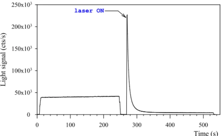
Landauer Inc. are inserted into fiber extremities and epoxy-bonded (fig. 2). Then, SMA-type connectors are mounted onto fiber extremities and the crystals are located onto the external sheath. Each crystal-mounted fibre is tested under a photon beam delivered by X-ray generator (80 keV) and the RL and OSL signals are recorded in order to check for proper coupling of light (fig. 3). The RL is recorded during irradiation. Afterwards, the OSL stimulation is triggered. The readout time for the OSL signal is about 2 min for a stimulation power of 35 mW.
A black paint is sprayed over the fibers in order to prevent light coupling from one fiber to neighbouring ones. Finally, fibers are assembled into bundle, casted within flexible glue and the FODC is protected by an external heat-shrunk polymer sheath (fig. 4). Pb-Sn markers are then deposited outside the catheter in-between successive crystals.
X-ray Radiography (beam energy: 32 keV) is used to check for proper assembly of the FODC (fig. 5). Alumina crystals are barely visible (nearly radiation-transparent).
FODCs were then predosed and calibrated with a 60Co beam
at CEA-LNHB (irradiation field: 10 x 10 cm2). Crystal
predose is necessary to fill deep traps and to stabilize the dose response (a predose of 200 Gy is usually delivered).
In order to check the radiation resistance of the FODC, tests were performed within the 60Co gamma-cell of the
CEA-LNHB. Radiation-induced polymer darkening is responsible for a reduction in signal with cumulated dose of ~ -5.10-4 Gy-1.
The preliminary FODC prototypes are therefore more prone to radiation damage than previous OSL/FO sensors (with silica fibers) developed within the MAESTRO Project. This is due to polymer darkening (particularly PMMA) as already reported in [16] (-3 dB.m-1.kGy-1 @400 nm). Periodic
calibrations are necessary as routinely achieved with diodes.
Fig. 2. Miniature OSL crystal (0.3 x 0.3 x 1 mm3) affixed at the extremity of
a PMMA fiber
Fig. 4. Design scheme for FODC dedicated to intracavitary IVD (outside diameter is 2 mm) Time (s) 0 100 200 300 400 500 Lig ht s ig na l ( cts /s ) 0 50x103 100x103 150x103 200x103 250x103 laser ON
Fig. 3. Typical RL and OSL signals recorded from sensor #2 of the FODC
Fig. 5. X-ray radiography (beam energy: 32 keV) of the FODC prototype and crystal locations with respect to Pb-Sn markers.
B. Test with an Iridium Source Used for HDR-BT Treatment
A FODC prototype was fixed onto a PMMA rod (Ø = 6 mm) and immersed into a water phantom to simulate an HDR-BT treatment at CEA LNHB. The 192Ir source
(Microselectron V2, Nucletron) travels through a cross-linked polystyrene (PE) catheter and is unreeled from the afterloader up in front of the FODC. Repeatability tests performed at CEA-LNHB have shown that the uncertainty in dose measurement is about ±2%. Furthermore, no significant memory effect was observed (i.e. no significant shift in dose response was observed depending on previous dose fractions). The manufacturing process of our crystals is likely to be different from that of the crystals investigated in [12].
Measurement of the dose distribution was also investigated by placing sensor #2 of the FODC in front of the source (i.e. sensor #2 is placed at 90° with respect to source axis as shown in Fig. 6). The FODC is put in parallel to the source projection catheter at a distance of 2.4 cm. The source activity was 0.4 Ci
(14.8 GBq) at the time of test.
The dose distribution in water around an iridium source is well documented [13-14] and reviewed in the TG-43 recommendations [15]. The dose at any location may be calculated using the following approximate relationship in polar coordinates, that separates dependences vs both angle θ and distance r, through the tabulated relative functions F(r,θ) and g(r): 2
)
(
).
,
(
.
.
r
r
g
r
F
S
D
=
Λ
Kθ
• (1)Where
D
• is the dose rate in water, Λ is the dose rate constant that is source-dependent (for a MicroSelectron V2 (Nucletron), Λ ~ 1.109), SK is the source air-kerma strength.Within the medical range of interest ([1 cm, 5 cm]), the radial dose function is very nearly spherical, i.e. g(r) ~ 1. In this range, photon attenuation by water is partly compensated
by an increase in dose due to scattered particles [15]. For distance higher than 5 cm, the spherical model is not suitable.
The dose rate in water delivered to sensor #2 was 0.93 mGy/s. The amount of light gathered during irradiation is mostly due to scintillation and Cerenkov generated within the PMMA fibers (~ 36,000 cts/s) while a small part is due to RL (estimated at 2000 cts/s). This experiment shows that the stem effect is thus important with 192Ir sources, thus justifying the
implementation of a dual-fiber correction method during real-time dose measurements.
In fig. 7, experimental dose rates recorded with the FODC are normalized to the maximum dose and compared to normalized tabulated dose rates taken from [13]. One can see that the agreement is unsatisfactory since data better fit the dose distribution for a distance of 20 mm rather than 24 mm. This slight discrepancy might be due to placement uncertainty and also to other several factors.
First, both PE catheter and PMMA rod might disturb the dose distribution, especially for high angles.
Second, the mean photon energy decreases as photons propagate through water mainly due to Compton scattering [14]. The ratio of mass-energy absorption coefficient of alumina relative to that of water
a alu water en min
ρ
µ
increases asphoton energy decreases (it is 0.89 at 400 keV, 0.93 at 200 keV, 1.04 at 100 keV [10]). Therefore, the dose response of alumina crystals for a 192Ir source departs from the
calibrated dose response obtained with the 60Co source (it is
expected to increase slightly with source-sensor distance). A Monte-Carlo modeling (MCNP X) was undertaken in order to account for all these parameters and to estimate the energy dependence of the alumina crystal in this configuration, with the aim to correct for it.
This preliminary result calls for additional experiments.
Sensor location along catheter (cm)
-3 -2 -1 0 1 2 3 4 5 Dos e di st ribut ion ( u. a. ) 0.0 0.1 0.2 0.3 0.4 0.5 0.6 0.7 0.8 0.9 1.0 1.1 Reference data (TG43) 2.5 cm 2 cm 1.5 cm
sensor #2 in front of 192-Ir source
Fig. 7. Normalized dose distribution around the iridium source used for HDR-BT and comparison to calculation (TG-43)
Fig. 6. Test of a 6-sensor FODC within a water cube phantom in HDR-BT configuration, under irradiation by a 192Ir source
V. CONCLUSIONS
FODCs composed of chain of alumina crystals are investigated by the CEA LIST within the French ANR-INTRADOSE Project in the purpose of intracavitary IVD during BT treatments with iridium sources and IMRT treatments with LINACs. This paper reports on BT developments. A dedicated process involving PMMA fibers, casted altogether forming hexagonal bundle, is demonstrated.
OSL signals are recorded on-line after irradiation and the absorbed dose are compared to planned dose distribution. Real-time dose measurement may also be performed by recording the RL, spontaneously emitted by the crystals during irradiation. In the context of BT, a subtraction method (e.g. dual fiber) is implemented in order to correct for stem effect influence (Cerenkov and scintillation generated within the fibers). To this aim, new FODC prototypes only have 4 crystals since 3 fibers are used for Cerenkov correction.
Preliminary FODC prototypes show satisfactory radiation-resistance (reduction of -0.05%.Gy-1) which lends themselves
to a routine use but necessitates periodic calibrations.
Preliminary tests with an iridium source have shown that the experimental dose distribution is close to the calculation of dose in water, but leads to an underestimation of the source-sensor distance presumably due to the fact that alumina is not strictly tissue-equivalent, particularly at low photon energy. A Monte-Carlo modeling of the FODC prototypes is now undertaken to account for these parameters and to estimate the energy dependence with source-sensor distance.
At the time being, metrological validations are still running at CLB, followed by preclinical validations in the purpose of checking the compliance of FODC prototypes with BT specifications and constraints. This includes imagery and sterilization issues, as well as insertion into medical probes and finally validation within anthropometric phantoms.
ACKNOWLEDGMENT
This work was conducted with the INTRADOSE Project, supported by the Agence Nationale de la Recherche –
Technologies pour la Santé (ANR-TECSAN EMERGENCE).
It also exploits deliverables from the European MAESTRO Project (FP6-CE503564), granted by the European Commission. We thank Dominique Chambellan (CEA-LIST DISC-LITT) for lending us an X-ray generator, Johann Plagnard and Dominique Cutarella, both from CEA LIST LNHB–LMD, for respectively providing us with X-ray radiographies of the FODC prototypes and helping us with the afterloader. Special thanks to Caroline Ngo, student from
Université Pierre & Marie Curie (UPMC, Paris) and Ecole Supérieure de Physique et de Chimie Industrielles (ESPCI
Paris Tech) who actively participated in the design of the FODCs.
REFERENCES
[1] J. F. Williamson, "Brachytherapy technology and physics practice since 1950: a half-century of progress", Phys. Med. Biol., vol. 51, pp. R303-R325, 2006.
[2] B. R. Thomadsen, J. F. Williamson, M. J. Rivard, A. S. Meigooni, "Anniversary paper : past and current issues, and trends in brachytherapy physics", Med. Phys., vol. 35, no. 10, pp. 4708-4723, 2008.
[3] International Atomic Energy Agency (IAEA), “Absorbed dose determination in external beam radiotherapy: An international Code of Practice for dosimetry based on standards of absorbed dose to water”,
IAEA Technical Report Series (TRS) 398, Vienna, Austria (2000).
[4] B. Mijnheer, "State-of-the-art of in vivo dosimetry", Rad. Prot. Dosim. Vol. 131, no. 1, pp. 117-122, 2008.
[5] G. Ranchoux, S. Magne, J.P. Bouvet and P. Ferdinand, “Fibre Remote Optoelectronic gamma dosimetry based on Optically Stimulated Luminescence of Al2O3:C”, Radiat. Prot. Dosim., vol. 100, pp. 255-260,
2002.
[6] M. S. Akselrod, L. Botter-Jensen, S.W.S. McKeever, “Optically Stimulated Luminescence and its use in medical dosimetry”, Radiat.
Meas., vol. 41, pp. S78-S99, 2007.
[7] C. E. Andersen, S. K. Nielsen, S. Geirlich, J. Helt-Hansen, J. C. Lindegaard, K. Tanderup, "Characterization of a fiber-coupled Al2O3:C
luminescence dosimetry system for on-line in vivo dose verification during 192Ir Brachytherapy", Med. Phys., vol. 36, no. 3, pp. 708-718, 2009.
[8] J. Barthe, R. Hugon, J. Ph. Nicolai, “MAESTRO: Methods and Advanced Equipment for Simulation and Treatments in Radio-Oncology”, Nucl. Instr. In Phys. Res. A, vol. 583, pp. 1-8, 2007. [9] S. Magne, L. Auger, J.M. Bordy, L. de Carlan, A. Isambert, A. Bridier,
P. Ferdinand and J. Barthe, “Multichannel dosemeter and Al2O3:C
Optically Stimulated Luminescence fibre sensors for use in radiation therapy : evaluation with electron beams”, Radiat. Prot. Dosim., vol. 131, pp. 93-99, 2008.
[10] S. Magne, L. de Carlan, J.M. Bordy, A. Isambert, A. Bridier, P. Ferdinand, "Multichannel dosimeter and α-Al2O3:C optically stimulated
luminescence (OSL) fiber sensors for use in radiation therapy – Evaluation with photon beams", IEEE Trans. Nucl. Sci., vol. 58, no. 2, pp. 386-394, 2011.
[11] S. Magne, L. De Carlan, S. Sorel, A. Isambert, A. Bridier, P. Ferdinand, J. Barthe, “Multichannel OSL dosimetry for dose verification in radiotherapy”, presented at 12th International Congress of the
International Radiation Protection Association (IRPA 12), Buenos
Aires, 19-24 October 2008.
[12] S. M. S. Damkjaer, C. E. Andersen, "Memory effects and systematic errors in the RL signal from fiber-coupled Al2O3:C for medical
dosimetry", Rad. Meas. , vol. 45, pp. 671-673, 2010.
[13] G. Daskalov, E. Loffler, J. F. Williamson, "Monte Carlo-aided dosimetry of a new high dose rate brachytherapy source", Med. Phys., vol. 25, no. 11, pp. 2200-2208, 1998.
[14] P. Karaiscos, A. Angelopoulos, L. Sakelliou, P. Sandilos, C. Antypas, L. Vlachos, E. Koutsouveli, "Monte Carlo and TLD dosimetry of an 192Ir high dose rate brachytherapy source", Med. Phys., vol. 25, no. 10, pp. 1975-1984, 1998.
[15] R. E. P. Taylor, D. W. O. Rogers, "EGSnrc Monte Carlo calculated dosimetry parameters for 192Ir and 169Yb brachytherapy sources",
Med. Phys., vol. 35, no. 11, pp. 4933-4944, 2008.
[16] A. Fernandez-Fernandez, B. Brichard, S. O' Keeffe, C. Fitzpatrick, E. Lewis, J. R. Vaille, L. Dusseau, D. A. Jackson, F. Ravotti, M. Glaser, H. El-Rabii, "Real-time fibre optic radiation dosimeters for nuclear environment monitoring around thermonuclear reactors", Fusion Eng.