Design and Control of a Self-Sensing Piezoelectric
Reticle Assist Device
by
Darya Amin-Shahidi
Submitted to the Department of Mechanical Engineering
in partial fulfillment of the requirements for the degree of
Doctor of Philosophy
at the
MASSACHUSETTS INSTITUTE OF TECHNOLOGY
June 2013
c
Massachusetts Institute of Technology 2013. All rights reserved.
Author . . . .
Department of Mechanical Engineering
May 20, 2013
Certified by . . . .
David L. Trumper
Professor of Mechanical Engineering
Thesis Supervisor
Accepted by . . . .
David E. Hardt
Chairman, Department Committee on Graduate Theses
Design and Control of a Self-Sensing Piezoelectric Reticle
Assist Device
by
Darya Amin-Shahidi
Submitted to the Department of Mechanical Engineering on May 20, 2013, in partial fulfillment of the
requirements for the degree of Doctor of Philosophy
Abstract
This thesis presents the design and control techniques of a device for managing the inertial loads on photoreticle of lithography scanners. Reticle slip, resulting from large inertial loads, is a factor limiting the throughput and accuracy of the lithography scanners. Our reticle-assist device completely eliminates reticle slip by carrying 96% of the inertial loads. The primary contributions of this thesis include the design and implementation of a practical high-force density reticle assist device, the development of a novel charge-controlled power amplifier with DC hysteresis compensation, and the development of a sensorless control method.
A lithography scanner exposes a wafer by sweeping a slit of light passing through a reticle. The scanner controls the motion of the reticle and the wafer. The reticle-stage moves the photoreticle. To avoid deforming the reticle, it is held using a vacuum clamp. Each line scan consists of acceleration at the ends of the line and a constant-speed motion in the middle of the line, where exposure occurs. If the reticle’s inertial force approaches or exceeds the clamp’s limit, nanometer-level pre-sliding slip or sliding slip will occur. The assist device carries the inertial load by exerting a feed-forward force on the reticle’s edge. The device retracts back during the sensitive exposure interval to avoid disturbing the reticle. The reticle is at the heart of the scanner, where disturbances directly affect the printing accuracy.
Our reticle assist device consists of an approach mechanism and a piezoelectric stack actuator. The approach mechanism positions the actuator 1-µm from the reti-cle edge. The actuator, with 15-µm range, extends to push on the retireti-cle. We have developed control techniques to enable high-precision high-bandwidth force compen-sation without using any sensors. We have also developed a novel charge-controlled amplifier with a more robust feedback circuit and a method for hysteresis compensa-tion at DC. These technologies were key to achieving high-bandwidth high-precision sensorless force control. When tested with a trapezoidal force profile with 6400 N/s rate and 60 N peak force, the device canceled 96% of the inertial force.
Thesis Supervisor: David L. Trumper Title: Professor of Mechanical Engineering
Acknowledgments
I would like to thank my thesis advisor Professor David L. Trumper for his uncon-ditional support and invaluable feedback throughout the years of my studies. His teachings and tips provided me with the opportunity to successfully complete each and every one of my projects. He gave me the freedom to explore and consequently learn a great amount. He has trusted me with numerous opportunities which were im-portant to my professional development. Throughout the years, he created a friendly and productive environment for us in the laboratory. It has been an honor and privilege to work with him.
I would also like to thank my thesis committee for giving me their time and support and providing me with invaluable feedback. Professor Alex H. Slocum’s energy and knowledge was an inspiration to me. Not only has he assisted me with my thesis, but he has also been a wonderful mentor both academically and professionally. I would like to thank Professor Markus Zahn who taught me important concepts in electromagnetism. He has been very kind in putting aside his time for my thesis and closely monitoring my progress. I would also like to thank Professor Martin L. Culpepper who helped me early on in identifying important research problems and directing my efforts.
I would like to thank ASML for their collaboration and financial support. I would like to thank Stephen Roux who was my manager during my internship at ASML. His support and input was instrumental to the realization of this project. I would also like to thank Mark Schuster and Christopher Ward for their constant involvement and feedback. I would like to thank Santiago Del Puerto and Enrico Zordan whose initial work on the reticle slip problem was a great resource to this project.
I would like to thank National Instruments for the hardware donation and their technical support. I especially thank Lesley Yu, NI field engineer for her time and technical support.
My dear labmates created a very friendly atmosphere in our labratory and offered me their help. I had many stimulating discussions with Mohammad Imani Nejad. He
shared his knowledge in manufacturing with me and patiently answered many of my questions. I enjoyed working with Ian MacKenzie on the control of the reluctance actuators. Lei Zhou, Zehn Sun, Minkyun Noh, and Jun young Yoon helped me with using the macro-scale AFM for teaching mechatronics. Roberto Melendez introduced me to the nice people at MIT Sailing Pavilion and taught me sailing.
I would also like to thank Laura Zaganjori for her efficient and helpful adminis-trative support. I would also like to thank the mechanical department office staff, especially Leslie Regan. I would like to thank my friends with whom I have spent many hours either socializing or playing sports. They have made my life a lot more interesting and enjoyable.
I am indebted to my parents for their boundless support throughout my life and up until today, without them I would not have been where I am at this moment. Sophiya Shahla, my wife, has made tremendous sacrifice for my study. She has been a great friend and has helped me in every step of the way. I thank her for being extremely supportive and understanding.
This work was sponsored by ASML and performed at the Massachusetts Institute of Technology.
Contents
1 Introduction 27
1.1 Background . . . 28
1.2 Prior Art . . . 29
1.2.1 Modified Clamping Mechanisms . . . 29
1.2.2 Reticle Assist Devices . . . 31
1.3 Thesis Overview . . . 37
1.3.1 Solid-State Reticle Assist Device . . . 38
1.3.2 Hybrid Charge Amplifier . . . 38
1.3.3 Self-Sensing Contact Detection . . . 42
1.3.4 Reticle Assist Device Control and Experimental Results . . . . 42
2 Reticle Slip Problem and Conceptual Solutions 51 2.1 Reticle Slip Problem . . . 51
2.2 Application Requirements . . . 52
2.3 Conceptual Designs . . . 54
2.3.1 Piezoelectric Concept . . . 54
2.3.2 Magnetostrictive Concept . . . 55
2.3.3 Electromagnetic Concept . . . 56
2.3.4 Piezo Stepping Motor Concept . . . 57
2.3.5 Pneumatic/Hydraulic Bellow Concept . . . 57
3 High-Force-Density Reticle Assist Device 61
3.1 Fine Stage . . . 61
3.1.1 Piezoelectric Actuator . . . 63
3.1.2 Pushing Tip Design . . . 63
3.2 Coarse Stage . . . 65
3.2.1 Guide Flexure . . . 67
3.2.2 Preload Actuator . . . 70
3.2.3 Clamp . . . 72
3.3 Designs for Integration . . . 73
3.4 Magnetostrictive Actuator . . . 73
3.4.1 Thermally-Balanced Configuration . . . 75
3.4.2 Magnetic Design . . . 76
3.4.3 Mechanical Design . . . 77
4 Hybrid Charge Controller 81 4.1 Prior Art Charge Amplifiers . . . 82
4.2 Analysis of Conventional V-Q Charge Amplifier . . . 86
4.3 Novel V-Q-V Charge Amplifier . . . 92
4.4 Charge Amplifier Hardware . . . 95
4.4.1 Mechanical Design . . . 95
4.4.2 Circuit Design . . . 96
4.5 Hybrid Hysteresis Compensation . . . 100
4.6 Experimental Results . . . 107
4.7 Magnetic Analogue . . . 107
4.7.1 Experimental Setup . . . 110
4.7.2 Magnetic-Flux Sensing and Control . . . 113
4.7.3 Force Control . . . 120
4.7.4 Position Control . . . 128
4.7.5 Finite Element Analysis . . . 132
5 Self-Sensing Contact Detection 141
5.1 Prior Art Self-Sensing . . . 141
5.2 Self-Sensing Contact-Detection Principle . . . 144
5.2.1 Piezoelectric Devices . . . 144
5.2.2 Electromagnetic Devices . . . 148
5.3 Application to Piezoelectric Actuator . . . 150
5.3.1 Self-Sensing Method . . . 151
5.3.2 Implementation on an FPGA . . . 153
5.3.3 Experimental Results . . . 155
5.4 Application to Atomic Force Microscope . . . 158
5.4.1 Background . . . 158
5.4.2 High-Accuracy Atomic Force Microscope . . . 159
5.4.3 Self-Sensing Probe . . . 162
5.4.4 Frequency Measuring AFM . . . 163
5.4.5 Probe Electronics . . . 167
5.4.6 Tracking Controller . . . 171
5.4.7 Tapping-Synchronous Controller Sampling . . . 175
5.4.8 Experimental Results . . . 179
5.5 Application to Magnetic Self-Sensing Imager . . . 182
5.5.1 Background . . . 182
5.5.2 Macro-Scale Magnetic AFM Probe . . . 183
5.5.3 Self-Actuation . . . 184 5.5.4 Self-Sensing . . . 185 5.5.5 Control System . . . 186 5.5.6 Scanner Hardware . . . 191 5.5.7 Experimental Results . . . 193 5.6 Summary . . . 193
6 Reticle-Assist Device Control and Experimental Results 197 6.1 Control System Design . . . 197
6.1.1 State-Machine Design . . . 197
6.1.2 System Architecture Designs . . . 201
6.1.3 Force Calibration and Control . . . 203
6.1.4 Motion Control . . . 206
6.1.5 Self-Sensing Contact Detection . . . 209
6.2 Experimental Results . . . 209
6.2.1 Experimental Setup . . . 209
6.2.2 Experimental Methods . . . 212
6.2.3 Strain-Controlled Reticle Assist Experiment . . . 215
6.2.4 Charge-Controlled Reticle Assist Experiment . . . 218
6.2.5 Additional Experimental Results . . . 222
6.3 Summary . . . 225
7 Conclusions and Suggestions for Future Work 227 7.1 Conclusion . . . 227
7.2 Suggestions for Future Work . . . 229
7.2.1 Design for Integration and Scan Testing . . . 229
7.2.2 Charge Amplifier Automation . . . 230
7.2.3 Macro-Scale AFM . . . 230
List of Figures
1-1 Schematic diagram of Nikon’s mechanical clamping mechanism in-vented by Shibazaki shown in open (left) and closed (right) positions. Figure is taken from US Patent 8,253,929 [74]. . . 30 1-2 Schematic diagram of ASML’s active clamping mechanism invented by
Baggen et al. Figure is taken from US Patent 7,459,701 [12]. . . 31 1-3 ASML’s compliant clamp design invented by Enrico Zordan. Figure is
taken from US Patent Application 13/168,109 [87]. . . 32 1-4 Schematic drawing of Canon’s reticle assist device idea by Iwamoto.
Figure is taken from US Patent 6,469,773 [35]. . . 33 1-5 Schematic drawing of ASML’s active pivoted reticle assist device idea
by Jacobs et al. Figure is taken from US Patent 7,667,822 [36]. . . 34 1-6 Schematic drawing of ASML’s reticle assist device idea by Baggen et
al. Figure is taken from US Patent 7,459,701 [12]. . . 35 1-7 ASML’s reticle assist device design by Del Puerto and Zordan. Figure
is taken from US Patent Application 12/627,771 [69] . . . 35 1-8 ASML’s force-limiting pushing tip mechanism by Zordan. Figure is
taken from US Patent Application 13/022,247 [86]. . . 36 1-9 ASML’s solid-state reticle assist device idea by Amin-Shahidi. Figure
is taken from US Patent Application 13/281,718 [4]. . . 37 1-10 Photo (top) and CAD drawing (bottom) of the piezoelectric reticle
assist device. . . 39 1-11 Photos of the charge amplifier box (left) and circuit board (right). . . 40
1-12 Piezoelectric actuator’s displacement versus reference command using different control methods: voltage control (V-Ctrl), charge control (Q-Ctrl), and inverse-hysteresis feedback compensation (Q-Ctrl & HHC). 41 1-13 Piezoelectric actuator’s voltage to current signals phase difference when
excited at its natural frequency shown versus the tip-reticle contact force. The sharp change in the phase difference is used to detect
tip-reticle contact. . . 43
1-14 The high-accuracy atomic force microscope (HAFM) is installed on the sub-atomic measuring machine (SAMM). HAFM and the SAMM are used to capture the inset image of the triangular grating. . . 44
1-15 Macro-scale atomic force microscope profiler (MAP) is shown capturing an image of an MIT key chain. . . 45
1-16 Time trace of the inertial load profile and the piezo charge reference required for canceling the load generated by the control system. . . . 46
1-17 Assist device’s resulting compensation force versus the inertial load plotted for 10 consecutive cycles. . . 47
1-18 Picture of the experimental setup used for testing and development of the reticle assist device (RAD). . . 48
1-19 The reticle motion relative to the stage as a result of a 60-N simulated inertial load profile with and without using our reticle assist device (RAD). . . 49
2-1 Simplified diagram of a lithography scanner. . . 52
2-2 Conceptual design of a piezoelectric reticle assist device. . . 55
2-3 Conceptual design of a magnetostrictive reticle assist device. . . 56
2-4 Conceptual design of an electromagnetic reticle assist device, inspired by actuator design of Lu [50]. . . 57
3-1 CAD design of the reticle assist device. The device consists of two sub-assemblies: a coarse approach mechanism and a fine actuation mechanism. . . 62 3-2 CAD model of the actuator used for exerting the pushing force on the
reticle. . . 62 3-3 CAD design of the coarse approach mechanism (top) and a
cross-sectional view (bottom); the top membrane is made transparent to better show the coarse stage’s design. . . 66 3-4 CAD model and partial drawing of the coarse stage’s guide flexure
showing its design. . . 68 3-5 Top-view of the coarse flexural stage (top) showing the flexure design.
The steps for the EDM manufacturing process are shown for one flexure leg. . . 69 3-6 First two vibration modes of the reticle-assist device computed with
the vacuum clamp activated. . . 70 3-7 CAD cross-sectional view of the coarse approach mechanism showing
the bellow and the vacuum clamp design. . . 71 3-8 Ideas for more efficient packaging of the reticle assist device into a ‘1L’
design. . . 74 3-9 Thermally-balanced actuation method: the actuator is shown in its
neutral position (a), positive extension (b), and negative extension (c). 75 3-10 An example embodiment of the thermally balanced solid-state
actua-tor’s magnetic design using magnetostrictive elements. . . 76 3-11 CAD Model of the thermally-balanced magnetostrictive actuator
de-sign (top) and its cross-sectioned view (bottom). . . 79
4-1 Comstock’s charge amplifier design. This figure is copied from US Patent 4,263,527 [15]. . . 83 4-2 Charge amplifier design by Tonoli et al. The diagram has been
4-3 Yi and Veillette’s charge amplifier design. The diagram has been re-produced from [84]. . . 85 4-4 Fleming and Moheimani’s charge amplifier design. The diagram has
been reproduced from [24]. . . 85 4-5 PiezoDrive’s charge amplifier design. The diagram has been
repro-duced from [1]. . . 86 4-6 Block diagram of the charge amplifier design shown in Figure 4-5. . . 87 4-7 Charge amplifier design with the resistor Rc modeling the resistance of
the cable connecting the piezo actuator the amplifier . . . 89 4-8 Frequency responses of the amplifier open-loop GP A(s), feedback F(s),
loop transmission LT(s), and the closed loop CL(s) transfer functions showing the amplifier loop-shaping design . . . 90 4-9 Feedback phase lag at the cross over for different cable resistance (Rc)
values displayed for the V-Q and V-Q-V charge amplifiers. . . 92 4-10 Schematic design of the new V-Q-V charge amplifier design. . . 93 4-11 The assembled custom charge amplifier (left) and CAD design (right). 96 4-12 Side cross-sectional view of the charge amplifier. . . 97 4-13 Circuit design of the charge amplifier showing the power device and its
feedback circuit. . . 98 4-14 Schematic design of the charge amplifier showing the buffers measuring
the piezo current (left), the feedback voltage (middle), and the piezo voltage (right). . . 99 4-15 Circuit design of the charge amplifier showing its 110-V AC-DC power
supply. . . 100 4-16 The amplifier’s printed circuit board design (left) and manufactured
circuit board (right). . . 100 4-17 Block diagram showing the charge amplifier, piezoelectric device, and
4-18 Schematic diagram of the Maxwell slip model with n elements with stiffness ki and force limit Fi, where i is an integer from 1 to n. The
model simulates the presiding friction hysteresis between force (F) and the displacement (x). . . 105 4-19 Experimental voltage-charge hysteresis of our piezo actuator and the
fitted Maxwell’s slip model. . . 106 4-20 Time plot of piezo’s strain in response to 10-Hz 0 to 80 V sinusoidal
reference signal using the power amplifier in voltage control mode (V Ctrl), voltage-charge-voltage control mode (VQV Ctrl), and VQV con-trol mode with hybrid hysteresis compensation (HHC). . . 108 4-21 XY plot of the piezo’s strain versus a 10-Hz 0 to 80 V sinusoidal
refer-ence signal using the power amplifier in voltage (V Ctrl) control mode, voltage-charge-voltage (VQV Ctrl) control mode, and VQV control mode with hybrid hysteresis compensation (HHC). . . 109 4-22 Assembled experimental setup used for researching soft-linearization
of normal flux actuators through magnetic-flux control. . . 112 4-23 CAD model of the experimental setup used for researching soft-linearization
of normal-flux reluctance actuators. . . 112 4-24 CAD Model showing a closer view of the encoder assembly . . . 113 4-25 Experimental setup’s system diagram. . . 114 4-26 CAD model of the normal-force electromagnetic actuator (left) and the
core structure of the actuator before assembly (right). . . 114 4-27 Electromagnetic normal-flux actuator with a flux sensing coil wrapped
around the center pole piece using miniature coaxial shielded cable. . 115 4-28 Block diagram of the flux estimation algorithm . . . 116 4-29 Experimentally measured mutual inductance of the actuator and sense
coils (Lm) measured as a function of air gap for the actuators on the
right and the left sides. . . 117 4-30 Block diagram of the flux control system . . . 119
4-31 Experimental frequency responses of the flux-control plant from the applied voltage V to the sensed magnetic flux linkage λS is plotted
at different air gaps for the actuators on the right (right) and the left (left) sides. . . 121 4-32 Experimental frequency responses of the compensated loop
transmis-sion for the flux linkage control system is plotted at different air gaps for the actuators on the right (right) and the left (left) sides. . . 122 4-33 Experimentally calibrated force map of the right (right) and left (left)
side actuators viewed in 3D. We use the map to find the the linkage required for generating a certain force at a given gap. . . 124 4-34 Experimentally captured plots of the force versus flux linkage at
dif-ferent gap sizes. . . 125 4-35 Plot of the correction constant c(g) versus the gap size (g) for the right
and left actuators. . . 126 4-36 Block diagram of the force distribution subsystem. The subsystem
gen-erates a commanded bidirectional force by assigning force commands to the unidirectional actuators. . . 127 4-37 Measured output force plotted versus the reference force for the
ac-tuators on the left (top left) and right (top right) sides. The force nonlinearity plotted versus the reference force for the actuators on the left (bottom left) and right (bottom right). . . 129 4-38 Block diagram of the position control system consisting of the position
controller, force distribution, and flux linkage controller blocks. . . 130 4-39 Bode plot showing the frequency responses of the position control
sys-tem’s plant, controller, and compensated loop transmission. . . 131 4-40 Experimentally captured step response of the position control system
tested at different air gap sizes. Position 0.05 mm corresponds to 50µm away from the left actuator and position 0.95 mm corresponds to 50 µm away from the right actuator. . . 133
4-41 A zoomed in view of the position control system’s step response close to the center and within the calibration range (left), and outside of the calibration range and close to the actuator face (right). . . 134 4-42 Meshed planar finite element model of the electromagnetic actuator. . 134 4-43 Non-Linear BH characteristic of the SuperPerm49 modeled in the FEA
software. The cores are manufactured by Magnetic Metals. The data is obtained from the manufacturer’s website . . . 135 4-44 Simulation results using a coil current of 2A is shown as a magnetic flux
density plot (top) and a line plot of the normal magnetic flux density over the face of the actuator’s mover from point A to point B (bottom).136 4-45 The mutual inductance (Lm) versus the air gap size is plotted based on
the finite element model results and is compared to the experimental results for the right and left actuators. . . 137 4-46 The force correction constant (c(g)) versus the air gap size is
plot-ted based on the finite element model results and is compared to the experimental results for the right and left actuators. . . 138
5-1 Lumped parameter model of a piezoelectric resonator modeling only the first resonance mode. The sample surface is modeled with a stiff-ness ks. . . 145
5-2 The shape of the magnitude response shape of the total, capacitive, and piezoelectric admittances are shown using arbitrary system parameter values. Note that the capacitive component hides the resonance. . . . 147 5-3 Lumped parameter electromechanical model of an electromagnetic
res-onator. . . 149 5-4 Piezoelectric actuator’s frequency response from the applied voltage
to the mechanical strain is plotted free in air at different excitation amplitudes, and in contact with the sample using an increasing range of preloading pressure values. . . 152
5-5 Comparing the piezoelectric actuator’s electrical admittance and me-chanical frequency response near resonance. . . 153 5-6 Block diagram of the contact detection algorithm implemented on an
FPGA device. . . 154 5-7 Self-sensing contact detection phase (left) and amplitude (right)
re-sponse plotted versus the contact force. The probe is excited at the mechanical resonance ωp '25 kHz with approximately 25-nm
oscilla-tion amplitude. . . 156 5-8 Self-sensing contact detection is used to detect the reticle’s edge. The
time plots of actuator’s strain (top), contact force (middle), and phase response (bottom) are shown. In the top plot, the signals Sr, S, and
Edge indicate the reference, the measured strain, and the registered edge location, respectively. . . 157 5-9 CAD drawing of the subatomic measuring machine (SAMM) with the
high-accuracy atomic force microscope (HAFM) installed as its metrol-ogy probe. . . 159 5-10 Photo of the assembled HAFM (right) and cross-sectioned CAD model
of the HAFM (left). . . 160 5-11 Simplified block diagram of the HAFM system. . . 161 5-12 An Akiyama probe’s admittance frequency response shown based on
our experimental data (blue), the analytical fit(green), and the com-pensated analytical function (red). . . 162 5-13 Simplified block diagram of the AFM self-resonance loop . . . 164 5-14 Root locus plot of the self-resonance loop . . . 165 5-15 Experimentally obtained sense curves for an Akiyama probe under test
at different oscillation amplitudes. . . 166 5-16 Schematic design of the preamplifier board. The picture of the Akiyama
probe is courtesy of NANOSENSORST M. Shield connections are shown
5-17 Schematic design of the self-resonance control board showing the fully-differential input buffer and precision comparator module used to dig-itize the self-resonance signal. . . 170 5-18 Schematic design of the self-resonance control board showing the
con-trol blocks consisting of amplitude measurement, loop gain concon-trol, and phase shifting. . . 171 5-19 Bode plot of the tracking control system’s open-loop and
compensated-loop frequency responses. . . 172 5-20 The tracking controller’s discrete time control law. The controller will
be sampled at two times the probe’s resonance frequency; i.e. sampling is synchronous with the edges of the square wave CLKSR, and thus
sampling is at about 2 × 46.8 kHz = 93.6 kHz where the exact value varies with the tip-sample engagement. . . 173 5-21 The implementation of period estimation and tracking controller on
the FPGA device. The controller within the while-loop is updated at every rising or falling edge of CLKSR, when a new value is written to
the FIFO. . . 174 5-22 The step response of the HAFM’s closed loop tracking system viewed
at 100-Hz and 1-kHz measurement bandwidth. . . 174 5-23 The HAFM’s noise when tracking a stationary sample surface, viewed
at 100-Hz and 1000-Hz measurement bandwidths. . . 175 5-24 Block diagram of the HAFM’s tracking control loop including the
discrete-time measurement and control sampling. The dashed line in-dicates the frequency at which the blocks are updated. . . 176 5-25 Diagram of the model used for simulating the tracking control loop in
MATLAB Simulink. . . 177 5-26 Simulated step responses for synchronous or fixed rate sampling with
(noisy) or without (clean) measurement noise. . . 178 5-27 The HAFM’s simulated RMS tracking noise for synchronous and fixed
5-28 Images of the TGX01 (left) and the TGZ01 (right) standard grat-ings captured using the HAFM integrated with the Veeco Scanner at 10µm/s and 5µm/s scan speeds respectively. . . 180 5-29 Histogram of height over the HAFM’s image of TGZ01 grating. . . . 181 5-30 Trace and retrace line scans of the TGZ01 grating at different scan
speeds. . . 181 5-31 Image of the HAFM installed on the SAMM’s metrology frame at
UNC-Charlotte. . . 182 5-32 The HAFM’s image of a saw tooth grating captured by Jerald Overcash
using the HAFM and the SAMM at UNC-Charlotte. . . 183 5-33 Assembled macro-scale self-sensing and self-actuating magnetic probe
(top left), its CAD model (top right), and detailed side view showing the clamp design (bottom right). . . 184 5-34 Experimental impedance frequency response of the magnetic probe
shown before (Zt EXP) and after (Zm EXP) compensation for coil
resistance as well as their corresponding analytical fits (Zt AN & Zm
AN). . . 187 5-35 Block diagram of the probe’s control system showing the compensation,
self-resonance control, and tracking control subsystems. For the low resonance frequency, we let ˆL = 0 . . . 188 5-36 Experimental and analytically fitted frequency responses of the
ampli-tude control system’s plant and compensated-loop. . . 190 5-37 Experimentally obtained frequency responses of the plant and the
com-pensated loop of the tracking control system. . . 191 5-38 The imager’s scanner hardware (left) and CAD design (right). . . 192 5-39 Macro AFM measuring a penny (right) and the captured image (left). 193 5-40 Macro AFM measuring an MIT key chain and the scanned image (top
right). . . 194 5-41 Images of a quarter captured using macro AFM visualized in 3D (left)
6-1 Reticle assist device’s state-machine design used for automating the fine-actuation process. . . 199 6-2 Simplified block diagram of the control system design using strain
sen-sor’s feedback for controlling the piezo’s extension. Variable s is the strain gauge output; signal P M is the phase measurement from the Contact Detection block. . . 202 6-3 Simplified block diagram of the control system design using charge
control for open-loop control of the piezo’s extension. . . 203 6-4 Experimental plot of the pushing force versus piezo strain with an
overlaid least-squared fit based on the analytical model. . . 204 6-5 A simplified lumped stiffness model of the reticle assist device and the
reticle. . . 204 6-6 Frequency responses of the strain control system’s plant (OL),
con-troller (C), and compensated loop transmission (LT). . . 207 6-7 Experimental setup used for calibrating and testing the reticle-assist
device. . . 210 6-8 Picture of the strain gauge measurement circuit board. . . 211 6-9 Time plot of the reticle-assist experiment for a strain-controlled reticle
assist device showing 10 acceleration cycles with a corresponding peak inertial load of 60 N. . . 216 6-10 Time plot of the reticle-assist experiment for a strain-controlled reticle
assist device showing a single acceleration cycles with a corresponding peak inertial load of 60 N. . . 217 6-11 Time plot of the reticle assist device’s piezo motion shown for one
acceleration cycle with the state-machine’s state marked on the plot. 218 6-12 Time plot of the reticle edge displacement for the assist experiment
shown over a longer period of 10 seconds. . . 219 6-13 Time plot of the reticle-assist experiment for a charge-controlled reticle
assist device showing 10 acceleration cycles with a corresponding peak inertial load of 60 N. . . 220
6-14 Time plot of the reticle-assist experiment for a charge-controlled reticle assist device showing a single acceleration cycles with a corresponding peak inertial load of 60 N. . . 221 6-15 Assist device’s output force plotted versus the piezo’s charge (left) and
extension (right). The piezo’s force versus charge is shown for the charge amplifier with and without the hybrid hysteresis compensation (HHC) method. . . 223 6-16 The self-sensing method’s phase response versus the piezo extension.
The phase response is calculated from piezo voltage to piezo current at the piezo’s resonance frequency. . . 224 6-17 Assist device vacuum clamp’s force versus displacement behavior within
the pre-sliding regime. The plot shows the experimental data (blue), a fitted Maxwell slip model (circles), and the model’s simulated output (black). . . 225
List of Tables
3.1 Table of contact parameters . . . 65 3.2 Magnetostrictive actuator design parameters . . . 78
4.1 Stiffness and force limit values for modeling the hysteresis between the voltage and charge of our piezoelectric actuator. . . 106
Chapter 1
Introduction
The semiconductor industry manufactures the chips which are the basic building blocks of electronic devices, and is among the fastest advancing industries. The industry’s main technological drivers have been manufacturing denser circuits at faster rates. In this way, more powerful devices can be built for cheaper prices. Gordon Moore predicted in 1965 that the number of transistors in a device will double every two years. His prediction has remained accurate until this day. This has been partly due to the fact that the Moore’s law has been used as a roadmap for the industry’s advancement [59]. While shrinking the devices at an exponential rate, the industry has worked to increase the manufacturing throughput. The two conflicting goals of improved manufacturing precision and throughput have led to many challenges. The higher inertial loads of the faster moving next-generation scanners can cause the reticles to slip. Reticle slip can be a major error source of the next generation scanners. The main focus of this thesis is addressing the reticle slip problem. In collaboration with ASML, we have developed a solid-state reticle assist device, which uses a piezoelectric stack actuator to exert a normal force on the reticle’s edge to cancel the inertial loads and prevent reticle slip. Using this design, we have successfully demonstrated the potential to eliminate reticle slip even under high acceleration. By preventing reticle slip, this technology can help enable higher throughput without sacrificing precision. In the following sections, we present the background of the reticle-slip problem. Next, we review the relevant prior art work. Finally, we outline
a summary of this thesis and list its main contributions.
1.1
Background
Optical lithography is the semiconductor industry’s most common manufacturing process, where a master pattern printed on a transparent substrate, called the reticle, is transferred onto a silicon wafer. The scanners are currently the most common lithography manufacturing equipment. A scanner moves both the reticle and the wafer relative to each other and exposes the wafer using a slit of light passing through the reticle[14]. To achieve faster scan speeds and higher throughput, scanners must operate at higher accelerations. The reticle can slip as a result of the large inertial loads of the next generation scanners. To avoid deforming the reticle, it is held in place using a vacuum chuck. The vacuum chuck’s maximum clamping force is set by the vacuum surface area, which is limited by the standard size of the reticles. The inertial loads of the next-generation scanners can exceed the clamping force limit. Reticle slip can be a major error source and addressing it is key to enabling higher throughput. At the same time, scanners are complex and highly optimized machines. Reticle, which holds the master pattern being printed, is at the heart of these equipments. Modifications close to this sensitive part of the scanner must be made with care as they can directly affect the scanner’s performance. Interactions with the reticle must be well regulated to avoid disturbing the its pattern by more than 1nm. The main focus of this thesis has been creating a solution to fully eliminate the reticle slip problem without hindering the performance of the rest of the system. The manufacturers of the scanners have considered different solutions to this problem, which are discussed in Section 1.2. The main focus of this thesis is to create a technology, which can eliminate the bottleneck on throughput set by the reticle slip problem without worsening, if not improving, the performance of the scanner in the other areas. This works has been carried in collaboration with ASML, the world’s leading provider of the lithography scanners.
1.2
Prior Art
ASML, Nikon, and Canon are the main current manufacturers of lithography scan-ners. They have all searched for methods to solve the reticle slip problem. In the following subsections, we review the solutions generated by the industry which are available in the patent literature. The prior art references can be categorized into two groups according to their general approach toward solving the problem: modifying the clamp mechanism and externally compensating the inertial forces.
1.2.1
Modified Clamping Mechanisms
The reticle slip problem can occur when the reticle’s inertial load exceeds the reticle’s clamping force limit. As a result, improving the clamping mechanism is one potential way to solve the problem.
Shibazaki, of Nikon, has designed a mechanical clamping mechanism, which can increase the normal force available for clamping the reticle [74][73][74]. A sketch of the clamping mechanism in the open and closed position is shown in Figure 1-1. The reticle (R) is clamped between the rigid support (203/211) and the clamp end (322). A flexible clamp end (322) is used to uniformly distribute the clamping force across the reticle and avoid generating parasitic forces in the other directions. To operate the clamp, the actuation end (363) is moved by a cam and follower mechanism. The locking element (364a) is used to lock the mechanism once it is clamped. This design relies on a rigid support (203/211) underneath the reticle. However a rigid support under the reticle will over-constrain it and can deform the reticle. Also, exerting a clamping force through the reticle can distort the reticle, which will distort the printed layers.
Baggen et al., of ASML, propose using actuators to exert opposing clamping forces on the reticle only during the acceleration intervals and not through the constant speed scan intervals [12]. In this way, the reticle deformation resulting from the additional clamping forces is not present during the scan interval and thus will not distort the printed layers. As shown in Figure 1-2, a reticle (20) is clamped to a
Figure 1-1: Schematic diagram of Nikon’s mechanical clamping mechanism invented by Shibazaki shown in open (left) and closed (right) positions. Figure is taken from US Patent 8,253,929 [74].
stage (10) using the vacuum surfaces (15). Clamping forces (30) are exerted onto the reticle. Baggen et al. state that the clamping forces can be generated using a variety of actuators: voice coil motor, piezoelectric, electromagnetic, and pneumatic bellows. For the clamping forces to be effective their stiffness in the scan direction (Y) must be higher than the original vacuum clamp stiffness. Although the diagram shows the clamping forces oriented in the XY plane, Baggen et al. also describe an arrangement where the clamping forces are oriented in the out-of-plane direction. The actively applied clamping forces must be synchronized to avoid creating reticle slip due to a one-sided clamping load. The clamping forces are overconstraining the reticle and can result in small reticle displacements. As well, the impact forces of the repeating clamping action can displace or even damage the reticle unless the reticle is approached under control.
Zordan, of ASML, suggests that a clamping structure which is more compliant to the shape of the reticle can have a higher slip force limit, even without increasing the clamping forces [87]. According to Zordan, with higher compliance, high-stress corners are not formed and the shearing friction stress is distributed more uniformly. As a result, the slip condition occurs at higher loads. Perspective and cross-sectional views of one embodiment of this invention are shown in Figure 1-3. A reticle (30) is held by the vacuum cups (22). The vacuum cups are attached to the stage using membranes (20). As shown in the perspective view, the vacuum clamp on each side of the reticle (30) is formed by a series of smaller vacuum clamps. Breaking the vacuum
Figure 1-2: Schematic diagram of ASML’s active clamping mechanism invented by Baggen et al. Figure is taken from US Patent 7,459,701 [12].
clamps into a series of smaller clamps increases the clamp compliance, where each clamp can easily deform to the shape of the reticle. Also, due to the smaller width of the membranes (20), the corner stresses resulting from elastic deformation of the membranes in the Y direction are minimized.
1.2.2
Reticle Assist Devices
The reticle slips if the inertial load carried by the clamp exceeds its force limit. One way to avoid slip is to use a device to exert an external force on the reticle which can fully or partially cancel the inertial load. In this way, less force is carried by the clamp, and slip can be avoided. In this thesis, we call such a device a reticle assist device.
Iwamoto, of Canon, invented a reticle assist device which generates the compen-sating forces using the inertia of two masses and a lever [35]. As shown in Figure 1-4, the reticle (101) is clamped to the stage (113). The mass (104) is attached to the end of the lever (103) and moves around the pivot (105). As the stage accelerates, the inertial load of the mass (104) is carried by the reticle (101). Because a pivot is used, the resulting external load on the reticle is opposite to the reticle’s inertial load.
Figure 1-3: ASML’s compliant clamp design invented by Enrico Zordan. Figure is taken from US Patent Application 13/168,109 [87].
Figure 1-4: Schematic drawing of Canon’s reticle assist device idea by Iwamoto. Figure is taken from US Patent 6,469,773 [35].
The length ratio of L1 to L2 and the mass m can be selected such that the resulting external load fully cancels the reticle’s inertial load. Two of the pivot devices, one on each side, are used to cancel the inertial loads in both directions. The design has two major shortcomings. First, the added inertia and lever can add unwanted dynamics to the stage. Second, the masses are able to move freely by the inertial loads, and contact between the reticle and the device is not controlled. Unwanted contact during the exposure interval can distort the patterns being printed. Additionally, large im-pact forces between the reticle and the assist device can move or damage the reticle.
Jacobs et al., of ASML, propose using actuators with a lever mechanism to exert a force on the reticle [36]. As shown in Figure 1-5, linear motors (LM) push on a reticle (MA) through a lever pivoting around a pivot (PAX). One device is used on each side to enable cancelation of the inertial loads in both directions. Using the actuators to
Figure 1-5: Schematic drawing of ASML’s active pivoted reticle assist device idea by Jacobs et al. Figure is taken from US Patent 7,667,822 [36].
control the levers’ positions, this device can make controlled contact with the reticle. Jacobs et al. state that the linear motor can be replaced with a piezoelectric actuator. As another alternative, the patent lists using a deformable pressurized chamber for creating a pushing force.
Baggen et al., in the patent, which was discussed in Section 1.2.1, suggests that the clamping actuators, which are oriented in the scan direction, can be used to exert a next force on the reticle to cancel the inertial load [12]. As shown in Figure 1-2, the actuators (60-63) can create a net force on the reticle (52), which is clamped to the stage (50).
Del Puerto and Zordan have designed a linear reticle assist device, which uses linear motors to exert pushing forces on the reticle [69]. As shown in Figure 1-7, the reticle (470) is clamped to the stage (420) through the vacuum surfaces (480A-B). Linear motors (430A-D) can push on reticle (470) through the rods (492A-B). The stage (420) is driven using linear motors. The same current driving the stage can be used to drive the assist device’s linear motors. The force constant of the linear motors (430A-D) can be set such that the pushing force fully cancels the inertial force.
A key difficulty for devices making repeating contact with the reticle is controlling them to avoid large impact forces. Zordan, of ASML, has invented a mechanism to limit the contact forces. As shown in Fig 1-8, the pushing tip (48) is fixed to the
Figure 1-6: Schematic drawing of ASML’s reticle assist device idea by Baggen et al. Figure is taken from US Patent 7,459,701 [12].
Figure 1-7: ASML’s reticle assist device design by Del Puerto and Zordan. Figure is taken from US Patent Application 12/627,771 [69]
Figure 1-8: ASML’s force-limiting pushing tip mechanism by Zordan. Figure is taken from US Patent Application 13/022,247 [86].
preloaded part (46), which is preloaded by the spring (44) to the actuator’s moving body (40). If the pushing force exceeds the preload force of the spring, the preloaded part (46) will detach from the actuator body and the excess force is carried by the spring (44). If a flexible spring is used, the static force cannot rise significantly above the spring preload force. To limit the dynamic force, the inertia of the moving elements (48, 46, and 44) must be limited. The effectiveness of this design in limiting the impact forces depends on the contact speed and the inertia of the moving elements. By automatically limiting the contact forces, this design can potentially simplify the control and operation of reticle assist devices.
In the summer of 2010, following a summer internship at ASML, I filed a patent application on a solid-state reticle assist device and its operation [4]. As shown in Figure 1-9, the reticle (470) is clamped to the stage (450). The magnetostrictive solid-state element (466) can be energized by the coil (462) to extend and exert a pushing force on the reticle (470). The magnetostrictive element has a short-range of motion, so it is positioned close to the reticle using the position element (464) and is fixed using the clamp (465). To set the gap 467, the element is extend by the desired gap. Next, the element is preloaded against the reticle. Finally the element is clamped. In this way the gap is set to the desired value when the element’s extension is reversed. From this position, the magnetostrictive element can extend to make contact and push on the reticle. The current driving the stage motors can be used
Figure 1-9: ASML’s solid-state reticle assist device idea by Amin-Shahidi. Figure is taken from US Patent Application 13/281,718 [4].
to energize the assist device’s coil (462) as well. The patent application states that other solid-state actuator elements, such as a piezoelectric element, can replace the magnetostrictive element.
1.3
Thesis Overview
The main focus of this thesis is to design and test a reticle assist device which ad-vances the state of the art and enables higher manufacturing throughput without sacrificing accuracy. After considering the different possible reticle-assist technolo-gies, we found solid-state devices to be the most suitable for this application. A piezoelectric element can have a very high force density. With very low mass and no moving parts, such a device can have excellent dynamics and good reliability. We have developed techniques which enable a bare piezoelectric element, without any force or strain sensors, to cancel the inertial forces by better than 95%. In this way we can create a practical and effective solution for addressing the reticle slip problem. In the following subsections, we provide a brief overview of this thesis. We cover the
reticle assist device, its enabling technologies, control, and experimental results.
1.3.1
Solid-State Reticle Assist Device
A photo of the completed assist device and its CAD drawing are shown in Fig 1-10. This design uses a piezoelectric stack actuator to generate the pushing forces. In the current prototype, the piezo stack has a range of 15 µm and a natural resonance frequency of approximately 25 kHz with the pusher-tip payload. The piezo actuator is fixed to a coarse positioning stage, which is used to position the piezo actuator when a new reticle is loaded. The coarse positioning stage uses a monolithic flexure to guide its motion. The stage is driven by a pneumatic bellow. The stage has a vacuum clamp, which is used to clamp and hold the position of the coarse stage. When positioned near the reticle, the piezo actuator can extend to exert a pushing force on the reticle. The pushing force is limited by the capacity of the coarse positioning stage’s vacuum clamp and can be as high as 100 N with the present design. We use a spherical pushing tip to ensure that the piezo’s load is centered on its axis and does not create a bending moment on the piezo stack. When scanning the wafer, the coarse stage is clamped and the reticle assist device has no moving parts except for the piezo ceramic actuator extending by less than 5 µm. While the piezo actuator weighs less than 15 g, it can produce forces as large as 100 cN on the reticle. The detailed design of the reticle assist device is described in Chapter 3.
1.3.2
Hybrid Charge Amplifier
We have designed and built a high performance charge amplifier which improves on the state of the art in terms of its control robustness and linearity. Piezoelectric elements exhibit strong hysteresis when used under voltage control. Charge control can be used to improve their linearity. We have designed and built a high perfor-mance charge amplifier using an APEX MP38 [9] linear power device. Pictures of the amplifier box and the printed circuit board are shown in Figure 1-11. The power amplifier has better than 100kHz small-signal bandwidth. A switch enables the user
Fine Stage Coarse Stage Stage Stage Y X Z
Figure 1-10: Photo (top) and CAD drawing (bottom) of the piezoelectric reticle assist device.
Figure 1-11: Photos of the charge amplifier box (left) and circuit board (right).
to select between voltage or charge-control mode. The amplifier uses a novel feedback controller which is less sensitive to added series load impedance. Conventional charge amplifiers control charge in the high-frequency range and voltage in the low-frequency range. The piezo’s hysteresis appears as a positioning error when a low frequency ref-erence signal is present. We have invented a compensation scheme which enables controlling charge at all frequencies. The compensation scheme is executed in soft-ware and acts at the charge amplifier’s reference terminal. The algorithm can sample at a relatively low frequency and therefore can be added to the system by using a low-cost micro-controller. Because the algorithm acts at the charge amplifier’s reference terminal, it can be integrated with existing charge amplifiers as well. The piezo-electric actuator’s motion versus reference curves using different control methods are shown in Figure 1-12. Charge control is more linear compared to voltage control, and compensated charge control is significantly more linear than standard charge control. Using compensated charge control, we can eliminate the need for a strain sensor and associated closed-loop control of the piezoelectric actuator. We present the charge amplifier design in detail in Chapter 4.
0 10 20 30 40 50 60 70 80 0 2 4 6 8 10 12 Reference [V] Strain [ μm] HHC VQV Ctrl V Ctrl
Figure 1-12: Piezoelectric actuator’s displacement versus reference command using different control methods: voltage control (V-Ctrl), charge control (Q-Ctrl), and inverse-hysteresis feedback compensation (Q-Ctrl & HHC).
1.3.3
Self-Sensing Contact Detection
A key challenge when using the reticle assist device is registering the device’s position relative to the reticle’s edge. Relative position to the reticle’s edge is required for avoiding tip-reticle impacts, and in many cases, for precise force control. We have applied an innovative self-sensing method for detecting reticle-tip contact with high-sensitivity and without the need for any sensors. In a fashion similar to self-sensing atomic force microscopy, the self-sensing module excites the piezo actuator at its natural frequency and monitors the piezo’s voltage and current signals and their phase difference. As shown in Figure 1-13, the phase difference changes sharply when the tip contacts the reticle. This is used to detect reticle-tip contact. We have previously used a similar self-sensing method with a high-accuracy atomic force microscope (HAFM), which has been designed to be used as a metrology probe for the sub-atomic measuring machine (SAMM). The SAMM stage is a magnetically-suspended positioning stage, which has been designed in the doctorate dissertation of Holmes [33]. Figure 1-14 shows the HAFM integrated with the SAMM. The image of the triangular grating, which is shown in Figure 1-14, has been captured using the HAFM as the probe and SAMM as the XY scanner. We have also used the self-sensing technique with a macro-scale magnetic AFM profiler (MAP). We have designed the MAP to be used for teaching Mechatronics (2.737), a graduate-level course offered by the Mechanical Engineering Department at at MIT. Figure 1-15 shows MAP imaging an MIT key chain. The self-sensing method and its application to the reticle-assist device, HAFM, and MAP are presented in Chapter 5.
1.3.4
Reticle Assist Device Control and Experimental
Re-sults
We describe our control method, which has demonstrated better than 95% inertial force cancellation without using any position or force sensors. The algorithm in-cludes a force versus contact-compression calibration map, which is used to control the force in open-loop. The algorithm uses charge control with nonlinear feedback
-10 0 10 20 30 40 50 60 70 -10 0 10 20 30 40 50 60 Contact Force [N] Phase [deg]
Figure 1-13: Piezoelectric actuator’s voltage to current signals phase difference when excited at its natural frequency shown versus the tip-reticle contact force. The sharp change in the phase difference is used to detect tip-reticle contact.
30 nm
HAFM
HAFM
Figure 1-14: The high-accuracy atomic force microscope (HAFM) is installed on the sub-atomic measuring machine (SAMM). HAFM and the SAMM are used to capture the inset image of the triangular grating.
Figure 1-15: Macro-scale atomic force microscope profiler (MAP) is shown capturing an image of an MIT key chain.
compensation to linearly control the piezo’s extension without the need for strain feedback. This is augmented with self-sensing contact detection in every cycle to register the assist device’s position relative to the reticle. The algorithm includes a state machine which automatically commands the subsystems to create an arbitrary inertial load profile. Figure 1-16 shows a time trace of the inertial load profile and the piezoelectric actuator’s charge reference commanded for canceling that load. The plot also shows an estimate of the reticle edge location obtained using the self-sensing contact detection method. When loading a new reticle, the edge location is set by the coarse approach mechanism. The expected edge location is updated using the self-sensing method before every pushing cycle. The edge location is determined as the required amplifier reference voltage for the piezoelectric actuator to arrive at the reticle edge. The change in this measurement is due to the charge amplifier’s slow transient resulting from the uncompensated piezo hysteresis and the the noise in the edge detection algorithm. It is not an actual displacement of the reticle edge. As it can be seen, the device approaches the reticle to find its edge, pushes on the reticle
Reference Edge cancel inertial loads repeat
…
50 Fo rc e [ N ] 50 a rg e R e f. [V ] Inertial Force wait near edge approach wait @ edge retract to stay clear In e rti a l P iez o C h a 0.1 0.15 0.2 0.25 0.3 0.35 0.4 0 Time [sec] 0.1 0.15 0.2 0.25 0.3 0.35 0.40Figure 1-16: Time trace of the inertial load profile and the piezo charge reference required for canceling the load generated by the control system.
to cancel the inertial load during the acceleration interval, and retracts back to avoid disturbing the reticle during the exposure interval. The assist device’s resulting force compensation (F ) is plotted versus the inertial force (FR) in Figure 1-17. The reticle
assist device’s control system is presented in Chapter 6, Section 6.1.
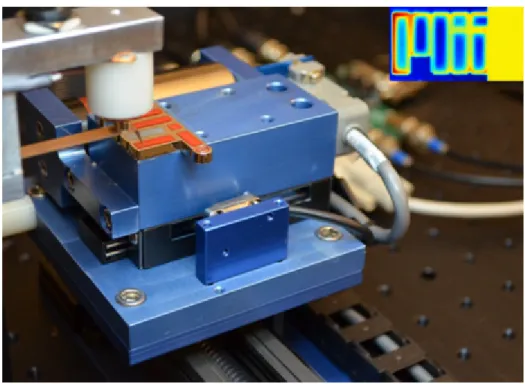
We have tested the effectiveness of the reticle assist device in compensating the reticle inertial loads. The experimental setup is shown in Figure 1-18. The setup consists of a reticle mounted on a stationary vacuum clamp. Coils are attached to the top and bottom surfaces of the reticle. These coils are used with magnet arrays to generate forces acting on the reticle’s center of gravity. This allows us to simulate the reticle inertial loads using a stationary setup. The experimental setup has capacitive displacement sensors which monitor the location of the reticle and the assist device’s clamp relative to the base plate. The setup also has the vacuum and pressurized air
0 20 40 60 0 10 20 30 40 50 60 F R [N] F [N] Experimental Ideal
Figure 1-17: Assist device’s resulting compensation force versus the inertial load plotted for 10 consecutive cycles.
lines used with the clamps and the pneumatic bellow. We used the coils to generate a 60-N simulated inertial load profile and monitored the reticle’s displacement with and without using the reticle assist device. As can be seen in Fig. 1-19, the reticle assist device is very effective at preventing reticle-slip. Without an assist device, the reticle moves as the clamps deform elastically by about 1 µm. However, some amount of this deformation is not reversed, and the reticle slips by more than 100 nm after 10 acceleration cycles. However, with this reticle assist device, the clamps elastically deform by only 20 nm and the reticle does not slip even after 10 cycles. The experimental procedures and results are presented in Chapter 6, Section 6.2.
Figure 1-18: Picture of the experimental setup used for testing and development of the reticle assist device (RAD).
0.02 0 2 -0.02 0 -0.2 0 0.2 m ] no RAD with RAD 0.3 0.35 0.4 -0.6 -0.4 R e ti c le M o ti o n [μ m 0 0.5 1 1.5 2 -1T -0.8 Time [s]
Figure 1-19: The reticle motion relative to the stage as a result of a 60-N simulated inertial load profile with and without using our reticle assist device (RAD).
Chapter 2
Reticle Slip Problem and
Conceptual Solutions
In this chapter, we describe the reticle slip problem, present promising conceptual designs, and conclude by selecting the most suitable concept for designing the reticle assist device.
2.1
Reticle Slip Problem
A simplified diagram of a lithography scanner is shown in Figure 2-1. The scanner ex-poses the wafer by sweeping an exposure slit across the reticle. To map the reticle to a whole die on the wafer, the scanner moves the wafer and the reticle relative to each other with nanometer-level coordination of motion. The reticle stage holds the reticle using a vacuum clamp and moves it in the X-direction. The reticle stage’s linear mo-tion path consists of acceleramo-tion at the ends of each scan and constant-speed momo-tion in the middle of the scan. Figure 2-1 shows the reticle stage accelerating (aR) in the
X-direction, which results in an inertial force (FI) being in the negative x-direction.
A large inertial force can cause reticle slip and displace the reticle to the location shown using the dotted box. As the inertial force approaches the clamp’s force limit, significant pre-sliding slip starts to occur. Sliding slip can occur if the inertial force exceeds the clamp’s limit. For more perspective on lithography machines, Butler [14]
reticle clamp reticle stage X Z FI g optical column wafer aR stator wafer stage wafer aW
Figure 2-1: Simplified diagram of a lithography scanner.
provides a detailed description of the operation and position control of lithography scanners.
To avoid deforming the reticle, a vacuum clamp is used for holding it. The reticle size and shape is set by the industry standard. Therefore, the available vacuum clamp area is limited. Given the restriction on the allowable materials, the coefficient of friction at the clamp’s interface cannot be increased. As a result, a limit is set on the clamp’s maximum force carrying capacity. The reticle inertial force for the next generation scanners can approach or even exceed this limit. Consequently, reticle slip can be a major error source for the next generation scanners.
2.2
Application Requirements
One method to address the slip problem is to use a reticle assist device, which fully or partially carries the reticle’s inertial force by exerting a force on the reticle’s edge. The reticle assist device will be placed on the reticle stage and will be interacting with the reticle. Being so close to the heart of the lithography process, the assist device must satisfy several application requirements in order to avoid disturbing the
lithography process and degrading the scanner’s performance. The main requirements and guidelines for designing the reticle assist device are as the following:
1. Low added mass from the assist device is required to ensure good reticle stage dynamics. A total mass budget of 0.3 kg, 0.15 kg per side, is provided to us as an approximate guideline.
2. Lifetime of at least 7 years with continuous operation is expected. During the assist device’s life time, 1 million reticle exchanges and 500 million pushing cycles can occur.
3. High reliability is required. The scanners are designed with high reliability for operation with minimum down time.
4. Output force must counteract the reticle’s inertial force during the acceleration interval, such that the remaining net force on the reticle is less than 30% of the inertial force. The device must be cable of exerting forces up to 50 N.
5. No disturbance on the reticle should cause more than 1-nm reticle motion or pattern deformation during the exposure interval. A compressive force of ap-proximately 2 N can cause as much as 1 nm deformation within the reticle’s patterned area.
6. Fast transient time of 1 ms between when the acceleration cycle is complete and when the assist device creates no disturbance on the reticle is required.
7. Pusher vibration modes must be above 1 kHz to avoid negatively impacting the stage dynamics and motion control.
8. Reticle size variation of ±0.4 mm and any additional reticle positioning toler-ance should be tolerated by the assist device. As a result, the assist device is required to have a coarse adjustment range of 1 mm.
9. No damage to reticle is allowed. The contact stresses induced within the reticle must be limited to avoid damage.
10. No large impact forces can be tolerated. Large impact forces can damage the reticle or cause slip. The reticle-tip contact must be controlled to avoid impact. 11. Cables or lines connecting to the assist device can disturb the stage and must
be minimized.
12. Illumination light cone cannot be blocked by the assist device.
13. Contaminating the scanner’s enclosure by particle generation or leakage is not allowed.
2.3
Conceptual Designs
We considered several different actuation technologies for designing a reticle assist de-vice (RAD). In the following subsections, we describe the most promising conceptual designs.
2.3.1
Piezoelectric Concept
A simplified diagram of the piezoelectric RAD concept is shown in Figure 2-2. The device uses a piezoelectric actuator to push on the reticle. The piezoelectric actuator has a limited range (order of 10 µm), and thus requires a coarse actuation mechanism to adjust the piezo’s position according to the variations in the reticle size and posi-tion. The coarse approach mechanism consists of a pneumatic bellow and a vacuum clamp. The coarse adjustment is performed by preloading the piezo against the ret-icle, extending the piezo by the desired gap size, and activating the vacuum clamp. The bellow and the vacuum clamp can be operated using on-off pneumatic-valves. It is possible to design a pneumatic circuit logic such that the bellow and the device’s clamp are actuated from the reticle clamp’s vacuum supply, but with fixed delays. In this way, no additional vacuum lines need to be brought onto the reticle stage. The piezoelectric device is solid-state, meaning that it has no moving parts. It has very fast dynamics and its motion can be controlled with high precision. The piezoelec-tric assist device also has the advantage of being light. For example, a commercially
stator core coil magnet t pushing element armature core
stator core & coarse stage coil pneumatic bellow vacuum clamp magnetostrictive element Clamp valve bellow valve Clamp valve coarse stage pneumatic bellow vacuum clamp piezoelectric element bellow valve p clamp valve normal piezo stator shear piezo mover
Figure 2-2: Conceptual design of a piezoelectric reticle assist device.
available piezo stack actuator weighing less than 20 g has a range of 15 µm and can exert a pushing force as high as 100 N [66].
2.3.2
Magnetostrictive Concept
The magnetostrictive assist device concept is similar to the piezoelectric concept, which was described in Section 2.3.1, except that the piezoelectric element is re-placed by a magnetostrictive element and its associated driving coils. A simplified diagram of the magnetostrictive RAD concept is shown in Figure 2-3. The device uses a magnetostrictive actuator to push on the reticle. The actuator consists of a magnetostrictive element with a coil wrapped around it. Energizing the coil creates a magnetic field through the element, which extends its length. Given the actua-tor’s limited range, it is used with a coarse adjustment mechanism. Compared to the piezoelectric assist device, the magnetostrictive assist device has two main disad-vantages: it is heavier and less efficient. First the copper coils and magnetic circuit add to the actuator’s mass. Also, the coil resistive power loss dissipates energy even when holding a constant extension. The heat from the coils can result in thermal expansion of the magnetostrictive actuator and other stage components. However, the magnetostrictive actuator has two advantages. It requires a current source, and thus can potentially be directly driven in series with the reticle stage’s motor coil currents. Also, the magnetostrictive element does not have a stack construction and
stator core coil magnet t pushing element armature core
stator core & coarse stage coil pneumatic bellow vacuum clamp magnetostrictive element Clamp valve bellow valve Clamp valve coarse stage pneumatic bellow vacuum clamp piezoelectric element bellow valve p clamp valve normal piezo stator shear piezo mover
Figure 2-3: Conceptual design of a magnetostrictive reticle assist device.
is mechanically stronger, whereas piezoelectric elements can suffer brittle fracture. For a pushing force of 75 N, an actuation range of 10 µm, and 1.6 W maximum dissipation, the expected mass of the assist device’s magnetostrictive element, coils, and magnetic cores is estimated to be 270 g. This mass estimate does not include the coarse adjustment mechanism.
2.3.3
Electromagnetic Concept
Another option is a moving iron actuator similar to the flux-steering actuator designed by [50]. A simplified diagram of this assist device concept is shown in Figure 2-4. The electromagnetic actuator uses a permanent magnet to create a bias magnetic field in the air gaps on the two sides of the armature. The coils are used to steer the flux towards one side of the armature and create a net force in that direction. The permanent magnet makes the actuator more efficient because with a bias a larger net force can be generated for a given change in the coil current. The main disadvantage of the electromagnetic actuator is that it is open-loop unstable and requires closed-loop control with displacement sensor feedback. The key advantage of the concept is that it can be designed to have a range of 1 mm, and thus can be used without a coarse approach mechanism. For a pushing force of 75 N, an actuation range of 1 mm, and 1.2 W maximum power dissipation, the expected mass of the assist device’s
stator core coil magnet t pushing element armature core
stator core & coarse stage coil pneumatic bellow vacuum clamp magnetostrictive element Clamp valve bellow valve Clamp valve coarse stage pneumatic bellow vacuum clamp magnetostrictive element bellow valve p clamp valve normal piezo stator shear piezo mover
Figure 2-4: Conceptual design of an electromagnetic reticle assist device, inspired by actuator design of Lu [50].
coils and magnetic core is estimated to be 220 g. The mass estimate does not include the supporting structure.
2.3.4
Piezo Stepping Motor Concept
A simplified diagram of a piezo stepper assist device concept is shown in Figure 2-5. Piezo steppers, such as the Physik Instrumente’s PiezoWalk R linear motors, are commercially available. The mover is moved forward by the shear piezos and is clamped using the normal piezos. A set of two legs can work together to step the mover forward or backward. We can use the stepping actuation for coarse adjustment and use the shear piezos, with the normal piezos in the clamped state, for fine actuation and exerting the pushing forces on the reticle. Disadvantages of the piezo steppers are their high cost and the possibility of wear as a result of the repeated clamping action and the shear loading of the normal piezos. The Physik Instrumente N-111.20 PiezoWalk R has a range of 10 mm, a maximum force of 50 N, and weight of 245 g. The piezoelectric motor is expected to dissipate little energy.
2.3.5
Pneumatic/Hydraulic Bellow Concept
We have also considered using pneumatic or hydraulic bellows for creating the pushing forces. The bellows are very light. However, it is very difficult to control their motion
stator core coil magnet t pushing element armature core
stator core & coarse stage coil pneumatic bellow vacuum clamp magnetostrictive element Clamp valve bellow valve Clamp valve coarse stage pneumatic bellow vacuum clamp piezoelectric element bellow valve p clamp valve normal piezo stator shear piezo mover
Figure 2-5: Piezo stepping motor concept.
and output force with sufficient speed and precision. To make the bellows compact enough, they would also require a relatively high actuating pressure. For example, with a surface area of A = 1 cm2, a pressure difference of P = 50 × 104 P a ' 5 Atm is
required to create a pushing force of F = P × A = 50 N This introduces a significant chance of leakage and failure over the life time of the scanner.
2.4
Concept Selection
We have selected the piezoelectric concept for designing the reticle assist device. The piezoelectric assist device uses solid-state actuation and has no moving parts, except for micrometer-level elastic extension of the piezo. The main advantages of the piezoelectric assist device are as the following:
• Low Mass: the piezo actuator mass can be less than 20 g. The total mass including the coarse approach stage can be less than 100 g.
• Long Life Time: the piezo device has no moving parts and no fundamental wear mechanism.
• High Reliability: The piezo device is simple and does not have many failure modes. In its failed state, the device is a solid piece which does not affect the scanner’s operation.
• Excellent Dynamics: the assist device can be designed to have no low-frequency vibration modes; first mode can be in excess of 1 kHz.
• Open-Loop Stable: the piezo is open-loop stable and can be operated without a sensor and a closed-loop controller.
• High Control Bandwidth: the piezo’s motion and force can be controlled at a high bandwidth.
• High Control Resolution: the piezo’s motion can be controlled with high reso-lution.
Given these advantages, a piezoelectric assist device can provide a practical so-lution to the reticle slip problem. In the following chapter, we present the detailed design of an assist device based on the piezoelectric conceptual design.


![Figure 1-8: ASML’s force-limiting pushing tip mechanism by Zordan. Figure is taken from US Patent Application 13/022,247 [86].](https://thumb-eu.123doks.com/thumbv2/123doknet/14678301.558608/36.918.226.695.106.353/figure-limiting-pushing-mechanism-zordan-figure-patent-application.webp)
![Figure 1-9: ASML’s solid-state reticle assist device idea by Amin-Shahidi. Figure is taken from US Patent Application 13/281,718 [4].](https://thumb-eu.123doks.com/thumbv2/123doknet/14678301.558608/37.918.149.769.106.479/figure-reticle-assist-device-shahidi-figure-patent-application.webp)

![Figure 2-4: Conceptual design of an electromagnetic reticle assist device, inspired by actuator design of Lu [50].](https://thumb-eu.123doks.com/thumbv2/123doknet/14678301.558608/57.918.230.693.110.355/figure-conceptual-design-electromagnetic-reticle-assist-inspired-actuator.webp)


