Design of a Quadruped Walking Robot for Social Interaction by
Christopher John Morse B.S. Mechanical Engineering, 1997
Northeastern University
Submitted to the Department of Mechanical Engineering in partial fulfillment of the requirements for the degree of
Master of Science in Mechanical Engineering at the
MASSACHUSETTS INSTITUTE OF TECHNOLOGY February 2001
2001 Massachusetts Institute of Technology, All rights reserved
Signature of Author ...
.-Department of Mechanical Engineering February 2, 2001
C ertified by ...
Gill A. Pratt Assistant Professor of Electrical Engineering and Computer Science, MIT Thesis Supervisor
C ertified by ...
..--- tresto maiicu Adjunct Professor of Mechanical Engineering, MIT Thesis Supervisor
Certified by ... ... . ...
Rodney A. Brooks Professor of Electrical Engineering and Computer Science, MIT Thesis Supervisor
Accepted by ... -- AR
KER
Ain SoninChairman, Departmental Committee on Graduate Students
MASSACHUSETTS INSTITUTE
Design of a Quadruped Walking Robot for Social Interaction
by
Christopher John Morse
Submitted to the Department of Mechanical Engineering on January 19, 2001 in partial fulfillment of the requirements for the degree of Master of Science in
Mechanical Engineering
Abstract
This thesis describes the design of Coco, a mobile robot for the study of social behaviors in machines. Coco acts as a platform for research on the full range of problems involved in the development of social machines', including vision and auditory processing, computational synthesis of affective behaviors2, and motor control. In order to provide
maximum benefit to these research efforts, the goals of the design focused on maximizing the sensory input and expressive output available to the computer algorithms controlling the robot. The result is a static walking quadruped modeled on the morphology of a gorilla that stands approximately 0.5m tall and weighs 10.2kg. Coco has ten degrees of freedom in the limbs for walking and gesture. There are an additional five degrees of freedom in a vision head consisting of one narrow-angle and two wide-angle cameras. Servomotors receiving low-level PID control from an on-board DSP system actuate Coco's joints. Joint trajectories are transmitted from off-board computers via a serial link. Members of the Coco Team have successfully implemented behaviors such as orienting to and approaching both visual and auditory stimulus.
Thesis Supervisor: Gill A. Pratt
Title: Assistant Professor of Electrical Engineering and Computer Science Thesis Supervisor: Ernesto Blanco
Title: Adjunct Professor of Mechanical Engineering, MIT Thesis Supervisor: Rodney A. Brooks
Acknowledgments
This robot could not have been built without the efforts of the entire Coco Team: Charles Kemp, Naoki Sadakuni, Eduardo Torres-Jara, and Juan Velasquez. A special thanks to Naoki for performing the Creature Library simulations and to Charlie for spearheading the effort to analyze the head configuration. All the members of the Humanoid Robotics Group and the Leg Lab have provided a helping hand at one time or another that is greatly appreciated. Pete Dilworth, Ben Krupp, Dan Paluska, Jerry Pratt, and Dave Robinson all had their own robots to build and theses to write but were always available to provide great advice no matter how crazy the idea. Aaron Edsinger, Cynthia Breazeal, and Brian Scassellati provided experienced insights into the intricacies of cameras, and other robot mysteries.
Gill Pratt and Rod Brooks have been outstanding advisors from the beginning. Thank you so much for creating such a fun place to work and learn in. I also thank you for your patience in dealing with a student working in two labs at once.
Even when faced with my lousy formatting and last minute requests Max Berniker, Greg Huang, Eva Greger, Charlie, and Jerry all provided outstanding comments while proofreading this document.
Thanks to Eva whose love and support has made this effort so much easier. I can't imagine doing this without you. I love you. A special thanks to all my family and friends for putting up with my neglect while I've been in school but then always being right there when I need you. Thanks to Pete for setting me on this road in the first place. This work was funded by Yamaha Motor Corporation.
Contents
Chapter 1 Introduction ... 11
1.1 Thesis Goal... 11
1.2 Sum m ary of Thesis ... 12
Chapter 2 Concept D evelopm ent ... 13
2.1 Brief Overview ... 13
2.2 Design inspiration ... 15
2.2.1 Body ... 15
2.2.2 H ead ... 18
Chapter 3 Calculations and Sim ulation ... 22
Chapter 4 Hardw are Design ... 27
4.1 Shoulders... 27
4.2 Arm s ... 32
4.3 H ips and Legs... 33
4.4 H ead ... 36 4.5 Body ... 42 4.6 Electronics... 44 Chapter 5 Conclusions ... 46 5.1 Review of Thesis...46 5.2 Future W ork ... 47 5.3 Sum m ary ... 48
Appendix A Hum an Standard Anatom ical Position ... 50
Appendix B Suppliers ... 51
Appendix C Stock Parts ... 52
List of Figures
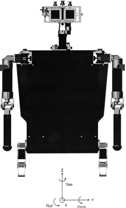
Figure 2-1: Coco is a ten degree of freedom quadruped walking robot with a five degree of freedom vision head... 13 Figure 2-2: The standard anatomical position defined for Coco. All geometric references
are m ade to this orientation of the robot ... 14 Figure 2-3: The polygon of support for statically stable walkers has vertices at the points
where the limbs touch the ground. This figure shows the transition from triple support to quad support as the outstretched right front limb (gray dashed circle) touches down. For slow static walking, the center of gravity must always remain inside the polygon . ... . . 16 Figure 2-4: Replicas of gorilla skeletons that show the relative proportions of a gorilla's
body (Reprinted with permission from Skulls Unlimited Int.) ... 16 Figure 2-5: Stick figure drawing of Coco's body configuration. The hips, knees and
elbows are simple one degree-of -freedom joints. The shoulder (dashed circle) has two degrees of freedom shown as two one degree-of-freedom joints with a small o ffset... 17 Figure 2-6: The human cervical spine and skull. Each vertebra acts as a 3 degree of
freedom joint with limited range of motion. Taken together, the joints of the c-spine provide 21 degrees of freedom but the limited range of motion allow them to be represented by 6 degrees of freedom ... 18 Figure 2-7: Simplified representation of how a lens focuses an image on the camera's
fo cal p lan e. ... 2 0 Figure 2-8: An object of unknown depth is projected onto the focal plane (A). If the camera is rotated through its optical center the object can be easily centered in the field of view (B). If the camera is rotated through any other point, the object cannot be centered without depth information (C). ... 20 Figure 2-9: A stick figure diagram of Coco's head configuration. Two cameras are
coupled to rotate in pitch and yaw about their optical center. A third camera shares the pitch axis. Arrow denote axes of rotation... 21 Figure 3-1: Worst case joint loading scenarios. Coco may experience the loadings shown though not necessarily in the manner shown. The estimation of maximum dynamic torque is based on the assumption that no joint will be more than ±45' from vertical during w alking... 23 Figure 3-2: Output from the Creature Library showing the torque in Coco's joint throughout the walking cycle. Axis labels were not available so various torque values are noted on the plots. ... 24 Figure 4-1: Coco's shoulder design uses a differential to allow both motors to mount vertically inside the body, lowering the center of gravity and allowing both motors to share th e load ... . . 27 Figure 4-2: Exploded view of the shoulder... 28 Figure 4-3: Cross section of Coco's shoulder output assembly showing the gears of the
Figure 4-4: Coco with its original shoulder. With the degrees of freedom oriented in roll and pitch the arms can be oriented to hug and perform a realistic chest beating b e h a v io r... 3 2 Figure 4-5: The original shoulder used the same differential arrangement as it's successor but the motors are perpendicular to the differential's input axis... 32 Figure 4-6: Coco's arm. The elbow motor is housed in the upper arm and drives the
elbow via a set of bevel gears. The forearm is hollow and has a threaded end to accept various hand com ponents... 33 Figure 4-7: Exploded view of Coco's hip. The hip motor (1) turns the inner leg assembly
via a timing belt. The knee motor mounts inside the output capstan (9) and actuates the knee via a timing belt in the thigh (not shown) ... 34 Figure 4-8: The leg bolts to the face of the hip capstan. The knee motor drives the knee
via a timing belt that runs down the thigh... 35 Figure 4-9: Coco's leg is comprised of a pair of plates (2) that can slide relative to
another pair (6&9) providing adjustment for the timing belt running from the knee motor at the hip to the knee joint. The foot (5) is a single aluminum part...36 Figure 4-10: Original and redesigned camera mounts. The original mounting frame (A)
used a CFRP plate with two small aluminum studs bonded on the surface to mount the yaw shaft. The minimal surface was prone to peel failure so the mount was redone with negligible weight gain as a single aluminum part (B)... 37 Figure 4-11: Head roll frame shown with its assembly jig. The locating pins (4) and
shaft (1) fix the assembly while the epoxy cures so that all critical geometry (IE the pitch axis mount) is properly positioned. The pitch frame used a similar jig to locate its critical geom etry... . 38 Figure 4-12: The pitch frame is a CFRP beam that employs ABS plastic inserts to mount
the pitch and yaw axes as well as the yaw motor mount (2)... 39 Figure 4-13: Head mount (8) , neck (7) and yaw frame (3). The neck is a tube that holds
the yaw motor and has bosses to mount the pitch capstan (6), pitch limit stop (11) , and shoulder screws (10). The yaw frame clamps to the yaw motor output (4) and mounts the roll motor (12), and roll axis bearings (1). ... 40 Figure 4-14: How a cable is supported on the capstan can have a dramatic effect on its life. An unsupported cable (B) cycles in and out of compression (A) as is winds on and off the capstan. If properly cradled (C), the crushing effect is minimized and life is extended. When the capstan cannot be designed to properly cradle the cable, close flanges (D) can be used to partially support the cable (The figure in D shows a capstan w ith tw o turns of cable on it). ... 42 Figure 4-15: Two views of Coco's CFRP body chassis. It is molded as a single part and has cutouts for the arms, legs, and head as well as bolt holes to directly mount the various com ponents... . 43 Figure 4-16: A trimming from the outer edge of the body chassis is saved and fixed inside the mold. When the back panel is laid-up and cured, it has lip that matches the body thickness so a nearly perfect lid is created. ... 43 Figure 4-17: Five MAX2000 3-axis motor controllers provide PID motor control. A tail
supplies power and serial communications with the controllers...45 Figure A-1. Standard Anatomical Position of a human ... 50
List of Tables
Table 3.3.1: Gear ratio selections for each joint of the body and the resulting joint performance data. (*The shoulder uses a differential arrangement which allows each axis to combine the output of two motors.) ... 25 Table 3.3.2: Torque requirements, gear ratio selections and resulting output capabilities and m ass of the head m otors. ... 25 Table B .1: L ist of Suppliers ... 51
Chapter 1
Introduction
1.1
Thesis Goal
The goal of this research effort is to develop a mobile robotic platform with multiple sensing capabilities for the study of social interaction between humans and machines. The robot, named Coco in large part because of its apelike form, will need to sense, explore, and interact with its environment. The main elements in the design are as follows:
" Recognizable and approachable form. A social robot should inherently inspire social behavior in humans. As humans, we interact with our environment based on our experience. Since social machines are few, we generally reserve social behavior for animals and other humans. To bridge this gap, the robot should be biomimetic, i.e. it should look less like a car and more like a pet.
" Small and light. The robot should be approachable by children as well as adults. A robot that is markedly smaller than its human caregiver is more likely to be perceived as non-threatening.
" Expressive. The robot should have a large repertoire of gestures and postures to facilitate the synthesis of emotional displays
" Complement vision processing. Visual input will be a major part of the complete robotic system. Any inherent intelligence in the mechanical system that simplifies the processing of camera information will result in faster, and more useful, responses.
" Robustness and ease of serviceability. Since the mechanical system is only a part of the larger effort to create a social robot whose end goal is to behave as a continuously running, "living-breathing robot", low mean time between failure and ease of assembly / disassembly are important.
* Accommodating to future changes. Coco's role as a research robot means that changes and additions are likely. The design should allow for upgrades and modifications.
1.2
Summary of Thesis
This thesis is organized as follows:
Chapter 2 describes the development of the robot's main attributes
Chapter 3 describes the calculations and simulations that defined the robot's power requirements
Chapter 4 describes the hardware design and selection Chapter 5 conclusions and future work
Chapter 2
Concept Development
2.1
Brief Overview
Coco (Figure 2-1) is a quadrupedal walking robot loosely modeled on the morphology of a Gorilla. The name Coco arises partly in homage to Koko, the famous Gorilla that has learned American Sign Language as part of an ongoing interspecies communication project3. Additionally, Coco is a repetition of the first two letters of cognitive which is also the root behind Cog4, Coco's sibling in the Humanoid Robotics Group. Mechanically, Coco is a ten degree of freedom walker with a five degree of freedom vision head. Coco weighs 10.2kg and stands approximately 0.48m tall. Brushed DC servomotors using digital encoder feedback actuate the robot. Low-level PID motor control is handled on board by a DSP in communication with off-board computers that process sensor data and supply high-level trajectory commands. Power is also supplied from off-board.
In order to describe the robot further, a standard orientation is needed to provide a basis for navigation and reference to parts of the anatomy. In human anatomy, this is called the standard anatomical position and is shown in appendix A. The standard anatomical position for Coco is defined in Figure 2-2 below. All references made to the robot are from this orientation.
z
Yaw
( Y
Roll X Pitch
WI
Figure 2-2: The standard anatomical position defined for Coco. All geometric references are made to this orientation of the robot
2.2
Design inspiration
2.2.1 BodyAmong the myriad biological forms capable of serving as a model, the Coco Team' chose a gorilla. Gorillas posses several traits that map closely to our design goals. The most attractive trait of gorilla morphology is their dual-purpose front limbs. Gorillas use their front limbs for gesture and manipulation as humans do, but their primary mode of locomotion is quadrupedal.
The statically stable nature of slow quadrupedal locomotion makes it a far simpler task for a robot than bipedal locomotion. Statically stable locomotion as described by McGee and Frank5 and later Raibert6 dictates that the projection of the robot's center of gravity on the ground must remain inside the polygon of support formed by the three (or more) points in contact with the ground (Figure 2-3). It follows that the center of gravity must remain relatively centered over these points throughout the gait cycle to insure stability. As a limb is lifted and moved away from the body to make a stride, the center of mass necessarily shifts toward the edge of the polygon of support. Heavy limbs can reduce the length of stride by causing the robot to fall onto its swing leg. Spiders, horses, cheetahs, etc all have very centralized masses supported by thin, light limbs that enable either great stability or long stride length.
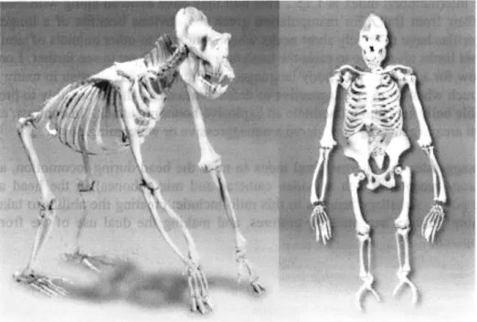
As seen in Figure 2-4, a Gorilla's front limbs are slightly longer than its hind limbs. The ratio of front to rear limb length is referred to as the intermembral index. For gorillas, the average intermembral index is 1.157. This trait may have evolved along with their ability to use their front limbs for manipulation given the obvious benefits of a longer reach. Since gorillas have relatively short necks when compared to other animals of similar size, long front limbs also serve to raise the head thus allowing them to see farther. Long limbs also allow for a great deal of body language. A common behavior seen in many animals is to crouch when taking an aggressive or defensive stance. This is possibly to protect the vulnerable belly area and to facilitate an explosive bounding attack. In contrast, exposing the chest area is generally considered a nonaggressive or welcoming posture.
Coco exaggerates the intermembral index to raise the head during locomotion, allowing the sensory receptors (such as video cameras and microphones) in the head a higher vantage point. Ancillary benefits to this ratio include: creating the ability to take a very welcoming posture, accentuating gestures, and making the dual use of the front limbs more apparent.
-4
Figure 2-3: The polygon of support for statically stable walkers has vertices at the points where the limbs touch the ground. This figure shows the transition from triple support to quad support as the outstretched right front limb (gray dashed circle) touches down. For slow static walking, the center of gravity must always
remain inside the polygon.
Figure 2-4: Replicas of gorilla skeletons that show the relative proportions of a gorilla's body (Reprinted with permission from Skulls Unlimited Int.8)
In keeping with the desire to make Coco approachable by people of nearly any age the robot's scale was chosen to be equivalent to a large cat or small dog; about 0.5m from head to tail and weighing 10-11kg. A larger, heavier robot would risk injuring itself or others while if it fell or hit something while gesturing. Since complex, multi-degree-of-freedom joints are generally more difficult to implement in small spaces, the robot only implements the major axes of motion necessary to enable the robot to walk and gesture and remain true to its biological inspiration. Feet and hands were eliminated since they involve some of the most complex mechanics of the body but are not required for quadrupedal locomotion. They are also small compared to the whole body so their absence does not markedly detract from the overall appearance. At the hip, the majority of motion is in flexion and extension. The other two axes of rotation provide negligible benefits to simple walking, and thus were eliminated. The shoulder must be used for pointing and gesturing as well as walking. A three-degree-of-freedom joint is desirable at the shoulder, but very complex to execute, so a two-degree-of-freedom joint, operating in yaw and pitch, was used. Knees and elbows in primates are essentially one degree of freedom and remain so on Coco. The result is ten degrees of freedom in the limbs. Figure 2-5 shows the joint configuration for Coco's body.
H ip Shoulder\
... Knee
Elbow
Figure 2-5: Stick figure drawing of Coco's body configuration. The hips, knees and elbows are simple one degree-of -freedom joints. The shoulder (dashed circle) has
two degrees of freedom shown as two one degree-of-freedom joints with a small offset.
2.2.2 Head
There are three major considerations in the design of a vision head for a mobile platform: (1) Maximizing the workspace available to the cameras, (2) placing the axes so that they help instead of hinder vision processing, and (3) aggressively minimizing weight. In the case of Coco there are the added considerations of the ability to produce gestures that suggest emotion and the approximation of animal morphology.
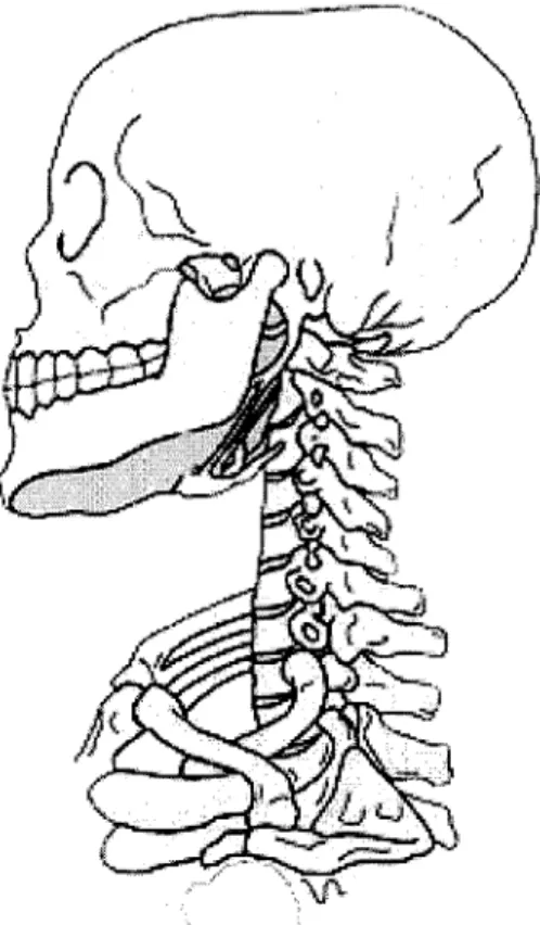
The human head and neck is an excellent example of the type of highly articulate vision platform that is desired for Coco. The seven stacked vertebrae of the cervical spine -each acting like a 3 degree-of-freedom ball-and-socket joint- give the human head roughly 21 degrees of freedom. Adding this to the two degrees of freedom in each eye" results in a total of 25 degrees of freedom in the workspace of the eyes. Unfortunately, this number would be nearly impossible to implement in a small mobile robot.
Figure 2-6: The human cervical spine and skull. Each vertebra acts as a 3 degree of freedom joint with limited range of motion. Taken together, the joints of the c-spine
provide 21 degrees of freedom but the limited range of motion allow them to be represented by 6 degrees of freedom.
It is possible, however, to reduce this number while still retaining much of the capabilities of a human. Although the individual vertebrae in the neck act as 3 degree-of-freedom ball-and-socket joints their range of motion is limited and the actuating musculature couples them together. Thus the neck can be approximated by a two-degree-of-freedom joint at the base of the neck and a three degree of freedom joint at the top with a linear slide between. The angular movements originating at the base of the neck are small, resulting in small length changes along the neck so it is also reasonable to neglect the linear slide. Although vergence (independent movement of the eyes on the yaw axis) plays a large role in some aspects of human vision processing, the majority of gross eye motion is conjunctive. This allows emulation of a pair of eyes with only two degrees of freedom. Thus it is possible to recreate most of the capabilities of the human vision platform with only seven degrees of freedom. Although manageable, seven is still a large number for a mobile robot, given the desire for low weight. Also, the two neck joints are multi-degree of freedom. As one adds axes to a joint the complexity increases greatly. Therefore, we reduced the neck axes from five to three giving Coco a total of five degrees of freedom for its vision system."'
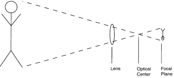
The location and orientation of the axes of the vision head play an important role in determining how well the entire vision system operates. The system must account for how its movements will affect what the cameras see. In an ideal camera the lens focuses a large image on the imaging plane by inverting it through a single point known as the optical center (Figure 2-7). As shown in Figure 2-8-A&B if the camera rotates around the optical center, the image that is projected will be rotated relative to the original image whereas rotation around any other point will cause both a translation and rotation. Unless the camera is rotated about the optical center, it is impossible to orient the camera to objects viewed on the optical plane without depth information as shown in Figure 2-8-C. Camera translation also changes the size of objects in view, which can confuse vision algorithms.
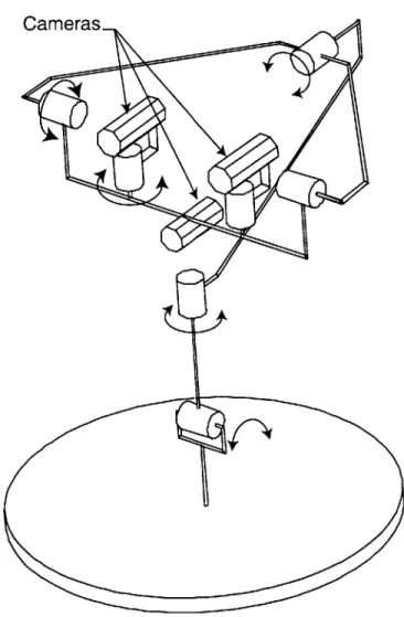
If it is impossible to locate the axis of rotation and the optical center, additional degrees of freedom can be used to create a virtual axis of rotation. The drawbacks to this solution are errors introduced by inaccuracies in positioning and the complexity of programming smooth coordinated movements by two actuators. Therefore, in Coco the optical center of the cameras played a key role in the design of the head. The main camera's yaw and pitch axes both intersect their optical center. A third camera used for detailed inspection of smaller areas shares the pitch axis with the two main cameras but its optical center is offset due to lack of space. A roll axis was also placed in plane with the optical center's of the main cameras to allow them to always remain parallel to the ground. In the neck, a second yaw axis was placed in line with the high detail camera's optical center. The final degree of freedom is a pitch axis at the base of the neck, which allows the robot to nod. The best overall description of this system is a double two-degree-of-freedom gimbal that
Charles Kemp, a fellow Coco group member familiar with vision processing, collaborated on the abstract head design and in particular
is wholly rotated configuration.
by on a pitch axis at its base. Figure 2-9 shows the final head
0O
7Q
Lens Optical Focal
Center Plane
Figure 2-7: Simplified representation of how a lens focuses an image on the camera's focal plane.
A - -Op t ca Cete p .- -' -- b B p C P p
Figure 2-8: An object of unknown depth is projected onto the focal plane (A). If the camera is rotated through its optical center the object can be easily centered in
the field of view (B). If the camera is rotated through any other point, the object cannot be centered without depth information (C).
Ce nter of Rotation
Cameras
Figure 2-9: A stick figure diagram of Coco's head configuration. Two cameras are coupled to rotate in pitch and yaw about their optical center. A third camera shares
the pitch axis. Arrow denote axes of rotation.
Coco's design balances expressiveness and biomorphism with mobility and low weight. The robot's long arms, contrasted with short legs, enable broad hand gestures and an open, friendly posture. The head configuration accommodates the needs of the vision system and maximizes the workspace while minimizing both weight and complexity. The result is a fifteen degree-of-freedom robot inspired by the morphology of gorillas.
Chapter 3
Calculations and Simulation
Designing a mobile robot is an iterative process. In order to calculate how much power each axis of the robot requires one must know how much it weighs and how fast it has to move. However, the weight is largely dependent on the size of the motor that is delivering the power. In the case of Coco, the maximum joint speed was determined by comparisons to humans. In human limbs, joint speeds are 6-13rad/s (1-2Hz)9 for slow to average walking. Using human speed data means that the overall speed of the robot will be scaled in proportion to the ratio of limb length between humans and the robot. This scaling fits the overall model for Coco as a slow, nonagressive being. In the head, the average joint speeds are 13-18rad/s (2-3Hz). Scaling does not play as big a role in the head since it is much closer to actual human proportions. As a starting point, the robot's total weight was estimated at 10kg.
The motor torque requirements were determined using the weight estimation and a set of worst-case joint loading scenarios (Figure 3-1) that resulted from examination of the expected modes of operation (IE walking, standing, sitting, crouching, etc). Each limb is assigned half of Coco's full weight to account for circumstances in which Coco is in triple support and load is evenly distributed front and back or Coco is in near double support as occurs in the transition to and from sitting. The estimation of maximum dynamic torque is based on the assumption that no joint will more than ±450 from vertical during walking. Coco's orientation in the two photo's in Figure 3-1 is not meant to represent an actual loading situation. It is, however, possible for Coco to endure equivalent loads to one or more joints at the same time.
The loadings described above represent the maximum or motor-stall torques that are likely to be seen by the robot. In walking and other normal situations the robot is not expected to bend it's limbs past ±450 from vertical with a nonzero motor velocity; thus, the expected maximum dynamic torque was decreased by 12 (Figure 3-1). The limbs will be operating at the maximum dynamic torque when they are the extremes of their range-of-motion. At these points the joint speed will be the lowest and will increase as the limb moves closer to vertical. To estimate power, the joint speed at maximum torque was estimated to be one tenth of the maximum joint speed of 13rad/s or 1.3rad/s. Using these estimations of torque and speed, the power requirements for the joints in the body were estimated to be between 2-14Watts. Equation 1 details this process for the shoulder's pitch axis.
Joint Max. Max. Dyn. Torque Torque (Nm) (Nm) Elbow 7.65 5.4 Shoulder yaw 11.22 7.9 Shoulder pitch 15.3 10.8 Hip 5.61 3.9 Knee 2.29 1.6
Figure 3-1: Worst case joint loading scenarios. Coco may experience the loadings shown though not necessarily in the manner shown. The estimation of maximum
dynamic torque is based on the assumption that no joint will be more than +450 from vertical during walking.
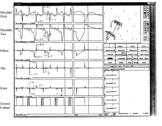
The static figures were tested using two separate dynamic simulations. Working Model(tm) is a dynamic modeler that imports geometry directly from the CAD system and allows the implementation of simple joint controllers. This system allows for improved analysis because it accounts for dynamic effects and weight distribution. The Creature Library is a dynamic simulator used by the MIT Leg Laboratory to develop walking robots. The emphasis in this system is on control. Since creatures are specified using simple geometric shapes the weight distribution is rudimentary, on par with the static calculations. Figure 3-2 shows joint torque plots output from the Creature library simulation"' that corroborates the static calculations.
MaxTorque = The maximum torque expected at the joint
MaxDyn Torque = The maximum torque expected during while moving MaxJointSpeed = The maximum speed of the joint
HighTorqueSpeed = The speed of the joint while supplying MaxDynTorque RqdPower = The estimate of the power needed by the joint
MaxDynTorque = F* MaxTorque = 2* 15.3Nm = 10.8Nm HighTorqueSpeed = Ma oint Speed = l3rad/s =1.3rad / s
10 10
RqdPower = MaxDynTorque* HighTorqueSpeed = 10.8Nm *1.3rad / s = 14W
4.4 4.14.s 16L V _ _ _ - I __. I NUN I5 _______ _____ 4. 142____ 11 7,_____ _______ Pro
'(3
ftuFL
Vilik
?
Xmi o sh 9" -20Iot -a 7AO-M -E 7~1U,.1._*Ikn IM2 111 vi., 1.1%9Figure 3-2: Output from the Creature Library showing the torque in Coco's joint throughout the walking cycle. Axis labels were not available so various torque
values are noted on the plots.
Based on the simulations and static calculations, we chose a 24V, Maxon, ReO25 brushed, DC motor, rated for 20W to actuate the limbs. This motor was chosen based on its package size and its ability to mount a gearhead strong enough to handle the high torques the robot must endure. Other, smaller motors had the ability to supply suitable
[1] Shoulder Pitch Shoulder Yaw Elbow Hip Knee Ground Contact
power but could not be easily mated to the proper transmission. The motor can supply 0.029Nm continuously with a stall torque of 0.24Nm. Output speed is limited to 5000-6000 RPM by the gearhead. Table 3.3.1 shows the configuration selected for each joint.
Joint Gear Gear Max.Speed Continuous Stall Torque Mass
ratio efficiency (RPM) Torque (Nm) (Nm) (g
Shoulder* 51:1 0.70 117 1.07 12.24 330
Elbow 86:1 0.70 70 1.81 20.64 330
Hip 120:1 0.70 50 2.78 31.68 330
Knee 111:1 0.70 54 2.33 26.64 330
Table 3.3.1: Gear ratio selections for each joint of the body and the resulting joint performance data. (*The shoulder uses a differential arrangement which allows
each axis to combine the output of two motors.)
The process for the design of the head is in marked contrast to the design of the legs. As previously mentioned, designing the legs was a continuously iterative process; since all ten degrees of freedom are dependent on each other there is no distinct starting point. The head was simpler to design since it is essentially a serial robot arm with a well-defined payload: the cameras. Starting at the most distal point with the known mass of the cameras, each degree of freedom could be independently designed using the preceding inertial characteristics.
Req'd Continuous Stall
Torque Gear Gear Max.Speed Torque Torque Mass
Joint (mNm) Ratio efficiency (RPM) (mNm) (mNm) (g)
Camera Yaw 50 41:1 0.73 146 99 269 48 Camera pitch 100 66:1 0.70 90 152 416 53 Roll 150 66:1 0.70 90 152 416 53 Neck Yaw 300 66:1 0.70 90 309 1039 140 Neck pitch 1000 231:1 0.49 25 866 2703 135
Table 3.3.2: Torque requirements, gear ratio selections and capabilities and mass of the head motors.
resulting output
The torque requirements and motor selection for each joint in the head are shown in Table 3.3.2. The yaw, pitch, and roll axes of the head all use MicroMo 1524 motors that can produce 9mNm at stall and 3.3mNm continuously. The neck yaw motor uses a MicroMo 2224 motor that provides 6.7miNm continuously and 22.5mNm at stall. The
at stall. Like the motors selected for the body, motor speeds are limited to approximately 6000RPM by the gearheads.
The power estimations lead to motor selections with a total mass of 3.7 kg. Adding to this the 0.15kg per degree-of-freedom weight of the motor control electronics resulted in approximately 6.0kg of mass necessary to power a 10.kg robot. The remaining 40% in the weight budget was available for additional transmission components and structure. Had these elements exceeded the weight budget the torque estimates would need to be revised and another iteration required.
Chapter 4
Hardware Design
4.1
Shoulders
Coco's head, long arms, broad shoulders, and the extra degree of freedom in the front limbs all tend to draw the center of gravity forward, making it harder to maintain the polygon of support. For this reason it was desirable to keep the shoulder motors inside the body and oriented parallel to the Z-axis of Coco's body. Coco's long arms also increase the expected torque. The need to supply high torque and a parallel motor configuration led to the selection of a differential drive system. Differential drives couple the two degrees of freedom allowing the motors to be mounted together and it enables each motor to equally share the load applied to the joint. This configuration also simplifies wiring the motors since the motors are stationary and inside the body. Running wires around joints increases the chances of failure and entanglement. Figure 4-1 shows the shoulder assembly.
Y
x
Z
00
Figure 4-1: Coco's shoulder design uses a differential to allow both motors to mount vertically inside the body, lowering the center of gravity and allowing both motors
to share the load.
The differential consists of three bevel gears; the two drive gears face each other on the Z [yaw] axis and actuate the output gear, which is mounted on the Y [pitch] axis. When the drive gears rotate in the same direction they cause the output to rotate around the drive
output gear's axis. The drive gears are connected to the motors in an unusual manner. The motor that drives the upper (closest to the head) drive gear is mounted coaxially to the drive axis. A shaft passes through clearance holes in the lower drive gear and the output mount to connect them. The lower drive gear has a spur gear mounted to its hub. A large diameter, deep-groove radial bearing and a thrust bearing support this two-gear set. The lower drive gear motor is located parallel to the upper drive gear motor and mounts an equally sized spur gear for 1:1 torque transfer. The output gear is mounted using a post and clevis arrangement. The clevis pin is a thin tube made from heat-treated tool steel, which is necessary to provide clearance for the upper drive gear's drive shaft. The output shaft is mounted using angular contact bearings oriented back-to-back (Figure 4-3-4). See Figure 4-2 for an exploded view of the shoulder.
1 X 321 1 11 3 8 2---'- 6 7 5 3 4
No. Description No. Description
1 Motors 12 Lower differential drive gear
2 Motor mounts 13 Differential output gear
3 Shaftlo TM 14 Angular contact bearings
4 Spur gear 15 Output shaft
5 Radial bearing 16 Arm mount
6 Shoulder housing 17 Bearing retainer plate
7 Output mounting post 18 Output housing
8 Upper gear drive shaft 19 Output mounting tube
9 Radial bearing 20 Radial bearings
10 Thin deep groove bearing 21 Upper differential drive gear
11 Spur gear
The key design constraint in mounting the output shaft was the need to keep the arm as close as possible to the yaw axis of the shoulder. In humans, the shoulder is essentially a ball and socket joint so the midline of the arm is collinear to yaw rotation. A differential
arrangement precludes this orientation so the arm will necessarily be offset from its axis of rotation. A large offset would significantly diminish the natural look of the robot's gestures. The internal structure and transmission components as well as the output assembly affect the size of the offset. The size of the internal components and structure determine how close the yaw axis can come to the top-front corners of the robot's body and thus how close the arm can be to the yaw axis without interfering with the body. The output shaft must be rigidly mounted to insure proper meshing of the bevel gears. The size of this mounting must be kept small since it comes between the output gear and the arm. To minimize the space occupied by the bearing assembly, the output shaft is threaded %-28 UNC for a portion of its length and then transitions to a precision surface. The bearings fit over the precision surface and a locknut screws onto the threads to preload them. The arm mount is also threaded so that it can screw onto the output shaft behind the locknut. The arm mount locks using a setscrew that engages a flat on the output shaft (Figure 2-1-1). By combining the arm mount and the preloading mechanism the size of the shaft mounting assembly is minimized.
The differential gives unlimited range of motion to the pitch axis but allowing the arm to revolve multiple times could tangle and break wires running from the arm. A bar on the arm mount stops against the head of a cap screw holding the bearing retainer plate
allowing rotations of +93' and - 2240. The yaw axis is inside the body and so is limited
by the amount of the chassis that can be removed to provide clearance and the necessary presence of the output mount. These issues limit the yaw rotation to +400 and -900. The workspace of the arm creates by these two ranges of motion does allow Coco to interfere with itself. If the yaw axis is near +40' then it is possible for the arm to strike the body if the yaw axis has an angle greater than approximately -200. The robot can also strike the head in certain orientations. Providing hard stops to avoid these possibilities would significantly limit the arm's workspace. Therefore, software limit stops that are conditional based on the position of both axes are used to avoid collisions.
The differential's reliance on gears that are positioned by several different mating parts to transmit power raises the issue of backlash. Tolerance stack-ups can cause backlash greater what is required for proper operation. In Coco's current configuration backlash is not a large issue because the motors are controlled directly from encoder feedback on the motor shaft. Backlash in the joints affects the final position of the limb but in current walking and gesture algorithms the tolerance for position errors is quite large. The differential assembly adds approximately 3.60 of backlash to the system. The spur gears that transmit power from the motor to the lower differential drive gear are high precision and well mounted so the backlash is no more that 0.50. The gearheads in the servomotor contribute approximately 3.90 so the total backlash in the system is roughly 7.5-8.0'. This amount of backlash may become a problem if future configurations require more precise positioning of the limb. If, for instance, it becomes necessary to control the limb from a sensor at the output of the joint backlash would cause a dead spot that would
adversely affect the control system. In cases like this, shimming the gears in the differential to remove errors caused by the multiple mating parts could reduce the backlash. Since the differential only accounts for 50% of total, the possible reduction is only about 30-40%. The elbow joint also uses bevel gears to transmit power from the motor to the joint. In this case, there is only one part, aside from bearings and a precision shaft, responsible for locating the two gears so the backlash is only about 1.00.
4
2
114
7
5
8
9
10
12
No. Description No. Description
1 Threaded section of output shaft 8 Output housing 2 Bearing mount area of output shaft 9 Output mounting post
3 Bearing retainer plate 10 Thrust washer
4 Back-to-back bearing set 11 Radial bearing
5 Spacer 12 Lower differential drive gear
6 Output mounting tube 13 Differential output gear 7 Upper differential drive gear 14 Hex nut
Figure 4-3: Cross section of Coco's shoulder output assembly showing the gears of the differential, output shaft, and mounting post
The emphasis placed on minimizing space and weight lead to the breaking of a traditional rule in the design of mechanical transmission systems. The drive shafts are overconstrained. The output shaft from the motors is fully supported by internal bearings. In the case of the upper drive gear the connecting shaft should have a compliant coupling to account for misalignment. The driving spur gear for the lower drive gear can apply more radial force to the motor bearing than they can handle, so additional support is required. Ideally, the spur gear would have its own supports and the motor would be connected through a flexible coupling. In an overconstrained system the slightest misalignment can cause high loads on the bearings leading to premature failure. To combat misalignment, the mating parts were carefully toleranced for parallelism. Additionally, the motors were mounted to their drive shafts and allowed to "find" the best location by rotating the joints as the mounting screws were tightened. Provisions were made such that once the motors were located they could be permanently fixed with dowel pins.
This design maintains a low overall center of gravity for the robot. It also positions the axes of rotation very close to the outside corners of the robot, closely approximating a biological shoulder.
The design previously described is the second one implemented on Coco. The original design had the two degrees of freedom oriented in roll and pitch instead of yaw and pitch. This configuration was the result of a focus on the robot's walking characteristics and neglecting some of the needs for gesture. Figure 4-4 shows how the original design allowed Coco to make chest beating and hugging gestures as well as large lateral movements while walking. Unfortunately, with the axes oriented to provide roll and pitch rotation the arm is unable to point to arbitrary locations in the Y-Z plane. The arm can only move one-dimensionally along the Y or Z-axes. The inability of the robot to point to objects in front it was an unacceptable drawback to the original design.
The original and final shoulder designs share the same differential system but the orientation necessarily differs. In the final shoulder the motors are parallel to the differential's input axis which allows one motor to connect directly to the differential. The second motor is offset from the input axis so a spur gear transmits the power. In the original design (Figure 4-5) the motor's are perpendicular to the differential's input axis. In this case, both motors use bevel gears to transmit power to the differential.
Figure 4-4: Coco with its original shoulder. With the degrees of freedom oriented in roll and pitch the arms can be oriented to hug and
perform a realistic chest beating behavior. Figure 4-5: The original shoulder used the same differential arrangement as it's successor but the
motors are perpendicular to the differential's input axis.
4.2
Arms
As described earlier, the arms are mobile masses that can greatly shift the robot's center of mass during walking. To minimize weight, the structure of the arms primarily consists of carbon fiber reinforced polymer (CFRP) tubes. The elbow motor resides in the upper arm and actuates the elbow trough a set of bevel gears. At the top of the upper arm, an aluminum block provides an attachment point for the output of the shoulder. The mounting block (Figure 4-6-13) has a large cutout for the elbow motor's encoder. Four bolts pass through slots in the shoulder output to mount this block. The slots allow the arm to be rotated so, if necessary, the elbow axis can be adjusted relative to the body. A plastic spacer between the shoulder output and the arm block adds length to the arm. The current configuration has alOmm spacing but this is easily changed to accommodate future modifications. This block then bolts to a CFRP tube that surrounds the elbow motor.
At the elbow, a single aluminum part glued to the end of the CFRP tube both mounts the elbow motor and the bearings for the elbow axis. Creating the entire elbow knuckle out of a single part allows there to be a tight tolerance on the distance between the motor's mounting face and the elbow axis. This is a critical dimension that defines the spacing of the bevel gears that are used to transmit force perpendicularly from the motor to the elbow axis. The forearm mounts to the elbow axis via a clamp that straddles the output bevel gear and engages the output shaft. The range of motion of the elbow is +00 and -1350 , roughly equal to that of humans. In order to allow the forearm to bend this far it
was necessary to taper the forearm near the elbow. This was accomplished by gluing two narrow (6mm) CFRP shafts inside the forearm tube. These shafts mate to an aluminum boss that bolts onto the elbow clamp. The addition of these thin load-carrying members allows the forearm tube to be tapered to accommodate the elbow range of motion. At the end of the forearm tube, a threaded insert is glued inside the tube to allow different hand modules to be easily installed. Currently, Coco's hand is a simple rubber hemisphere. In the future, load cells, tactile sensors or grippers may be developed.
1
2
L
3
4
5
7
13
8
11_
10
9
No. Description No. Description
1 Spacer 8 Hand attachment
2 Elbow motor with encoder 9 CFRP tube
3 CFRP tube 10 Output mount
4 Elbow knuckle 11 Clamp
5 Angular contact bearing 12 Bevel Gears
6 Forearm mounting stud 13 Arm mounting boss
7 Thin CFRP tubes II
Figure 4-6: Coco's arm. The elbow motor is housed in the upper arm and drives the elbow via a set of bevel gears. The forearm is hollow and has a threaded end to
accept various hand components
4.3
Hips and Legs
Coco's short hind legs require the knee motors to reside inside the body due to the space constraints. Additionally, the cantilever nature of the hip joint coupled with high torques
transmitted from the leg require that it be well supported. One solution, which is often seen in robotics, is to fasten both motors to the body and pass the knee torque through the hip joint. This couples the movement of the two joints by requiring moves to be coordinated between the joints, slightly complicating the motor control algorithms.
10
8
8 76
0 0
No. Description No. Description
1 Hip Motor 7 Outer hip mounting plate
2 Shaftlo TM 8 Bearing
3 Hip motor capstan 9 Hip capstan
4 Bearing 10 Inner hip mounting plate
5 Hip output support frame 11 Knee motor
6 Knee motor capstan
Figure 4-7: Exploded view of Coco's hip. The hip motor (1) turns the inner leg
assembly via a timing belt. The knee motor mounts inside the output capstan (9) and actuates the knee via a timing belt in the thigh (not shown).
Coco's hip design decouples the hip and knee joints by rotating the knee motor with the hip and thigh. As shown in Figure 4-7, the knee motor is mounted coaxially to the hip inside a timing belt pulley. The thigh is mounted to the end of the pulley and a second timing belt connects the output of the knee motor to the knee joint with a 1:1 ratio. The leg-pulley-motor assembly is supported by large diameter, thin section bearings. Rotation is limited by a dowel pin protruding radially from the hip capstan. This pin interferes with dowel pins in the inner hip mounting plate (Figure 4-7-10) limiting rotation to +00 and -180".
From its offset position the hip motor drives the leg, pulley, motor assembly through a
reduction reduces the torque the hip motor's gearhead must endure which will increase the life of the joint. In this configuration, a cable drive would also have been a solution. However, the hip area provided more space for a thin and wide transmission, like timing belts, that can be made stronger by adding width, as opposed to cables that grow in both dimensions as strength is added. Additionally, the timing belt solution allowed placement of the tensioning mechanism away from the tight space of the leg assembly. The 2:1 reduction in the hip transmission required that the diameter of the drive pulley be as small as possible based on the minimum required diameter of the timing belts. The radial forces induced by the necessarily small and long driving pulley are higher than what the motor output shaft can handle. As with the shoulder drive shafts, an external, overconstraining support was added. The support bolts to the mounting face of the motor and connects to a bearing mount at the end of the driving pulley through a thin web. The flexibility of this web minimizes the force induced by the overconstraint. This system then bolts onto a pocket in the frame that supports the leg assembly. The pocket allows the timing belts to be properly tensioned and then bolted into place. This design combines compact packaging of the two motors, a shock-tolerant high-load-bearing system, and a torque increasing power transmission with the added benefit of decoupling the degrees of freedom.
0
Z Y
x
Figure 4-8: The leg bolts to the face of the hip capstan. The knee motor drives the knee via a timing belt that runs down the thigh.
Coco's thigh is made up of four plates that bolt to a central mounting block. One of the upper plates attaches to the hip capstan and the other supports the knee motor output shaft via a flange bushing. The lower pair of plates mount the shaft for the knee axis and have slotted holes for mounting to the central mounting block. This allows the knee's timing
aluminum part. Knee rotation is limited by the foot's (Figure 4-9-5) interference with the upper thigh plates (Figure 4-9-6&9). This occurs at ±1200.
No. Description 1 Knee shaft 2 Lower thigh plate
3 Bronze bushing 4 Knee capstan
5 Foot
6 Outside, upper thigh plate 7 Knee motor, capstan support
8 Central mounting block 9 Inside, upper thigh plate
Figure 4-9: Coco's leg is comprised of a pair of plates (2) that can slide relative to another pair (6&9) providing adjustment for the timing belt running from the knee
motor at the hip to the knee joint. The foot (5) is a single aluminum part.
4.4
Head
Excluding the camera and motor mounts, the frames that make up the structure of the head are all fabricated from 1.5mm thick laminated CFRP. The CFRP plates were used to create beams with great stiffness and low weight. The key advantages of the CFRP beam construction in the frames of the head are their great strength-to-weight ratio and the simple manufacturing method used. The flat CFRP laminate is cheap to manufacture and cut precisely using a water-jet. The camera roll and pitch frames are constructed using aluminum or ABS plastic inserts where shafts or screws are needed and balsa wood filler to provide additional shear area. The frames were assembled with the aid of locating jigs as shown in Figure 4-11 using high strength epoxy. An alternative to this method would be to laminate the CFRP skins, filler, and inserts together. This method is more costly due to the use of higher skilled labor, longer lead-time, and the necessity for deflashing and cleaning operations.
9 8 3 3 -5 3 2
A
BFigure 4-10: Original and redesigned camera mounts. The original mounting frame (A) used a CFRP plate with two small aluminum studs bonded on the surface to mount the yaw shaft. The minimal surface was prone to peel failure so the mount
was redone with negligible weight gain as a single aluminum part (B).
The yaw frame is of a simpler design. The two aluminum bosses that connect the frame to the yaw and roll axes have locating pins that simplify assembly and add to the shear strength of the bonded joint. The taper from the yaw mount to the roll mount simultaneously reduces material in the roll mount and adds lateral stiffness.
The original camera mounts were designed as CFRP plates bonded to aluminum studs (Figure 4-1OA). In practice, this quickly proved to be an inferior design due to the minimal bonding area and high peel forces induced by bending. Since the overall volume of the mounts is small it was feasible, on a weight basis, to machine them out of aluminum (Figure 4-10B). Therefore, we used this solution as it traded a small amount of weight for a large savings in robustness simplicity of manufacture.
The coupled camera yaw axes are actuated with a single motor. This motor mounts to a steel weldment (Figure 4-12-2) that, in turn, mounts to the pitch frame. A timing belt provides power transfer and encircles the driving capstan and the two driven capstans. The capstans were sized appropriately to engage the recommended number of belt teeth. The four mounting holes in the weldment are slotted to provide belt adjustment. Yaw motion is limited to ±45' by a plastic limit stop (Figure 4-12-6) mounted on the front of the pitch frame.
5
1 4
3
2
No. Description No. Description
1 Locating shaft 5 Assembly jig base
2 Aluminum insert 6 Roll cable terminator
3 CFRP plates 7 Roll capstan and bearing mount
4 Locating pin I
Figure 4-11: Head roll frame shown with its assembly jig. The locating pins (4) and shaft (1) fix the assembly while the epoxy cures so that all critical geometry (IE the
pitch axis mount) is properly positioned. The pitch frame used a similar jig to locate its critical geometry.
1
11
2
10
CC)
40
No. Description No. Description
1 Pitch drive capstan 7 Yaw motor
2 Yaw motor mounting weidment 8 Narrow angle camera & mount
3 Plastic insert 9 CFRP plates
4 Pitch capstan 10 Pitch motor
5 Cable tensioner 11 Yaw drive capstan
6 Yaw limit stop 12 Pitch motor mounts
Figure 4-12: The pitch frame is a CFRP beam that employs ABS plastic inserts to mount the pitch and yaw axes as well as the yaw motor mount (2).
2
14
31
12
4
0
11
7
10
8
9
No. Description No. Description
1 Roll bearing set 8 Head mount
2 Roll limit stops 9 Pitch axis bearing
3 CFRP plates 10 Shoulder screw
4 Yaw frame motor clamp 11 Pitch limit stop
5 Yaw limit stops 12 Roll motor
6 Pitch capstan 13 Roll motor clamps
7 Pitch frame 14 Roll driving capstan
Figure 4-13: Head mount (8) , neck (7) and yaw frame (3). The neck is a tube that holds the yaw motor and has bosses to mount the pitch capstan (6), pitch limit stop (11) , and shoulder screws (10). The yaw frame clamps to the yaw motor output (4)
Mounting the motors for camera pitch and roll was made easier through the use of off-the-shelf conduit clamps with an inside diameter that matched that of the motors. The camera pitch motor mounts to an aluminum boss in the back of the roll frame. A wire cable is used as the transmission medium to the pitch capstan. Pins in the pitch frame that interfere the roll frame limit the range of motion to ±400.
When designing cable drive systems, the recommended safety factor, relative to the breaking strength of the cable, is 10. Experience has shown that the safety factor can be reduced to 2 for research robots by designing capstans that conform to the best practices recommended by the manufacturer. This involves supporting the cable along its contour (Figure 4-14-C) instead of allowing it to deform, as it will when tensioned against a flat surface (Figure 4-14-B). If a cable winds onto a flat capstan it is compressed slightly by the reaction forces against the cable tension. This repeated compression of the cable weakens it over time. Even with proper support, the life of the cable will be reduced when operating with a safety factor of two but the duty cycles that the cable will see on
Coco push the trade-off between life and size/weight toward shorter life.
The practical application of this best practice is to use capstans that have a helix of proper cross-section cut into them. This insures that the cable is well supported as it takes the multiple turns necessary to generate the friction force needed to transmit the driving torque. In the camera pitch transmission, only the motor capstan could be grooved according to this best practice. Since the driven capstan is part of the camera pitch frame that is enclosed by the roll frame, and the desire for facial symmetry meant that both sides of the frame should be the same width, minimizing width was critical. In this case, the distance between the flanges of the capstan was designed so that they would support the sides of the cables to minimize deformation (Figure 4-14-D).
The transmission for the roll motor also used cables. In this case, both capstans had sufficient length to fully support the cable with a helical cut. The motor was mounted transverse to the roll axis on the yaw frame. Similar to the pitch limit stop, pins in the yaw frame interfere with the roll frame to limit roll motion to ±300 (Figure 4-13-2). The volume of the neck pitch frame is almost completely taken up by the yaw motor. A thin aluminum shell surrounds the motor to connect its mounting surface to the neck pitch axis. Bosses on the tube accept shoulder screws that run through bearings mounted in the head mounting plate to create the pitch axis. These bosses also mount a plastic limit stop (Figure 4-13-11) that constrains the pitch motion to ±700. The output shaft of the gear-motor for the yaw axis directly drives the yaw frame. A thrust bearing was added between the motor mount and the yaw frame to add stiffness to the head. A pair of tabs (Figure 4-13-5) on the tube interferes with a pin on the yaw frame to limit rotation to
B CD
Figure 4-14: How a cable is supported on the capstan can have a dramatic effect on its life. An unsupported cable (B) cycles in and out of compression (A) as is winds on and off the capstan. If properly cradled (C), the crushing effect is minimized and
life is extended. When the capstan cannot be designed to properly cradle the cable, close flanges (D) can be used to partially support the cable (The figure in D shows a
capstan with two turns of cable on it).
4.5
Body
Coco's body serves as mount for all of the individual extremities and all of the onboard electronics. The body chassis is also responsible for creating the rough overall appearance of a biological being. Although animals have decidedly flexible overall structures, Coco needs to have a stiff platform to mount the various components. A stiff structure will reduce the chances of breaking the electronic components mounted inside. Additionally, control algorithms are generally complicated by the introduction of unmodelled dynamics. Body flex would be difficult to model and could result in poor performance by causing unpredicted behavior in the motor control system.
There are several approaches and materials that could have suited all of these purposes. One method would have been to create a frame connecting the head, hips, and shoulders using aluminum or CFRP tubes. A cosmetic chassis could then be fitted around the structural components. Another option would have involved creating a welded monocoque frame out of sheet aluminum or steel.
For Coco's body we used a monocoque CFRP chassis. The benefits of CFRP are the smooth contoured shapes made possible by molding and exceptional stiffness afforded by the graphite reinforcement. Additionally, the ability to create the net shape of the robot from a single part results in a better appearance and simpler design and assembly. As shown in Figure 4-15 the body has tapered sides that give the appearance of broad primate shoulders which give way to a narrower waist. The sharp narrowing at the base