HAL Id: hal-01214530
https://hal.archives-ouvertes.fr/hal-01214530
Submitted on 10 Nov 2015
HAL is a multi-disciplinary open access
archive for the deposit and dissemination of
sci-entific research documents, whether they are
pub-lished or not. The documents may come from
teaching and research institutions in France or
abroad, or from public or private research centers.
L’archive ouverte pluridisciplinaire HAL, est
destinée au dépôt et à la diffusion de documents
scientifiques de niveau recherche, publiés ou non,
émanant des établissements d’enseignement et de
recherche français ou étrangers, des laboratoires
publics ou privés.
Identification of Burgers vectors along in In-doped
GaAs, by X-ray transmission topography and image
simulation.
N. Burle-Durbec, B. Pichaud, F. Minari, Alain Soyer, Yves Epelboin
To cite this version:
N. Burle-Durbec, B. Pichaud, F. Minari, Alain Soyer, Yves Epelboin. Identification of Burgers
vectors along in In-doped GaAs, by X-ray transmission topography and image simulation..
Jour-nal of Applied Crystallography, InternatioJour-nal Union of Crystallography, 1986, 19 (2), pp.140-141.
�10.1107/S0021889886089781�. �hal-01214530�
140
Short Communications
Contributions intended for publication under this heading should be expressly so marked; they should not exceed about 1000 words; they should be forwarded in the usual way to the appropriate Co-editor; they will be published as speedily as possible.
J. Appl. Cryst. (1986). 19, 140-141
Identification of Burgers vectors along (111) in In-doped GaAs, by X-ray transmission topography and
image simulation.
By N.
BURLE-DURBEC, B. PICHAUD and F. MINARI, Laboratoire de Physique Cristalline, Unit~ Associde au CNRS, Universitb Aix-Marseille I l l , rue H. Poincard, 13397 Marseille CEDEX 13, France and A. SOYER and Y. EPELBOIN, Laboratoire de Min&alogie et Cristallographie, Unit~ Associ~e au CNRS, Universitd Pierre et Marie Curie,4 Place Jussieu, 75230 Paris CEDEX 05, France
(Received 15 July 1985; accepted 23 October 1985)
Abstract
Long dislocations with Burgers vectors along (111) are unusual in f.c.c, lattices. X-ray topographs have been ob- tained of as-grown GaAs crystals doped with 1020 atoms cm -3 of In, where the usual extinction criterion g.b = 0 leads to this type of defect. However, for several g satisfying the condition g.b = 0 with b = a [111], the images of these dislocations were still clearly visible. Comparison between experimental and computer-simulated X-ray topographic sections of these defects confirms the existence of Burgers vectors along (111 ).
Samples 15 x 10 x 0"3 mm have been sliced along (110)from GaAs ingots grown by M. Duseaux at the LEP* by the liquid encapsulation Czochralski technique. The growing axis was [001]. The introduction during the growth of a relatively high concentration of In (--,1020 atoms cm -3) allows the quality of the material to be considerably im- proved up to dislocation densities ofabout 103 cm- 2 (Duseaux, Schiller, Cornier, Chevalier & Hallais, 1983). These dislo- cations have been studied in the Laboratoire de Physique Cristalline by X-ray transmission topography using Ag K0~ radiation from a rotating anode (Pichaud, Burle-Durbec, Minari & Duseaux, 1985). For most of them, the conven- tional g.b = 0 criterion leads unambiguously to the usual a / 2 ( l 1 0 ) Burgers vectors, but for others the characteri- zation is more difficult. Fig. 1 is a 220 translation topograph of such a group of dislocations. Among the 22 different reflections which have been used in this study, invisibility was obtained for 20~ and 2274, which leads to an unusual Burgers vector along [111]. But other reflections, while satis- fying g.b = 0 for b = a [111], gave a noticeable contrast. Since the simple criterion g.b = 0 is only valid for pure screw dislocations, we have used the general criterion g. R = 0 (R is the displacement vector around the dislocation line):
g.R (M) = 0¢g.b + flg.[t x (b x t)] + 7g.(b x t) (Tanner, 1976), t is the unit vector along the dislocation line and ~, r, ~ depend on the coordinates of M.
*Laboratoire d'Electronique et de Physique Appliqure, 3 avenue Descartes, 94450 Limeil-Brrvannes, France.
The determination of g.R is unavoidably inaccurate owing to the difficulty of knowing exactly the orientation of the line. So, for a given g, we made a series of calculations with different vectors t up to 5 ° away from a mean direction taken as (-0.19, -0-33, 0.92). As an example, Table 1 gives the maximum value of g.R around the dislocation line for this mean direction and for six reflections. We noted that the relative variations of g. R in this range of vectors t did not exceed 10%, so the classification between the six values of Table 1 was not altered.
From these results, it can be seen that the dislocations can never be strictly invisible, but principally from comparison between the topographs and the corresponding values of g.Rmax it has been verified that the higher g.R the stronger the experimental contrast, except for 20~ and 02~ for which the opposite situation occurs. So, a doubt subsisted about the identification of b = a [111] and it was necessary to confirm this unusual Burgers vector by some other method. The confirmation was achieved by computer simulation of section topographs of these dislocations. The calculation
was made in the Laboratoire de Min6ralogie-
Cristallographie following a method previously published (Authier, Malgrange & Tournarie, 1968; Epelboin, 1974). Section topographs are much more quickly computed than translation ones, and they contain more information, allow-
[o0q
O , 5 m m
I I
[~o]
Fig. 1. Translation topograph, g = 2~0.
SHORT COMMUNICATIONS 141 Table 1.
Maximum values of g.R around the dislocation line
for six reflections
g (g.R)max 227; 0"40 202 1.13 02~ 0.79 220 1.90 242 2.68 42~ 3-02
ing more conclusive comparisons to be made with the experimental images. In this technique, the best images are obtained with the narrowest X-ray entrance slit. Fig. 2 is an experimental section of a dislocation of Fig. 1. The reflection was F440 and the entrance slit was 0-030 mm wide. This width is rather too large to provide a high-quality image, but it was imposed by our experimental set up. This situation and perhaps the relatively high In concentration can explain the absence of
Pendell6sung
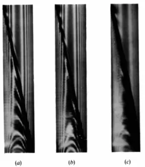
fringes in the experimental image. Fig. 3(a) is the corresponding computed image with a 0.001 mm wide 'theoretical' entrance slit, and the Burgers vectora/3
[111]. The comparison is satisfactory and all other tentative Burgers vectors gave less resemblance. For instance, Fig. 3(b) is the same computed section with the Burgers vectora/2
[110]. It can be seen that the distribution and the shape of the fringes do not fit the experimental topograph: the fringes are too abruptly curved and the bottom of the image is white instead of black. In Fig. 3(c) the theoretical slit width was increased to 0-017 mm (maxi- mum value allowed by the program) and both parallel and perpendicular polarizations of the X-ray beam were intro- duced in the computation, to get more realistic conditions. The Burgers vector was againa/3
[111]. Here the corre- spondence between experimental and theoretical images is quite good.These results confirm the existence of Burgers vectors along (111) in GaAs. Such a direction of Burgers vector is usually invoked for partial dislocations in f.c.c, structures, but these dislocations are associated with a stacking fault. In
o.lmm
i •
Fig. 2. Section topograph, g = 7140.
our case, the resolution of the topographs and of the related simulation does not allow one to decide whether the defect is a perfect a r l 11] dislocation (high-energy defect) or a com- plex defect involving two or more Frank partials associated with stacking faults. It must be recalled here that the defects involved in this study are growth defects and not purely stress-induced ones. In addition, the high concentration of In may induce the formation of particular defects, as happens in Te-doped GaAs where condensation of Te along {111} planes induces complex stacking faults (Maksimov, Ziegler, Khodos, Snighiryova & Shikhsaidov, 1984). Finally, it must be pointed out that Burgers vectors along ( 1 1 1 ) have already been observed within grain boundaries in Czochralski-grown Si (Bourret, Desseaux-Thibault & Lancon, 1983).
This study demonstrates the usefulness of computational imaging techniques when the usual criteria of identification of defects do not lead to straightforward conclusions, and it shows again the influence of dopants on defect structure in semiconductors, particularly in I I I - V compounds.
R e f e r e n c e s
AUTHIER, A., MALGRANGE, C. 8/; TOURNARIE, M. (1968).
Acta
Cryst.
A24, 126-136.BOURRET, A., DESSEAUX-THIBAULT, J. & LANCON, F. (1983).
J. Phys. Colloq.
4, 9, 44, 15-24.DUSEAUX, M., SCHILLER, C., CORNIER, J. P., CHEVALIER, J. P. & HALLAIS, J. (1983).
J. Phys. Colloq.
4, 9, 44, 397-407. EPELBOIN, Y. (1974).J. Appl. Cryst.
7, 372-377.MAKSIMOV, S. g., ZIEGLER, M., KHODOS, I. I., SNIGHIRYOVA, I. I. ~ SHIKHSAIDOV, M. SH. (1984).
Phys. Status Solidi A,
84, 79-86.
PICHAUD, B., BURLE-DURBEC, N., MINARI, F. DUSEAUX, M. (1985).
J. Cryst. Growth,
71, 648-654. TANNER, B. K. (1976).X-ray Diffraction Topography.
Oxford: Pergamon Press.
(a) (b) (c)
Fig. 3. Computed section topographs. (a) b =