HAL Id: hal-00905635
https://hal.archives-ouvertes.fr/hal-00905635
Submitted on 3 Dec 2013
HAL is a multi-disciplinary open access
archive for the deposit and dissemination of
sci-entific research documents, whether they are
pub-lished or not. The documents may come from
teaching and research institutions in France or
abroad, or from public or private research centers.
L’archive ouverte pluridisciplinaire HAL, est
destinée au dépôt et à la diffusion de documents
scientifiques de niveau recherche, publiés ou non,
émanant des établissements d’enseignement et de
recherche français ou étrangers, des laboratoires
publics ou privés.
Immersive front-projection analysis using a
radiosity-based simulation method
Julien Dehos, Eric Zéghers, Laurent Sarry, François Rousselle, Christophe
Renaud
To cite this version:
Julien Dehos, Eric Zéghers, Laurent Sarry, François Rousselle, Christophe Renaud. Immersive
front-projection analysis using a radiosity-based simulation method. Virtual Reality, Springer Verlag, 2014,
18 (2), pp.117-128. �10.1007/s10055-013-0233-x�. �hal-00905635�
Manuscript - Accepted in Virtual Reality
Immersive front-projection analysis using a
radiosity-based simulation method
J. Dehos
LISIC, Universit´e Lille-Nord de France, ULCO, Calais, France
Tel.: +33-3-21-46-56-52
[email protected]
´
E. Z´eghers
Universit´e d’Auvergne, France
L. Sarry
ISIT, Universit´e d’Auvergne, France
F. Rousselle
LISIC, Universit´e Lille-Nord de France, ULCO, Calais, France
C. Renaud
LISIC, Universit´e Lille-Nord de France, ULCO, Calais, France
September 17, 2013
Abstract
Video-projectors are designed to project onto flat white diffuse screens. Over the last few years, projector-based systems have been used, in virtual reality applications, to light non-specific environments such as the walls of a room. However, in these situations, the images seen by the user are affected by several radiometric disturbances, such as interreflection. Radiometric compensation methods have been proposed to reduce the disturbance caused by interreflection, but nothing has been proposed for evaluating the phenomenon itself and the effectiveness of compensation methods.
In this paper, we propose a radiosity-based method to simulate light transfer in immersive environ-ments, from a projector to a camera (the camera gives the image a user would see in a real room). This enables us to evaluate the disturbances resulting from interreflection. We also consider the effectiveness of interreflection compensation and study the influence of several parameters (projected image, projec-tion onto a small or large part of the room, reflectivity of the walls). Our results show that radiometric compensation can reduce the influence of interreflection but is severely limited if we project onto a large part of the walls around the user, or if all the walls are bright.
user or camera
projec tor
room (top view)
reflection reflection opaque walls med ium med ium
Figure 1: Immersive front-projection: multiply-reflected light (red) can greatly impact once-reflected light (blue).
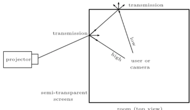
user or camera transmission transmission projector high lo w semi-transparent screens
room (top view)
Figure 2: Immersive rear-projection (CAVE):
multiply-reflected light can only slightly impact once-transmitted light.
1
Introduction
1.1
Motivation
Video-projectors are designed to project images onto specific screens. Since the rise of home-cinema and multimedia presentation, video-projectors have become widely affordable devices, so that they are now also used for other applications. One of these applications consists in projecting images onto a non-specific screen like a non-uniformly colored wall [10]. A camera is then used to automatically modify the projected image so that the visible image does not seem affected by the colors of the ”screen”. This technique, called radiometric compensation, has been improved in different ways [5].
For instance, radiometric compensation has been used to project onto complex screens, such as several walls of a room, to immerse the user into the projected image [24, 6]. Such systems, called immersive front-projection systems, can be built quite easily using a few affordable devices. Other immersive front-projection systems exist for quite a long time (c.f. the CAVE system [7]) but use rear-projection, through semi-transparent specific screens. Immersive rear-projection systems can perform very convincing immersion but are difficult and expensive to build.
Therefore, immersive front-projection systems are interesting but they suffer from interreflection between surfaces. Indeed, if we put a video-projector in a closed room, a large part of the projected light is reflected several times between surfaces before reaching the user (or the camera used to calibrate the system, see Fig. 1).
The problem is that the light that is not once-reflected toward the camera, is reflected toward other positions in the room, and thus affects the visible environment. Immersive rear-projection systems such as CAVEs are less sensitive to this problem because the light that does not reach the user (or the camera) reaches one of the semi-transparent screens, then mainly exits the projection room (see Fig. 2).
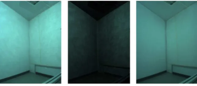
To illustrate the importance of the phenomenon, we applied the method described in [18] to an immersive front-projection system [2]. This enables us to separate the projected light into a directly reflected component and an indirectly reflected component (interreflection). The left hand side of Fig. 3 shows the real scene, lit by projecting a white image onto all the walls of the room. The middle of the figure shows the light emitted by the video-projector and reflected once by the screen (the walls of the room) toward the camera. The right hand side of the figure is the remaining light, i.e. light emitted by the video-projector and reflected multiple times by the screen (interreflection) before reaching the camera. Since we want to display an image (by immersive front-projection), we need a high proportion of directly reflected light and only negligible indirectly-reflected light (disturbance). Unfortunately, this is not the case.
non-Figure 3: Importance of interreflection under immersive front-projection. Left: real scene lit by a video-projector. Middle: light reflected once toward the camera. Right: light reflected multiple times before reaching the camera (interreflection).
planar surfaces [13, 15, 22]. Theoretically, we just have to obtain and invert the light transport matrix [19, 20] which characterizes how each projector pixel influences each camera pixel. In practice, though, the light transport matrix of a projector-camera system is difficult to obtain due to the huge size of the matrix. Furthermore, considering each projector pixel individually leads to very noise-sensitive results. A lot of work has been done to overcome these practical difficulties. In this paper, the motivation is to determine in which conditions (geometry of the room, full or partial immersion. . . ) interreflections can be compensated effectively, assuming all practical difficulties are solved.
1.2
Contribution
The aim of this paper is to characterize how light interreflection affects the visible image in an immersive front-projection system, to analyze the influence of several parameters (geometry of the room, full or partial immersion. . . ) and to characterize the effectiveness of interreflection compensation. To our knowledge, this work has not been performed despite being important as it can validate the relevance of compensation methods.
First, we propose a method to simulate the illumination resulting from immersive front-projection. This method is based on the radiosity method [11] (which simulates light transfer between surface patches) and also computes the light emitted by the video-projector and the light received by the camera.
We then present a simple compensation method consisting in inverting the projection. This implements the classic compensation scheme: compute a compensation image that, when projected, gives a visible image expected to be close to the desired image. This method does not aim to be implemented in a real system but to simulate compensation in a controlable environment with no practical difficulties such as projector non-linearities, camera noise. . .
Finally, based on the previous methods, we present an analysis of interreflection during immersive front-projection. We define a test scene and study the influence of several parameters on the resulting projection, with and without compensation. This makes it possible to predict the potential quality of an immersive front-projection system.
2
Related work
To our knowledge, the problem considered in this paper has not yet been raised explicitly. However, some related work can be found in the literature.
Langer proposed a theoretical study of light interreflection [14] where he shows how interreflection can affect color appearance. However, this work only deals with interreflection in a sphere cut by a plane and lit by a uniform diffuse source, which is too restrictive to solve our problem.
Rendering methods such as radiosity [11] or ray-tracing [9] can simulate light transport in a given scene. However, these methods need to be modified to simulate video-projection: in the case of ray-tracing, the
video-projector has to be implemented as a particular light source; in the case of radiosity, the projected light has to be converted into radiosity emitted on patches.
Image processing sometimes deals with the interreflection issue, for instance in image-based reconstruction methods (shape from shading [25], shape from interreflection [16]). In particular, Nayar et al. propose a method for using interreflection to reconstruct the shape of diffuse concave objects [16]. However, our problem is different since we know the geometry of the scene and want to characterize the influence of interreflection on a projected image.
Finally, interreflection has been considered in computer vision methods. Nayar et al. propose a method to separate once-reflected and multiply-reflected light in any scene lit by a video-projector [18]. However, their method requires the scene to be lit by a uniform projected image and, more importantly for our purposes, it does not deal with compensation.
Bimber et al. propose a reverse radiosity approach to compensate indirect scattering for immersive projection displays [4]. Their approach differs from ours in several ways. First, they aim to provide a compensation method for real systems whereas we propose a method to simulate and analyse the interreflec-tion phenomenon. Moreover, the compensainterreflec-tion method itself is quite different: they propose an iterative algorithm with a texture-based implementation whereas we propose an analytical algorithm with an imple-mentation based on geometric primitives.
Mukaigawa et al. propose a compensation method which is quite similar to ours [15]. However, here again, their goal (providing a pratical compensation method) is different from ours (simulate and analyse the interreflection phenomenon). Therefore, they do not propose a full compensation-projection-analysis scheme.
Wetzstein and Bimber propose a radiometric compensation method for projector-camera systems that accounts for interreflection [22]. Their method consists in acquiring the light transport matrix (from projector to camera) and then inverting it. Thus, they are able to compensate interreflection produced by projecting onto a non-convex screen (for instance, two walls of a room). However, their method has not been tested for highly-immersive projection where interreflection is a greater factor.
Bai et al. show the duality between forward and backward light transport [3]. This allows them to use standard rendering algorithms in the inverse light transport framework, and to propose a compensation algorithm. However, their work focuses more on the compensation method than on the quality of the final result. Moreover, no experimental results with highly-immersive projection are given.
Finally, Sheng et al. propose a theoretical description of the compensation problem and an optimization-based resolution method [21]. However, here again, experimentation was not performed using fully-immersive scenes (only room models with no ceiling).
3
Background
3.1
Radiometric compensation
Assuming we have a geometrically calibrated projector-camera system (see Table 1 and Fig. 4), we call Lp
the projected image and Lc the resulting image seen by the camera (or the user) :
Lp −→
projectionLc
We call L the image we want to display using the system. Due to radiometric perturbations (such as interreflection), if we project L (i.e. LP = L), we will not see the correct image (i.e. Lc6= L).
Radiometric compensation [17], consists in computing a compensation image L′ p: L′ c= L −→ compensationL ′ p
such that if we project L′
i a surface patch
k a pixel (projector or camera) ”seeing” patch i K the set of all pixels ”seeing” patch i
θk angle between the direction to pixel k and the
normal of patch i Lk
p radiance emitted by a pixel k of the projector
(in projection step) Lk
c radiance seen by a pixel k of the camera (in
projection step)
Bi radiosity of patch i (in projection step)
Ei emitivity of patch i
Bk
i radiosity of patch i seen by pixel k
Ek
i emitivity of patch i produced by pixel k
ρi reflectivity of patch i
Fij form factor between patch i and patch j
L′ k p, L
′ k
c. . . equivalent symbols in compensation step
radiosity flux emitted by a patch for a unit of area radiance flux emitted for a unit of area and for a unit
of solid angle
Table 1: Main symbols and definitions. Here, we assume that the projector and the camera have the same geometric and optical characteristics so that a pixel at the position (x, y) in the projector image is seen at the position (x, y) in the camera image.
In practice, compensation is limited by two difficulties. Firstly, the compensation parameters are gen-erally measured using the projector-camera system, which is sensitive to measurement noise. Secondly, the computed compensation image is not always displayable (saturation, negative values) so that it has to be modified (clamping, tone mapping. . . ) before projection. The motivation of this paper is to evaluate the quality of the visible image, after compensation and projection, in a fully known environment (which does not imply noisy measurements).
3.2
The radiosity method
The radiosity method is a well-known method to simulate light transfer in a virtual 3D scene. Assuming all emitters and reflectors are Lambertian (i.e. diffuse : they emit or reflect light constantly over all directions of the hemisphere), we can compute interreflections using the discrete constant radiosity equation [9]:
Bi= Ei+ ρi N
X
j=1
FijBj (1)
where Bi is the visible radiosity of patch i, Ei is the radiosity emitted by patch i, ρi is the reflectivity of
patch i, N is the number of patches and Fij is the form factor between i and j (proportion of energy leaving
patch j and arriving at patch i). Using matrix formulation, we have B = E + GB (where Gij = ρiFij), i.e.
(I − G)B = E (2)
As described in the next section, this equation can be used to simulate the whole system (projector, interreflection, camera) and to propose a simple compensation method.
Bi θk p θk c ~n Lkp Lk c Projector Camera
Figure 4: Illustration of a calibrated projector-camera system. In this paper, we assume that the projector and the camera have the same geometric and optical characteristics (same position, orientation. . . ), therefore we have θk
p= θkc = θk.
4
Simulation method
4.1
Hypothesis
We assume that we have a virtual 3D scene, for instance a room. A virtual video-projector set inside the room is the only light source of the scene. The video-projector projects an image onto several different surfaces of the room (sections of the walls, ceiling and floor). To satisfy the discrete constant radiosity method, we assume that materials are Lambertian and that the room is subdivided into small constant radiosity patches. In fact, Lambertian materials correspond to the easiest configuration for compensation because interreflections (i.e. disturbances) are distributed in the whole scene and not concentrated in a small area. Finally, we assume that both virtual projector and virtual camera share the same geometric and optical characteristics (position, orientation, focal length, image size. . . ). This enables us to consider that the pixels of the projector and the pixels of the camera are geometrically aligned and correspond to comparable radiance values.
4.2
Simulation of the projection
4.2.1 Emitted radiosity
To apply the radiosity method, we first have to convert the light projected by the video-projector (Lp) into
radiosity emitted by patches (E). We assume that projector pixels are uniform, i.e. any pixel emits the same radiance for a given level. Let Lk
p be the radiance emitted by the video-projector at a given pixel k. If the
corresponding light reaches a single patch i, the corresponding reflected radiance is: Lk r= ρi π cos θ kLk p (3)
where ρiis the reflectivity of patch i and θk is the angle between the patch normal and the incident direction.
The radiosity of a patch is the flux emitted by this patch for a unit of area, and the radiance is the flux for a unit of area and for a unit of solid angle [9]. Thus, radiosity can be obtained by integrating radiance over the hemisphere. Since we assume that the emitters and the reflectors are Lambertian, the radiosity emitted by patch i, which results from the projection of the pixel k, is:
Ek
i = πL
k
r= ρicos θkLkp (4)
Note that the patches composing the room do not emit light but only reflect light coming from the video-projector. To simplify, we have used “emitted radiosity” to describe the amount of light travelling from the video-projector to the patch and then reflected by the patch.
Finally, we get the radiosity emitted by i, which comes from the projected image, using: Ei= ρi #K X k∈K cos θkLk p (5)
where K is the set of pixels whose light reaches patch i and #K is the size of K. Note that this equation requires every patch of the scene to be either fully lit by the video-projector or fully unlit.
Equation 5 enables us to convert radiance projected by the video-projector into radiosity emitted by the patches making up the scene. This radiosity can then be used to compute light transfer using the radiosity method, as explained below.
4.2.2 Light transfer matrix
To apply the radiosity method, we need the light transfer matrix G characterizing how the radiosity of each patch is scattered to the other patches. The reflectivity ρiis a given parameter of the scene. The form factors
F can be computed from the geometry of the scene. The literature gives numerous analytical formulae for computing form factors depending on the geometrical configuration of the patches considered [12]. However, except for a few particular configurations, these formulae are complex and therefore difficult to implement and expensive to evaluate, which is why numerical methods are frequently used to estimate form factors. In our implementation, we use the numerical quadrature method which makes the simulation method useable for any configuration (moreover, this method enables us to account for occlusion using a visibility test). 4.2.3 Visible radiosity
Knowing the emitted radiosity E and the light transfer matrix G, we now have to find the visible radiosity B such that (I − G)B = E (Equation 2). Assuming the hypothesis described in Section 4.1 (discrete constant radiosity, Lambertian emitters and reflectors), and given that light transfer is energy-conservative, we can show that the matrix (I − G) is diagonally dominant therefore invertible [9]. Thus, we can determine visible radiosity by computing:
B = (I − G)−1E (6)
A more numerically efficient method is to solve the linear system (I − G)B = E for B using an iterative method such as the Jacobi method or the Gauss-Seidel method.
4.2.4 Camera image
According to the hypothesis set out Section 4.1, the radiance corresponding to the intensity of one pixel is the same for every pixel (camera and video-projector). Moreover, since the patches are perfect Lambertian reflectors, the radiance emitted from a patch is constant over different directions and over the surface of the patch. The radiance measured by the camera for a pixel k corresponding to patch i of radiosity Bi is
therefore:
Lk
c =
Bi
π (7)
Using this equation, we can compute an image of the scene, thus simulating the projection process. However, the accuracy of this simulation remains limited by patch size. Indeed, a patch is generally associated to several projector/camera pixels. To get a more accurate camera image, we propose to break visible radiance into two components: the radiance resulting from interreflection (defined at patch level) and the radiance emitted by the video-projector and reflected once toward the camera (defined at pixel level). Of course, this is an approximation since the discretisation with patches introduces artifacts (better results can be obtained by reducing patch size or by prefiltering patch radiosity). The first component is obtained by computing the radiosity produced by interreflection, i.e. B − E. For the second component, let Lk
p be the radiance emitted
by the video-projector for pixel k. The radiance arriving onto the patch is therefore Lk
pcos θk where θk is
the angle between the surface normal ~n and the incident direction (see Fig. 4).
The radiance reflected by the corresponding patch i of reflectivity ρi is then Lkpcos θkρi/π. Finally, total
radiance measured by the camera pixel is: Lk c = Bi−Ei π + ρi π cos θ kLk p (8)
If we assume that the intensity response function of the camera is linear, then the intensity returned by the camera is related to the visible radiance via a constant factor that depends on the sensitivity of the photo-detectors and on exposure time. Thus, in our application, we can arbitrarily set this factor to π, which gives the simpler equation:
Lkc = Bi−Ei+ ρicos θkLkp (9)
4.3
Interreflection compensation
The previous paragraphs explain how to compute the image seen by a camera in a room where a given image is projected by a video-projector. This enables us to predict how interreflections affect the visible image. Furthermore, if we apply a compensation method to the given image, before the projection, we can predict the visible image and the efficiency of the compensation method. There are several compensation methods in the literature. Basically, they consist in inverting the projection. Here, we describe how to do that simply, by using the radiosity method.
Knowing the desired camera radiance L′k
c, we have to compute the corresponding visible radiosity B ′
, then the corresponding emitted radiosity E′
and, finally, the video-projector radiance L′k
p to be projected.
Recall that, in Lambertian cases, the radiosity of patch i seen by camera pixel k is: B′ k
i = πL
′ k
c (10)
where L′ k
c is the radiance of the camera pixel k.
Therefore, total radiosity of the patch is: B′ i= π #K X k∈K L′k c (11)
As explained Section 4.2.4, the acquisition process implies that the captured image gives the radiance of the scene to a factor, which we have arbitrarily set to π here. The previous equation can thus be simplified:
B′ i= 1 #K X k∈K L′k c (12)
This gives us the radiosity that has to be visible in the scene. The corresponding emitted radiosity that patches have to provide is then:
E′
= (I − G)B′
(13) Since, emitted radiosity comes from the Lambertian reflection of light projected by the video-projector, the radiance the video-projector has to emit is:
L′k r= E′ i π (14) i.e. L′k p = πL′ k r ρicos θk = E ′ i ρicos θk (15) where L′ k
p is the radiance provided by the video-projector, E ′
i is the emitted radiosity corresponding to the
considered pixel, ρi is the reflectivity of the patch and θk is the angle between the patch normal and the
direction to the video-projector.
Assuming that a given patch receives several pixels, we can compute a more accurate compensation image with: L′ k p= E′ i ρicos θk L′ k c B′ i (16) where L′ k
c is the radiance of the desired image and B ′
i the radiosity of the patch corresponding to the
considered pixel. This equation confers L′ k pand E
′
iwith the same proportionality as L ′ k
c and B ′
i. Here again,
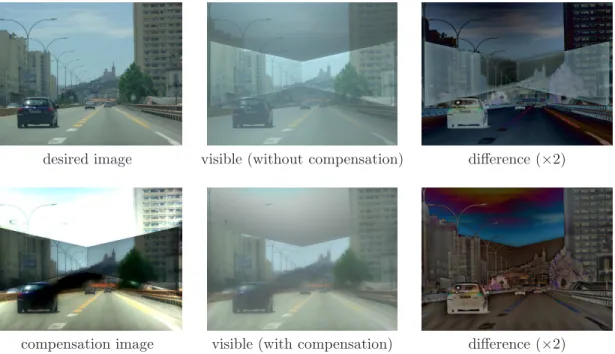
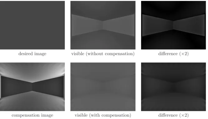
desired image visible (without compensation) difference (×2)
compensation image visible (with compensation) difference (×2)
Figure 5: Immersive front-projection results with and without compensation for the reference configuration.
5
Results and analysis
We now use the method described in the previous section to analyze the influence of interreflection during immersive front-projection. We begin by presenting the scene used in our tests, and then give the criteria used for quantifying interreflection. Finally, using these criteria, we analyze the influence of several parameters.
5.1
Test scene
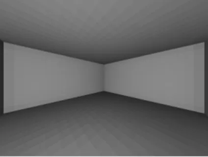
The scene used for our immersive front-projection simulation, is a (virtual) room sizing 4.8 × 4.8 × 2.4 m. The materials are Lambertian and the surfaces (walls, ceiling, floor) are subdivided into rectangular patches. In our implementation, the scene is subdivided into 576 patches and form factors are computed using 9 samples per patch and per form factor. The virtual video-projector is placed inside the room toward a corner. To satisfy the hypothesis of the simulation method, the virtual camera and the virtual video-projector share the same geometric and optical characteristics. This gives us a direct match between the camera image and the video-projector image, for every pixel.
5.2
Quantification of interreflection
The first criterion we use to quantify the interreflection produced by immersive front-projection is the amount of “indirect” radiosity, i.e. Bi−Ei. This gives us a notion of error: a high value indicates that interreflection
greatly disturbs the projection.
The second criterion is the contribution of emitted radiosity to visible radiosity, i.e. Ei/Bi. This gives us
a notion of “useful” information (like the signal-noise ratio used in signal processing): a high ratio indicates that interreflection only slightly disturbs the projection.
To evaluate the efficiency of the compensation, we first consider the amount of emitted radiosity needed to compensate interreflection. Indeed, the required emitted radiosity affects the compensation image to be projected. If the compensation image does not fit the range of the video-projector (negative or over-high pixel values), then it cannot be projected, meaning interreflection cannot be fully cancelled out in the camera
0 50 100 150 200 250 reference configuration indoor scene gray image immersion 25 % ceiling removed reflectivity 0.4 pixel values
Figure 6: Influence of projection configuration on the radiosity generated by interreflection (Bi−Ei)
(min, mean and max values).
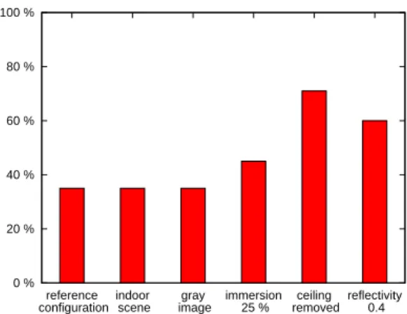
0 % 20 % 40 % 60 % 80 % 100 % reference configuration indoor scene gray image immersion 25 % ceiling removed reflectivity 0.4
Figure 7: Influence of projection configuration on the contribution of emitted radiosity to visible ra-diosity (Ei/Bi). -150 -100 -50 0 50 100 150 200 250 reference configuration indoor scene gray image immersion 25 % ceiling removed reflectivity 0.4 pixel values
Figure 8: Influence of projection configuration on the radiosity that patch i has to emit to compensate for interreflection (Ei in the compensation image)
(min and max values).
0 20 40 60 80 100 120 reference configuration indoor scene gray image immersion 25 % ceiling removed reflectivity 0.4 pixel values
Figure 9: Influence of projection configuration on the difference between the desired image and the visible image without (red) and with (blue) com-pensation (mean value and standard deviation).
Figure 10: Share of light once-reflected toward the camera in total visible light (once-reflected + interreflec-tion), when projecting a white image. A dark pixel reveals that the light comes mostly from interreflection.
image. Note that this problem can be solved by linearly remapping the compensation range to the range of the video-projector but this step entails a loss of contrast in the camera image.
Finally, the last criterion we use to evaluate compensation efficiency is to compare the desired image with the camera image (with or without compensation). This gives us a per-pixel error, from which we can compute max error, mean error and standard deviation.
5.3
Reference configuration
In the configuration we use as a reference, materials have a reflectivity of ρ = 0.7 (i.e. the reflectivity of snow, which is high). The video-projector image is projected onto about 50% of the surface of the room. Finally, the projected image is a photo of an outdoor scene (with pixel values in [0, 255]3), where mean pixel
value is 123, and standard deviation is 46. The result of the projection with and without compensation is shown in Fig. 5. The quantification of interreflection is given in Figs. 6, 7, 8 and 9.
As illustrated in Fig. 5 (top row), interreflection greatly affects the image made visible with the immersive front-projection system. Thus, the different surfaces of the room are clearly visible. According to our quantification criteria, the radiosity of every visible patch produced by interreflection is between 43 and 153 (averaging 71) (see Fig. 6).
The radiosity that a patch has to emit is related to the radiance that the video-projector has to project, according to Lambertian reflection. This implies that, to provide the same radiosity, the video-projector should project more light onto a quasi-parallel patch than onto an opposite-facing patch. This explains why the compensation image is saturated in the area that is projected onto the ceiling. In fact, if we project a white image, only an overall 35% of the visible light is reflected once toward the camera (and therefore useful for the projection). Moreover, this proportion can vary significantly from pixel to pixel (see Fig. 10). As illustrated in Fig. 5 (bottom row), compensation can effectively reduce interreflection disturbance but is strongly limited by the level of saturation in the compensation image. Indeed, in order to set the visible radiosity of patches in the desired range [0, 204], the corresponding radiosity to be emitted should range from −76 to 153 (see Fig. 8). Of course, the video-projector cannot emit negative light, so compensation cannot be done completely. Thus, in the desired image, the pixels that project onto the ceiling are too bright to enable compensation (see Fig. 5). The compensation image is saturated but there is still not enough light. Similarly, above the car on the left, the desired image is too dark too be displayed. Interreflection still delivers too much light even when the video-projector projects the minimal light for this region. Theoretically, the video-projector would need to project negative light onto this area in order to fully achieve compensation. Finally, Fig. 5 (right column) shows that the visible image with compensation is globally closer to the desired image (mean error: 27, standard deviation: 12) than the visible image without compensation (mean error: 32, standard deviation: 18) (see Fig. 9).
desired image visible without compensation visible with compensation Figure 11: Immersive front-projection results with and without compensation for a second desired image (indoor scene).
5.4
Influence of the projected image
To determine the influence of the projected image, we run the simulation using another target image, a photo of an indoor scene (see Fig. 11). This image is darker (mean value: 102, reference configuration: 102) and more contrasted (standard deviation: 52, reference configuration: 46) than the image used in the reference configuration.
Here again, interreflection produces strong radiosity, between 43 and 140 (averaging 71). The visible image without compensation is disturbed by the projection, making the projection room clearly visible.
The visible radiosity corresponding to the desired image covers the whole dynamic range [0, 255]. The radiosity to be emitted, to perform compensation, ranges from -115 to 217, which cannot be emitted by the video-projector. However, the visible image with compensation is visually quite satisfactory. The criteria we have defined to evaluate the difference between the desired image and the visible image indicate that, in this configuration, compensation increases the average difference (without compensation: 27, with compensation: 32) but decreases its standard deviation (without compensation: 20, with compensation: 17). In other words, the difference is globally greater with compensation (as the video-projector cannot project the negative light needed for compensation) but less contrasted, thus yielding a visually better result (as our vision is more sensitive to variations than absolute values).
To verify that compensation is more efficient if the desired image is dark and has low contrast, we performed the simulation for a uniform gray image (mean value: 70, standard deviation: 0) (see Fig. 12).
In this configuration, the projected image is globally darker, therefore the video-projector emits less light and the radiosity resulting from interreflection is lower (between 28 and 64, averaging 46). The radiosity patches have to emit to display the desired image ranges from −48 to 48. The visible image is globally less close to the desired image with compensation (average difference: 21) than without compensation (average difference: 10). Here again, this can be explained by the fact that the video-projector cannot emit the negative light needed for compensation, hence the resulting globally over-bright image visible with compensation. However, the compensation still attenuates interreflection-related local variations (standard deviation with compensation: 3, without compensation: 8).
5.5
Influence of immersion
In the reference configuration, the image is projected onto 50% of the room surface. We now consider projecting onto 25% of the room surface (see Fig. 14 and 13).
Radiosity coming from interreflection is significantly lower (between 25 and 127, averaging 38). The visible image is clearly less disturbed (average difference: 21, reference configuration: 32). The share of emitted radiosity accounting for visible radiosity is higher (45%, reference configuration: 35%).
desired image visible (without compensation) difference (×2)
compensation image visible (with compensation) difference (×2)
Figure 12: Immersive front-projection results with and without compensation for a uniform gray image.
reference configuration 25% of the room surface room with no ceiling reflectivity ρ = 0.4 Figure 13: Simulation of the projection under various conditions.
desired image visible without compensation visible with compensation
Figure 14: Immersive front-projection results with and without compensation when projecting onto a smaller region (25% of the room surface).
desired image visible without compensation visible with compensation Figure 15: Immersive front-projection results with and without compensation when projecting in a room with no ceiling.
desired image visible without compensation visible with compensation
Figure 16: Immersive front-projection results with and without compensation using a material reflectivity of ρ = 0.4.
5.6
Influence of environment
The compensation methods proposed in the literature are generally tested using concave but partially open screens. For instance, in [21], an image is projected, from the top, onto a mock-up of a room with no ceiling. In configurations like this, light can escape through openings, which does not happen in a completely-closed room. To evaluate the impact of this phenomenon on interreflections, we applied our simulation method to a room with no ceiling (see Fig. 15 and 13).
Note that removing the ceiling has a major effect on interreflection. With no ceiling, the radiosity produced by interreflection ranges from 13 to 64, averaging 20 (v.s. with the ceiling: 43 to 153, averaging 71). The share of emitted radiosity in visible radiosity is twice as high (71%) and the compensation step proves very efficient (the average difference between desired image and visible image, with compensation, is about 6, with a standard deviation of 9). This reveals that interreflection is particularly strong if the projection room is totally closed.
5.7
Influence of reflectivity
The last parameter we consider is the reflectivity of the materials, which we now set to ρ = 0.4 (see Fig. 16 and 13).
Radiosity coming from interreflection is far lower (between 5 and 25, averaging 13) while the share of emitted radiosity is quite high (averaging 60%). However, the visible image is radically different from the desired image (average difference 83, standard deviation 37) and cannot be satisfactorily compensated (average difference 47, standard deviation 38).
6
Conclusion
In this paper, we propose to simulate and analyse an immersive front-projection system using a rendering method (radiosity). This makes it possible to quantify the impact of interreflections in the visible images, to identify major sources of interreflection and to predict the efficiency of a compensation method in a virtual projector-camera system (which, unlike real systems, does not suffer from noise).
The simulations we made show that interreflections can greatly disturb the visible image in an immersive front-projection system. To limit interreflections, the system should project onto a limited part of the walls only. The other parts of the walls should be dark, otherwise they would increase interreflections a lot, even if they are not lit by the projector directly.
If interreflections are not too important, radiometric compensation can reduce their impact on the visible image. However, if the desired image is too bright or too contrasted, the compensation image will have out-of-range values, therefore it will not be projected as it should and interreflections will affect the visible image.
Future work could valuably extend this study to non-Lambertian materials, which would make it possible to analyze more realistic configurations. However, this implies using another rendering method since the radiosity method presented here assumes that materials are Lambertian.
Finally, it would be interesting to use the proposed simulation method to evaluate the efficiency of more advanced compensation methods, such as content-dependent methods [23, 1]. This would be quite straightforward to implement since it just implies to change the compensation step.
References
[1] Ashdown M, Okabe T, Sato I, Sato Y (2006) Robust content-dependent photometric projector compen-sation. Proceedings of the 2006 Conference on Computer Vision and Pattern Recognition Workshop:6– [2] Astre B, Sarry L, Lohou C, Zeghers E (2008) Automatic calibration of a single-projector catadioptric
display system. IEEE Computer Society Conference on Computer Vision and Pattern Recognition [3] Bai J, Chandraker M, Ng T-T, Ramamoorthi R (2010) A dual theory of inverse and forward light
transport. Proceedings of the 11th European Conference on Computer Vision:294–307
[4] Bimber O, Grundhofer A, Zeidler T, Danch D, Kapakos P (2006) Compensating indirect scattering for immersive and semi-immersive projection displays. Proceedings of the IEEE conference on Virtual Reality:151–158
[5] Bimber O, Iwai D, Wetzstein G, Grundh¨ofer A (2008) The visual computing of projector-camera systems. ACM SIGGRAPH 2008 classes:1–25
[6] Bourke P (2008) Low cost projection environment for immersive gaming. Journal of Multimedia 3 (1):41– 46
[7] Cruz-Neira C, Sandin DJ, DeFanti TA (1993) Surround-screen projection-based virtual reality: the design and implementation of the cave. Proceedings of the 20th annual conference on Computer graphics and interactive techniques:135–142
[8] Fernando R, Kilgard MJ (2003) The Cg Tutorial: The Definitive Guide to Programmable Real-Time Graphics. Addison-Wesley Longman Publishing Co., Inc., Boston, MA, USA
[9] Glassner AS (1994) Principles of Digital Image Synthesis. Morgan Kaufmann Publishers Inc., San Fran-cisco, CA, USA
[10] Grossberg MD, Peri H, Nayar SK, Belhumeur PN (2004) Making one object look like another: Con-trolling appearance using a projector-camera system. IEEE Computer Society Conference on Computer Vision and Pattern Recognition (1):452–459
[11] Goral CM, Torrance KE, Greenberg DP, Battaile B (1984) Modeling the interaction of light be-tween diffuse surfaces. Proceedings of the 11th annual conference on Computer graphics and interactive techniques:213–222
[12] Howell J (1982) A catalog of radiation configuration factors. McGraw-Hill
[13] Habe H, Saeki N, Matsuyama T (2007) Inter-reflection compensation for immersive projection display. IEEE Computer Society Conference on Computer Vision and Pattern Recognition:1–2
[14] Langer MS (2001) A model of how interreflections can affect color appearance. Color Research & Ap-plication
[15] Mukaigawa Y, Kakinuma T, Ohta Y (2006) Analytical compensation of inter-reflection for pattern projection. Proceedings of the ACM symposium on Virtual reality software and technology:265–268 [16] Nayar SK, Ikeuchi K, Kanade T (1991) Shape from interreflections. International Journal of Computer
Vision 6:173–195
[17] NAYAR S, PERI H, GROSSBERG M, BELHUMEUR P (2003) A Projection System with Radiometric Compensation for Screen Imperfections. ICCV Workshop on Projector-Camera Systems
[18] Nayar SK, Krishnan G, Grossberg MD, Raskar R (2006) Fast separation of direct and global components of a scene using high frequency illumination. ACM SIGGRAPH 2006 Papers:935–944
[19] Sen P, Chen B, Garg G, Marschner SR, Horowitz M, Levoy M, Lensch HPA (2005) Dual photography. ACM Transactions on Graphics 24:745–755
[20] Seitz SM, Matsushita Y, Kutulakos KN (2005) A theory of inverse light transport. Proceedings of the Tenth IEEE International Conference on Computer Vision (2):1440–1447
[21] Sheng Y, Yapo TC, Cutler B (2010) Global illumination compensation for spatially augmented reality. Computer Graphics Forum 29 (2):387–396
[22] Wetzstein G, Bimber O (2007) Radiometric compensation through inverse light transport. Proceedings of the 15th Pacific Conference on Computer Graphics and Applications:391–399
[23] Wang D, Sato I, Okabe T, Sato Y (2005) Radiometric compensation in a projector-camera system based properties of human vision system. Proceedings of the 2005 IEEE Computer Society Conference on Computer Vision and Pattern Recognition Workshops (3):100–
[24] Yuen NPY, Thibault WC (2008) Inexpensive immersive projection. IEEE Virtual Reality Conference:237–240
[25] Zhang R, Tsai P-S, Cryer JE, Shah M (1999) Shape from shading: A survey. IEEE Transactions on Pattern Analysis and Machine Intelligence 21:690–706