Design and Fabrication of Retrofit E-Bike
Powertrain and Custom Lithium-Ion Battery Pack
by
Helena Wang
Submitted to the Department of Mechanical Engineering
in partial fulfillment of the requirements for the degree of
Bachelor of Science in Mechanical Engineering
at the
MASSACHUSETTS INSTITUTE OF TECHNOLOGY
un-C0 LC- (J
dC
June 2015
@
Helena Wang, MMXV. All rights reserved.
The author hereby grants to MIT permission to reproduce and to
distribute publicly paper and electronic copies of this thesis document
in whole or in part in any medium now known or hereafter created.
Signature redacted
Author ...
...
Department of Me anal Engineering
Certified
by...
May 19, 2015
Signature
redacted-Steve Banzaert
Technical Instructor
Signature redacted
Thesis Supervisor
A ccepted by ...
...
Anette Hosoi
Professor of Mechanical Engineering
Undergraduate Officer
Design and Fabrication of Retrofit E-Bike Powertrain and
Custom Lithium-Ion Battery Pack
by
Helena Wang
Submitted to the Department of Mechanical Engineering on May 19, 2015, in partial fulfillment of the
requirements for the degree of
Bachelor of Science in Mechanical Engineering
Abstract
A chopper-style bicycle was converted to a functional e-bike with electric powertrain, involving a hub motor, a custom power source, and throttle speed control. A custom battery pack was designed to meet system performance specifications and fabricated using individual lithium-ion cells. Overall design parameters included: form-factor of power source, system performance in terms of speed and weight, torque and power provided by the motor and power source, longevity of the battery pack, and compact integration of the powertrain into the existing bicycle.
Thesis Supervisor: Steve Banzaert Title: Technical Instructor
Acknowledgments
Thanks to Steve Banzaert, who, in agreeing to supervise my thesis, provided le-gitimacy and activation energy for documenting and completing the build process. Thanks also to Charles Guan and Jamison Go, who gave me invaluable advice and suggestions, and taught me nearly everything I know about hacking together electric vehicles from (nearly) scratch.
Melody Liu provided much-needed moral support and extra materials during long hours of soldering marathons. Frederick Moore helped me take last-minute measure-ments while I was an ocean away from my bike, and convinced me to stop questioning my engineering intuition and experience.
Special thanks to the Cambridge Bike Shop for putting the monstrous back wheel together despite slim tolerances and mismatched measurement, and for helping me clean up the bike into a presentable, rideable chopper.
Finally, I would like to thank the International Design Center at MIT for shop space and materials, and Techx for the funding that has made this, like my past technical projects at MIT, possible.
Contents
1 Introduction and Background
11
1.1 E-Bike Conversions . . . . 11 1.2 Hub Motors . . . . 12
2 Powertrain Design
13
2.1 Desired Specifications . . . . 13 2.1.1 Physical Constraints . . . . 13 2.1.2 Performance Goals . . . . 14 2.2 Logistical Considerations . . . . 15 2.2.1 C ost . . . . 15 2.2.2 T im e . . . . 153 Battery Pack Design and Fabrication
17
3.1 Introduction to Lithium-Ion Cells . . . . 173.2 Battery Design Specifications . . . . 17
3.2.1 Performance Specifications . . . . 17
3.2.2 Charging and Balancing . . . . 18
3.3 Circuit Routing and Soldering . . . . 18
3.3.1 Battery Cell Preparation . . . . 18
3.3.2 Wiring and Circuit Protection . . . . 21
3.3.3 Leads, Balance Wires, and Packaging . . . . 22
4.1 Drive wheel . . . . 25 4.2 Controller, Throttle, and Switch . . . . 25 4.3 Motor wiring and calibration . . . . 27
5 System Performance and Future Work
29
5.1 Adherence to Parameters . . . . 29 5.2 Drive Performance . . . . 30
5.3 Future Work . . . .
30
List of Figures
3-1 Unsanded(left) vs. sanded(center and right) cell terminals . . . . 19 3-2 Five cells glued in parallel, yielding 5p configuration . . . . 20 3-3 8s5p battery pack with black marks to indicate intended connections 20 3-4 Large soldering iron used for tinning large positive contacts . . . . . 20 3-5 Tinned positive and negative terminals of each battery cell . . . . 21 3-6 Wiring schematic for 8s5p battery pack, with resettable circuit
pro-tectors drawn as fuses, positive and negative main leads, and balance w ires . . . . 21 3-7 1A-2.5A resettable circuit protectors used to connect negative cell
ter-minals in 5p configuration . . . . 22 3-8 All negative terminals connected with circuit protectors and solder . 22 3-9 All contacts soldered, with protective layer of paper fitted over
termi-nals to prevent shorts and sparking . . . . 23 3-10 Protective layer of rubber foam over each soldered face of a battery pack 23 3-11 Battery packs wrapped with clear packing tape to secure foam and cell
alignment, and to protect power and balance wires from fatigue . . . 24
4-1 Controller and battery pack placement within bicycle frame . . . . . 26 4-2 System wiring schematic. Throttle switch is not pictured connected to
controller . . . . 26 4-3 3D-printed Hella battery master switch key . . . . 26 5-1 All components integrated into the now-functional e-bike. . . . . 29
Chapter 1
Introduction and Background
1.1
E-Bike Conversions
An electronic bicycle (e-bike) is a bicycle that has an electric drivetrain, involving a motor, a power source, a motor controller, and a method of speed control. Power input can be controlled by using a voltage divider/throttle, a pedal-assist sensor to provide driving power complementary to pedal input from the rider, or a combination of both.
While dedicated e-bikes can be purchased, it is often cheaper and more flexible to convert a non-electric bike to electric power. [6] Due to the universal standards of most bicycle designs, existing bicycles can usually be converted to electric power with minimal alterations. Methods of conversion include purchasing an e-bike conversion kit, or purchasing separate components for the powertrain. The latter method allows for more customization of the e-bike but also involves additional considerations for both electrical and physical compatibility of the chosen components. In this project, a bicycle was converted into an e-bike using a hub motor, controller, and custom battery pack.
1.2
Hub Motors
Wheel hub motors, commonly just called hub motors, are preferable to mid-drive motors in the context of e-bike propulsion because they eliminate need for external mounting and belts or chains for power transmission. Instead, the shaft of the motor serves as the axle when integrated into the drive wheel of the bicycle, and the rotor attaches to the tire and wheel rim via spokes. Hub motors can be either ungeared or geared, where the former provides direct drive to the wheel and regenerative braking capability at the cost of a heavier and larger motor, and the latter incorporates a planetary transmission within the hub that offers higher torque output and less rolling friction at the cost of more noise, wear, and expense.
Chapter 2
Powertrain Design
2.1
Desired Specifications
2.1.1
Physical Constraints
The bicycle used in this e-bike conversion was a non-standard, chopper-style bicycle: the Schwinn Stingray Chopper. A chopper-style bicycle differs from a standard bicycle by having a longer frame, a long front end with angled extended forks, relatively tall handlebars, and a lack of front and rear suspension. The rear wheel on this bicycle had a width of 4.25", which is well outside the range of the usual 0.7-2.4" width of most standard bikes. The unconventional wheel width led to concerns about the width of the rear dropout, which, at 6.75", was significantly wider than the stays for which hub motor shafts are generally designed. A hub motor with shaft length 7.67" was chosen, to ensure appropriate thread attachment length. Additionally, because the width of the rear wheel was greater than the width of the motor itself, the spokes would attach at an inverted draft towards the motor, recessing the motor within the width of the wheel rim. The sprocket and chain would be out of alignment if the motor was spoked in a centered position within the wheel rim, so spacers and uneven spoke alignment was required. Finally, the placement of components was designed to fit within the form-factor of the bike without external saddlebags or other storage attachments. The battery was designed to fit within the frame and the controller was
placed in front of the rear wheel.
2.1.2
Performance Goals
Initially, the top speed of the e-bike was designed in compliance with Massachusetts electric bicycle laws to not exceed 30mph, lest it become necessarily categorized as a motorcycle or motorized scooter and be subject to the appropriate legal constraints. This threshold was again lowered to 20mph to prevent antagonizing cyclicsts in the bicycle lane where this vehicle would likely be ridden. Desired power rating was determined using combined system weight of 120 kg and desired acceleration of 20mph in 5s:
m 2
P m x a (2.1)
dt
where P is power in watts, m is mass in kg, and a is average desired acceleration as described above. Equation 2.1, when calculated with the above system parameters, yields an average power requirement of 320W, which would be satisfied with a 350W motor. However, with additional considerations such as added weight, friction, drag, and grade climbing, a 500W motor was selected for the system instead. Battery capacity was determined using a desired range of 20 km, with an initial energy usage estimate of 20 Wh/km and battery voltage of 48V:
AE
=
(2.2)
where Ah is amp-hours of the battery pack, r is range in km, E is energy usage, and V is nominal pack voltage. Using the above battery parameters, desired capacity of the battery was determined to be 10 Ah.
2.2
Logistical Considerations
2.2.1
Cost
A total budget of $500 was available for the conversion of this e-bike, so the compo-nents were chosen in the most cost effective manner for minimal required performance, in order to minimize out-of-pocket cost. Materials were found instead of purchased as much as possible.
2.2.2
Time
Time constraints were also a significant factor in design of the system. Because the funding for the project was offered through MIT TechX in October, the final e-bike was due to be presented at xFair in the first week of February. As this project was initiated as an iterative design process, the components for the e-bike conversion were selected on their availablity and speed of acquisition, and assembly was maximized for immediate functionality rather than robustness. The e-bike was functional at the time of presentation as a proof-of-concept prototype, to be improved upon in future iterations.
Chapter 3
Battery Pack Design and Fabrication
3.1
Introduction to Lithium-Ion Cells
The battery cells used to make the battery packs in this e-bike conversion were A123 26650 Lithium Ion cells. Lithium-ion is the common name for LiFePo4 cells, which emerged in the early 1990s as a competitor to the nickel-cadmium battery mar-kets for portable equipment. Advantages of lithium-ion battery chemistry include typically twice the energy density of nickel-cadmium batteries, higher nominal cell voltage (3.6V vs. 1.2V for lithium-ion vs nickel-cadmium, respectively), and lower maintenance due to a lower self-discharge rate and lack of "memory" (need for volt-age cycling). Disadvantvolt-ages of lithium-ion battery chemistry include the need for a protection circuit to keep cell voltage and current within safe limits, and gradual deterioration of charge capacity when rapidly charged. [8]
3.2
Battery Design Specifications
3.2.1
Performance Specifications
As described in Section 2.1, the battery packs were designed to provide 48V nominal voltage, with lOAh capacity. Using nominal voltage and amp-hour ratings for A123 26650 cylindrical cells (3.3V, 2.5Ah) [7], battery configuration was determined to be
15 stacks of 5 cells in parallel (abbreviated as 15s5p). However, due to both space contraints and constraints on balancing capability of the charger (explained below in Subsection 3.2.2), the final pack was fabricated as an 8s5p and a 7s5p connected in series.
3.2.2
Charging and Balancing
Because of the aforementioned safety concerns in charging lithium-ion cells, the volt-age of each set of cells in a series configuration must be monitored to make sure there is no disrepancy in voltage across different sets of cells. This process, called voltage balancing, can be mediated by either a battery management system incorporated into the battery pack, or a balancing system incorporated into the battery charger. The latter method, external balancing, was chosen for use in this case in order to reduce the size and complexity of the battery pack by omitting an on-board battery
man-agement system.
However, this presented an additional difficulty in battery design, because most com-mercial balancing chargers will support up to 8s balance charging before an exponen-tial rise in charger price. To minimize project costs, an 8s dual balancing charger was purchased and the battery pack was split into two separate packs (one 8s and one 7s) that are connected in series to drive the e-bike and disconnected to charge separately
and simultaneously.
3.3
Circuit Routing and Soldering
3.3.1
Battery Cell Preparation
Seventy-five cells in total were required for this project. The individual A123 26650 cylindrical cells were acquired from a gracious donation made several years ago to an MIT project team. As a result of their age, they had acquired some reaction patina on the lead ends, and had varying levels of remaining charge.
First, the cells were separated by measured voltage, so that seventy-five cells of similar 18
states of charge could be used to build the battery packs. The selected battery cells were then sanded on both ends to remove the corrosion buildup and ensure a better electrical connection once soldered. The difference between unsanded, patina'd terminals and sanded terminals is visible in Figure 3-1 below.
Figure 3-1: Unsanded(left) vs. sanded(center and right) cell terminals
The cells were hot glued in 5p configuration (Figure 3-2) to aid in alignment when soldering. Then, the 8s and 7s packs were glued using the 5p stacks. The packs were designed with the cells aligned perpendicular to the frame of the chopper in order to fit within the open space while not interfering with the path of motion of the bicycle pedals.
The 8s pack is shown in Figure 3-3, with black marks indicating connections between cells in parallel and series.
Figure 3-2: Five cells glued in parallel, yielding 5p configuration
The negative terminals of the battery cells were tinned with a regular soldering iron. The positive terminals, however, required a very large iron tip due to the large
Figure 3-3: 8s5p battery pack with black marks to indicate intended connections
surface area and the rapid heat dissipation (Figure 3-4). The battery pack with tinned terminals is shown in Figure 3-5; smaller contacts are negative terminals.
Figure 3-4: Large soldering iron used for tinning large positive contacts
Figure 3-5: Tinned positive and negative terminals of each battery cell
3.3.2
Wiring and Circuit Protection
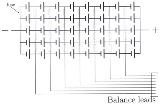
The wiring schematic for the 8s5p pack is presented in Figure 3-6. 1A-2.5A resettable circuit protectors (Figure 3-7) were placed where fuses are indicated in the schematic
between negative terminals of parallel cells, to provide overcurrent protection within the battery packs. All negative terminals were soldered first as a safety measure to prevent accidental shorting of the battery packs in case of contact with a metallic object. fuse
H
H
H
H
HF
HF
HF
HF
HF
HF
HF
HF
H
H
H
H
H
F-H
F
-I
F
H
F
F
Balance leacs
Figure 3-6: Wiring schematic for 8s5p battery pack, with resettable circuit as fuses, positive and negative main leads, and balance wires
protectors drawn
Figure 3-7: 1A-2.5A resettable circuit protectors used to connect negative cell terminals in 5p configuration
Figure 3-8 shows both battery packs after all negative terminals were soldered. Positive terminals were soldered using braided wire for a flatter profile while
maintain-ing good electrical contact. When soldermaintain-ing the positive terminals, extreme caution was taken to prevent arcing in case of accidental contact within the battery pack. Completed terminals were covered in paper to prevent contact with stray solder or other conductive material (Figure 3-9).
Figure 3-8: All negative terminals connected with circuit protectors and solder
Figure 3-9: All contacts soldered, with protective layer of paper fitted over terminals to prevent shorts and sparking
3.3.3
Leads, Balance Wires, and Packaging
Primary power terminals were attached according to Figure 3-6 for both battery packs, using 14g wire and Deans connectors; the connectors were chosen due to their non-reversible chirality. A separate bridge wire was then assembled to connect the two packs in series for power input to the rest of the system, preserving the charging modularity of the battery packs described in Subsection 3.2.2 while still allowing a
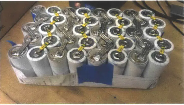
total power output of 48V as a complete system. Balance wires were also soldered to each stack of 5p cells and routed down the stacks of cells to terminate in a single connector for balance charging. Each battery pack was first covered on the terminal faces with a sheet of high-density rubber foam, as seen in Figure 3-10, in order to prevent damage to the soldered electrical connections and to prevent shorting. The battery packs were subsequently wrapped in clear packing tape, securing the foam and adding another level of reinforcement to the battery cell alignment, in addition to providing strain relief on the power and balance wires (Figure 3-11).
Figure 3-11: Battery packs wrapped with clear packing tape to secure foam and cell align-ment, and to protect power and balance wires from fatigue
Chapter 4
System Integration
4.1
Drive wheel
Keeping in mind the physical contraints as well as the performance requirements delineated in Section 2.1, the motor selected for the e-bike conversion was a 48V 500W geared hub motor with 7.55in total axle length and rear freewheel. Custom short spokes were used to lace the 7in diameter motor into the 20in rear wheel rim in a 36-spoke pattern. The bike frame was modified by bending the steel rear dropouts slightly towards each other to fit the drive wheel assembly safely.
4.2
Controller, Throttle, and Switch
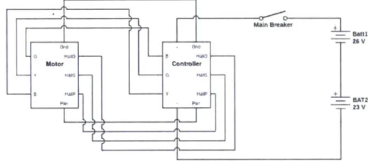
A mini brushless DC motor controller rated for 80A continuous and 160A peak current and 24-48V was purchased and modified to attach the appropriate power, throttle, motor, and sensor connectors.[4] The controller was mounted behind the seat tube; the battery packs were fit in front of the seat tube (Figure 4-1). A 0-5V thumb throttle was selected instead of a twist throttle due to the angled trajectory of the handlebars while turning on a chopper-style bike, which can cause unconscious torque on the throttle and a subsequent unwanted throttle adjustment. The throttle was mounted on the right side handlebar and connected to the proper inputs on the controller. The main breaker was placed in series between the battery and the controller (Figure 4-2,
Figure 4-1: Controller and battery pack placement within bicycle frame
throttle is not pictured). A 100A-rated Hella battery master switch from a previous electric vehicle project was recommissioned for this purpose. Because the key for the switch had been lost, a new one was 3D printed on an UP 3D printer, visible in Figure
4-3.
26V
I.,to Controler
r nAT2
Fp 'IT23V
Figure 4-2: System wiring schematic. Throttle switch is not pictured connected to controller
Figure 4-3: 3D-printed Hella battery master switch key
4.3
Motor wiring and calibration
Because hub motors are brushless, the three phase wires of the motor were cali-brated with the motor controller. After connecting the controller hall sensors to the corresponding wires from the motor, each configuration of the three phase wire com-binations on either end (6 comcom-binations of Yellow, Green, and Blue) were tested to find the proper phase configuration.
Chapter 5
System Performance and Future
Work
5.1
Adherence to Parameters
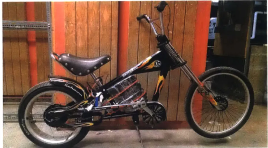
The final cost of the e-bike conversion components totalled $446. However, bicycle renovation costs and battery charger cost increased the cost of the project by about $250. All components were integrated to fit within the original frame of the bike with no large permanent modifications of the bicycle other than slight bending of the rear dropout. Final weight of the entire e-bike without rider was 36.3kg (80lbs). The completed project appears in Figure 5-1 below.
5.2
Drive Performance
The speed of the e-bike was recorded using a speed tracking app for Android smart-phones, which is dependent on GPS capability to calculate movement speed. The top speed achieved by the e-bike to be 10mph, achieved after 4s of acceleration on relatively flat ground. This top speed deviates significantly from calculated system specs. Possible sources of this difference are efficiency loss within the system, internal friction of the motor and rolling friction of the bicycle, and current limiting in the controller's programming.
Given that the motor's rated efficiency is 78%
[2],
total drive power can be estimated to be 390W of the total 500W. Furthermore, rolling resistance of a 4"-wide rear tire at the rated 35psi can be estimated by using the power needed to overcome a known rolling resistance value of 52W of a 20mm bicycle tire at 70psi under a 85kg load traveling at 18.6mph [1]. The power needed to overcome rolling resistance of a bike tire at half the pressure, half the speed, and four times the width of the measured values can be estimated to be around 50W. Coefficient of drag can be estimated to be 1.3, slightly greater than 1.1 for an upright cyclist [5], yielding an additional loss of 40W to overcome drag force at 10mph [3]. The remaining driving power of the system is approximately 300W, which is already lower than the estimated average power needed to sustain the speed and acceleration described in Section 2.1, and could account for the difference in performance from the design specifications.5.3
Future Work
Future goals for this project include a more robust, water-repellent battery casing, and evaluation of battery life/driving range and system power consumption to determine powertrain efficiency. Components may also be replaced to improve drive performance based on the findings of Subsection 5.1.2.
Bibliography
[1] Roues Artisinales. Tire Rolling Resistance. http://rouesartisanales.over-blog.com/article-1503651.html.
[2] Elifebike.com. Black Bafang BPMII 36V/48V 500W Rear Permanent Magnet
E-Bike DC Motor.
http://www.elifebike.com/peng/iview.asp?KeyID--dtpic-2013-9M-D4CE.9DMJF.
[3] Steve Gribble. An Interactive, Model-Based Calculator of Cycling Power vs Speed. http://www.gribble.org/cycling/power_v_speed.html.
[4] LLC Kelly Controls. Kelly KBS-E Brushless Motor Controller UseralAZs Manual. http:,//kellycontroller.com/mot/downloads/KellyKBS-EUserManual.pdf.
[5] Cycling Power Lab. Cycling Aerodynamics.
http://www.cyclingpowerlab.com/CyclingAerodynamics.aspx.
[6] Michelle Starr. Want a e-bike? build your own!, May 2014. [Online; posted 26-May-2014].
[7] A123 Systems. Nanophosphate High Power Lithium Ion Cell ANR26650 Data
Sheet. http://www.al23systems.com/Collateral/Documents/English-US/A123
[8] Battery University. Advantages and Limitations of the Lithium-Ion Battery.