A Design and Optimization Assistant for Induction Motors
and Generators
by
Ujjwal Sinha
B. Tech., Indian Institute of Technology, Delhi, India (1991) S.M., Massachusetts Institute of Technology (1993) Submitted to the Department of Mechanical Engineering in partial fulfillment of the requirements for the degree of
Doctor of Philosophy at the
MASSACHUSETTS INSTITUTE OF TECHNOLOGY June 1998
@ Ujjwal Sinha, 1998. All rights reserved.
The author hereby grants to MIT permission to reproduce and distribute publicly paper and electronic copies of this thesis document in whole or in part, and to grant others the
right to do so.
Author ... ... ... ...
Department of Mechanical Engineering February 18, 1998
Certified by... ...
Z James L. Kirtley Jr.
Professor, Electrical Engineering and Computer Science Thesis Supervisor
A c c e p te d b y ...0.0. .. ... .1. ... Accepted by... ... ... ..
Ain A. Sonin Chairman, Departmental Committee on Graduate Students
A Design and Optimization Assistant for Induction Motors and
Generators
by
Ujjwal Sinha
Department of Mechanical Engineering
Submitted to the Department of Mechanical Engineering on February 18, 1998, in partial fulfillment of the
requirements for the degree of Doctor of Philosophy
Abstract
This thesis presents a design methodology and software design tool, which are useful for the design of induction motors and synchronous generators. A user or designer specifies performance requirements and the system synthesizes a set of design parameters which meet those specifications. Optimization may also be performed by the designer with respect to any performance parameter, while keeping other requirements within specified limits.
Electric machine design is in general a "hard" problem, and most designers rely on their knowledge, experience, and intuition to design new motors or modify existing ones. Most of the problems encountered can be traced to non-linearities, coupled equations, cat-egorical variables, and presence of multiple objectives. Analysis of given design variables to compute performance parameters is comparatively easier using circuit equation analy-sis routines. The converse (syntheanaly-sis process), where we need to generate a set of design variables matching certain performance criteria, is a much harder problem. This is also the more common problem in a design scenario. We propose a two-step methodology to generate designs matching user requirements, and perform optimizations.
In the first step of our methodology, a Monte-Carlo based statistical approach is proposed to circumvent the aforementioned problems. The n-dimensional design space is first reduced to a smaller sub-space which is more likely to contain the desired solutions. A multivariate normal distribution is used to characterize this sub-space. Several designs are generated within this sub-space which allow a user to evaluate multiple design possibilities. All of these designs meet user requirements.
These designs are then also used as starting points for further optimization, in the second step of our methodology. A statistical function approximation tool called MARS (MultiVariate Adaptive Regression Splines) is used to "map" the relations between inputs and every performance variable. This map is then used during the optimization process for obtaining function values and gradients at all locations. A non-linear programming algorithm is used to perform all optimizations. Ideas from multiple objective optimization literature are used to account for multiple performance variables.
The proposed methodology is implemented in an industrial strength software system which allows a firm to perform multiple scenario analyses, automate the design process, perform optimizations, shorten development lead times, and react fast to customer requests. Several examples using industrial strength circuit analysis routines are presented, and their
results analyzed.
Even though this approach is applied to the case of induction motors, and synchronous generators, it is believed that the methodology is sufficiently general, and would be appli-cable to many design situations.
Thesis Committee:
Woodie C. Flowers, Committee Chairman Pappalardo Professor of Mechanical Engineering Roy E. Welsch, Committee Co-Chair
Professor of Statistics and Management Sciences James L. Kirtley Jr., Thesis Supervisor
In the memory of my mother Premi Sinha (1938-1986)
Acknowledgments
First and foremost, I would like to thank my thesis supervisor Professor James L. Kirtley Jr. for all his support and guidance throughout the project. Without his encouragement and inspiration at every stage, this project could not have been completed.
I would also like to thank the chairman and co-chair of my thesis committee: Professor Woodie Flowers, and Professor Roy Welsch, for their insightful comments, and helpful suggestions.
This thesis was supported by MagneTek Inc. Sincere thanks are due to Paul Lindhorst, for his help and support. To Bob Oesterlei, for helping and guiding me at every stage of the project over the last 5 years, and for being my virtual "co-advisor" on the project. To Bob Lambrecht, Chris White, Gail Sahlin, and Ed Eden for providing the software support and putting up with all my questions and requests!
Sincere thanks are due to Atul Adya, a close friend, for his support and help with the programming aspects of this project. To Karen, Vivian, and the staff and students of the Laboratory for Electromagnetic and Electronic Systems (LEES), I say a collective thank you.
I wish to thank Leslie Regan from the Mechanical Engineering Graduate Office and Dean Danielle Guichard-Ashbrook (International Students Office) who went out of their way to help me out during my first few days at MIT.
Most of all, thanks to my wife Shefali for all the love, care, and affection, and for being really understanding when the going was tough. And to my father and brother, whose constant support and encouragement have made a dream come true. To my entire family, I owe a debt of love and gratitude that I will never be able to repay.
Contents
1 Introduction 15
1.1 Motivation for the Project ... .... ... . 15
1.1.1 The Development Process . . . .... .. . . . 16
1.1.2 Automating the Development Process . ... 17
1.1.3 Summary of Goals for the Project . ... . . . 18
1.2 Project Organization and Background . ... . . . .19
1.2.1 Project Background ... ... 19
1.2.2 O bjective . . . ... . . . . . 20
1.2.3 Salient Features of Software System . ... . . . 21
1.2.4 Relationship with Industry ... . .. . . . . . . 22
1.2.5 Issues Addressed in this Thesis . ... . . . . 23
1.2.6 Case Study Implementation ... . . .. ... . 23
1.3 Literature Review and Critical Analysis . . . ... .. .. 24
1.4 Thesis Overview ... .. ... ... 27
1.5 Thesis Organization and Road Map . . . ... ... . 29
2 Problem Formulation, Alternative Approaches and Proposed Methodol-ogy 31 2.1 Problem Formulation ... .... ... 31
2.1.1 Modules of the NDA ... ... ... 31
2.1.2 The Design Process ... .. .... .. . . . . . . . . . . . 33
2.1.3 Design Synthesis ... ... 33
2.1.4 Important Issues Involved . ... . . . . 35
2.2 Alternative Approaches found in Literature ... . ... . 37
2.2.1 Expert Systems ... .... . . .. ... . 37
2.2.2 Grid Search ... ... .. ... .. 38
2.2.3 Linearizing the Mapping ... ... .... 38
2.2.4 Simulated Annealing ... .. . ... 39
2.2.5 Genetic Algorithms ... . . . . . ... 40
2.2.6 Monte Carlo Approach ... . . .. . . ... . . 42
2.3 Other Alternative Approaches ... . ... . 42
2.3.1 Conventional Optimization ... . . . . . . . . . 42
2.3.3 Neural Networks ... ... . 44
2.4 Proposed Methodology ... ... ... . 45
2.4.1 Monte Carlo Approach ... ... 45
2.4.2 Design Sub-Space Identification ... .. 46
2.4.3 Optimization ... ... .. 47
2.5 Recapitulation . . . ... . ... 48
3 Design Sub-Space Identification 49 3.1 The Monte Carlo Process ... ... 49
3.1.1 Using Monte Carlo for Design Synthesis . ... 49
3.1.2 Problems with Pure Monte Carlo ... . 50
3.2 Methodology for Sub-Space Identification . ... 52
3.2.1 Overview ... ... ... 52
3.2.2 Algorithm ... ... 52
3.3 Basic Statistical Concepts Used ... ... 55
3.3.1 Gaussian Distribution of Variables . ... 55
3.3.2 How Multi-Normal Distributions Help . ... 58
3.3.3 Means and Standard Deviations ... . 58
3.3.4 The Complete Process ... ... 59
3.4 Implementation and Results ... ... ... 60
3.4.1 Random Numbers ... ... . 60
3.4.2 Rule Sets ... . .. .... ... .... ... 60
3.4.3 Design Variable Space and Categorical Variables . ... 62
3.4.4 Example ... ... 63
3.4.5 Hit Ratio Improvement ... ... 63
3.5 Recapitulation . . . ... ... .. ... 65
4 Optimization 67 4.1 Multi-Objective Optimization ... ... .... . 67
4.1.1 Introduction ... ... .. 67
4.1.2 The Optimal Frontier ... ... 69
4.1.3 Techniques for Multi-Objective Optimization . ... 71
4.1.4 Chosen Formulation - Trade-Off Method . ... 73
4.1.5 Considerations ... . 74
4.1.6 Dominance . ... ... .... . ... 76
4.2 MARS as a Function Approximation Technique . ... 79
4.2.1 How These Techniques Help with Optimization . ... 80
4.2.2 Classification and Regression Trees ... ... ... . 81
4.2.3 MultiVariate Adaptive Regression Splines . ... . 83
4.2.4 Gradients from MARS Models . ... . . . . . 86
4.3 Proposed Methodology ... ... . . . . . . - - . . 88
4.3.1 Implementation . ... ... . . . ... 89
4.3.2 Considerations and Limitations ... . . . . . . . ... 89
4.4 Recapitulation . ... . . ... . ... . 94
5 Implementation and Software System 99 5.1 The Software System ... .... ... 99
5.1.1 Structure ... . . . .... ... ... 100
5.1.2 Organization ... ... ... ... . ... 101
5.2 Introduction to Motor Design Variables ... . . . ... ... . 102
5.3 Graphical User Interface ... . . . . . . . . . 107
5.3.1 Screen Layout and Working Screens . ... . . . 108
5.3.2 Example Run with the GUI ... . .. ... ... . 110
5.4 Solvers and Rule Sets Modules .... . . . . . . . . . . . . . 120
5.4.1 Designing Rule Sets Modules . . . ... . . . . . . . . 124
5.4.2 Electronic Database ... ... 125
5.4.3 PolyPhase Solver ... . . .. . . . . . 125
5.4.4 SinglePhase Solver .... ... . . . . ..... 126
5.4.5 Generator Solver ... . .. . . .... . 128
5.4.6 MIT 3 Phase Solver . ... .... ... . 128
5.5 Recapitulation ... ... . 130
6 Results and Analysis 131 6.1 Examples and Results ... .. . . .... 132
6.1.1 PolyPhase Motors ... . . . ... . 133
6.1.2 SinglePhase Motors ... . .. . . . ..... . 138
6.1.3 Generators ... . ... ... . 141
6.2 Variability of Prediction . . . ... . 142
6.2.1 Importance of Variability in Presented Results . ... 142
6.2.2 Sources of Variability ... .... ... .. . . . . . . . .. . . 144
6.2.3 2k Factorial Experimental Design ... . . . . 145
6.2.4 P1 Example ... ... .... ... .. .... ... . 147
6.2.5 P2 Example ... ... ... ... 148
6.3 Sensitivity Analysis ... . . .. . . . .... . 149
6.4 Cost Implications ... ... .... . ... . 154
6.4.1 Motor Cost Estimation ... ... 154
6.4.2 Efficiency Improvement - Customer Viewpoint . ... . . . 158
6.4.3 Efficiency Improvement - Manufacturing Viewpoint .... ... . 160
6.4.4 Breakdown Torque Improvement . .... . . ... . 162
6.5 Improved Decision Making ... ... 163
6.6 Recapitulation ... . . . ... ... 165
7 Summary, Conclusions, and Suggestions for Future Work 167 7.1 Thesis Summary ... ... .. .. ... 167
7.2 Conclusions and Thesis Contributions . ... . . . . . 169
7.3 Suggestions for Future Work .... ... . ... . 170
List of Figures
1-1 The Development Process . ...
1-2 Software Design Tool for Induction Motors ... 2-1 The Different Modules of the NDA ...
2-2 The Design Process - Variables in Design and Performance Space 3-1 The Design Synthesis Cycle . ...
3-2 The Design Sub-Space Identification ...
3-3 The Design Sub-Space Identification Algorithm ... 3-4 Sample Normal Plots for Some Variables ...
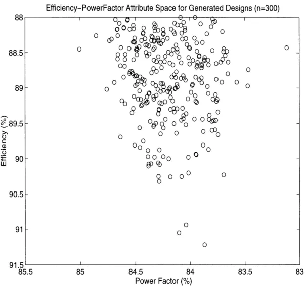
3-5 A 2D View (Efficiency-PowerFactor) of the Attribute Space . . . 3-6 Hit Ratio for Every Iteration . ...
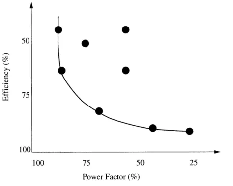
4-1 The Pareto Optimal Frontier . ... 4-2 The Trade-Off Method...
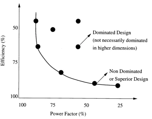
4-3 The Dominant Frontier in 2D Attribute Space ... 4-4 Classification and Regression Trees ...
4-5 MARS Schematic ...
4-6 A Sample MARS Surface Fit . ... 4-7 Limitations of our Proposed Methodology ...
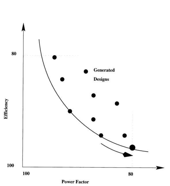
4-8 A 2D View of the 4D Attribute Space with Optimized Designs . 4-9 Efficiency Improvement for Every Starting Point ...
5-1 5-2 5-3 5-4 5-5 5-6 5-7 5-8 5-9 5-10 5-11
The Different Modules of the NDA . . . . Cutaway View of a Single Phase Induction Motor. Inc. Advanced Development Center, St. Louis) . . . Stator Lamination Schematic . . . .. Rotor Lamination Schematic . . . . . .... The Initial Screen of the NDA . . . . The Attribute Screen of the NDA . . . .. The First Input Screen of the NDA . . . . The First Input Screen of the NDA - II . . . . The First Input Screen of the NDA - III . . . . The Second Input Screen of the NDA . . . . Design Sub-Space Identification Complete . . . .
(Courtesy: Magne Tek 100 103 105 106 109 111 112 114 115 116 117
5-12 One (Sample) Generated Design ... .... . . 118
5-13 Attribute to be Optimized ... ... 119
5-14 The Optimized Design ... ... ... . 121
5-15 Evaluation of Optimized Design . ... ... 122
5-16 The Starting Point which produces the Optimum Efficiency ... . 123
List of Tables
1.1 3Hp 4Pole 460V Example . . . . PolyPhase Solver - Attributes and Design Variables.. Rule Sets for the PolyPhase Solver . . . . SinglePhase Solver - Attributes and Design Variables. Rule Sets for the SinglePhase Solver . . . . Generator Solver - Attributes and Design Variables.. Rule Sets for the Generator Solver . . . .. MIT 3Phase Solver - Attributes and Design Variables. Rule Sets for the MIT 3Phase Solver . . . ..
... . 125 ... . 126 . . . . 127 . . . . 127 . . . . 128 ... . 129 . . . . 129 . . . . 130
Two PolyPhase Motors Considered . . . . Three Examples for the P1 Motor . . . . P1 Efficiency Runs ... ... P1 BreakdownTorque Runs ... Three Examples for the P2 Motor . . . . P2 Efficiency Runs ... P2 BreakdownTorque Runs . . . .. Two SinglePhase Motors Considered . . . . Three Examples for SinglePhase Motors . . . . S1 Efficiency Runs ... S1 BreakdownTorque Runs . . . .. S2 Efficiency Runs ... S2 BreakdownTorque Runs ... The Generator Experiment Considered . . . . . Three Examples for Generators . . . . G1 Efficiency Runs ... G1 Field Current Runs ... ... 211 Factorial Experiment for the P1 motor . . . 211 Factorial Experiment for the P2 motor . . . Sensitivity Analysis for optimized P1 motors Sensitivity Analysis for optimized P2 motors Regression Data for Motors Similar to P1 . . . Regression Data for Motors Similar to P2 . . . . . . . . . 134 . . . . . 135 . . . . . . . . .. . 135 . . . . 136 . . . . . . . . . 137 . . . .. . 137 . . . . . . . . . 138 . . . . . 139 . . . . . . . . . . 140 . . . . . . . . 140 . . . . . . . . . . . 140 . . . .. . 14 1 . . . . . . . . 14 1 . . . . . 142 . . . . . . . . . 143 . . . . . . 143 . . . . . .. . 143 . . . . . 148 . . . . . . . . . . . 149 . . . . . 152 . . . . . 153 . . . . . . . . . 156 . . . . . . . . 157 5.1 5.2 5.3 5.4 5.5 5.6 5.7 5.8 6.1 6.2 6.3 6.4 6.5 6.6 6.7 6.8 6.9 6.10 6.11 6.12 6.13 6.14 6.15 6.16 6.17 6.18 6.19 6.20 6.21 6.22 6.23 29
6.24 Costs and Payback Periods for PIE and P2E series designs . ... 160 6.25 Manufacturing Costs and Order Sizes for PIE & P2E Experiments .... . 162
Chapter 1
Introduction
1.1
Motivation for the Project
Industry today is faced with a variety of challenges in a fast changing world. Competitive pressures have forced companies to reduce the time to market their products, react fast to customer requirements, innovate continuously, and tailor their products to add value for customers. Firms today are expected to deliver high quality, low cost, innovative products with extremely short development lead times. Rapidly changing technology has also sig-nificantly changed the way businesses are managed. Careful attention has to be paid to managing information and enhancing information flow. All resources at the disposal of the firm have to be put to optimum use to reach these goals. All existing development processes have to be improved, and optimized to enhance productivity.
This thesis concentrates on automating the process of design in a product development environment. While the individual recipes for success vary by product type and the specific industry involved, the basic ideas remain the same for many engineering artifacts. For the purposes of this thesis, we will concentrate on the electrical motors and generators indus-try. We will develop a design automation tool for designing motors which can reduce the development lead time, and can lead to improved decision making during the development process.
16 Chapter 1. Introduction MANUFACTURING PROCESS Exper Resul Design Manufacturing Proposal Capability
Product Requirement THE Question "
CUSTOMER ENGINEER DESIGN DATABASE
SPROCESS
PossiblLduct Possibilities A n s w er
Theoi Resul
Figure 1-1: The Development Process
retical ts
1.1.1
The Development Process
Broadly speaking, manufacturing processes may be classified into three categories: mass production, batch manufacturing, and job-shop manufacturing [95]. Mass production is typically characterized by large product volumes, steady (high) demand, low product varia-tion, and expensive assembly lines. Batch Manufacturing handles medium product volumes, with volatile demand, and high product variation. Job-shop manufacturing is typically for extremely low product volumes, expensive products (e.g. a ship), and extremely high prod-uct variation. Most electrical motors (especially smaller ones - used in appliances), are mass produced, with relatively large product volumes and expensive assembly lines. How-ever, motor manufacturing in general, also retains features of batch manufacturing, like
high product variation and differentiation, and changing demand patterns.
The development process for such an industry may be viewed as shown in Figure 1-1 [72]. Moving from left to right in the figure, the customer comes in to the firm with a set of requirements and specifications. He meets with the engineer who is his contact point in the firm. The engineer then examines the feasibility of the project. He takes the requirements
imental ts
1.1. Motivation for the Project 17
through a "design process". The first step is to query the database which may be anything from a group of designers in the design division, with expert knowledge and a lot of expe-rience, to an electronic database of all data. Using this information, the engineer comes up with a few designs which might meet the customer's specifications. During this process, frequent consultations might also be required with the manufacturing process engineers. The engineer then returns to the customer with a list of possibilities. The customer reviews the specifications and may suggest changes or enhancements. If changes are required, the design process goes through another iteration. Finally, the customer chooses a design that he is satisfied with, and places an order for manufacturing the product. Sometimes, the design process would go through many iterations before an order is placed. The subsequent series of events is straightforward (not shown in the figure). The specifications are sent to the manufacturing unit and the product is made and delivered to the customer.
1.1.2
Automating the Development Process
The entire "design process" shown in Figure 1-1 usually takes a few weeks from start to finish. Clearly, the design process is one of the important processes contributing to the development lead time. If it were possible to automate this process while retaining all the earlier benefits and flexibility, the lead time would be reduced tremendously [96]. There is evidence that at least one firm has benefited from this approach [33].
There are a number of potential areas where automation would speed-up the design process:
* Database: The design process involves frequent consultations with the database. This process can be made faster by consolidating the firm's experience into an electronic database. The designers have some expert knowledge which is very valuable to the firm, and which might be lost when employee turnover occurs. Storing this knowledge electronically, and making it accessible for all designers, would organize the learning process over the course of many development programs. Keeping all design data electronically also has innumerable advantages, especially if computer programs can access and query this database.
18 Chapter 1. Introduction
* Models: Building physical and manufacturing realities into mathematical models which can be evaluated using a computer would also enhance the efficacy of the design process. In the motor industry, such mathematical models typically take the form of circuit models for evaluating motor design characteristics and performance. Other possible models could include heat-transfer models, simulations of processes, models for manufacturing tolerances etc.
* The Design Process: Besides the electronic database and computer models, it is the design process itself which requires many iterative procedures, and relies a lot on the designer's expertise and intuition. Coupled with an electronic database and computer models, automating this process would have many potential advantages. Since com-puters can be used to perform this task, the most obvious gain is the speed at which the process can be completed. In addition, multiple alternatives can now be eval-uated, which would improve the quality of the design process, often with favorable cost impacts. Various optimizations would also follow as a logical extension to this scheme.
* Information Flow: Facilitating better information flow between the parties involved is very critical for improving process efficiency. Many times, all the information might not be available at one physical location. The advantage of electronic communication cannot be over-emphasized in this context.
1.1.3 Summary of Goals for the Project
The goal of this project is to develop a computer based tool for automating this highly interactive and time-consuming process of design. The methodology used for this tool would be fairly generalizable for other industries and engineering artifacts. Specifically, this tool would attempt to accomplish the following objectives:
* React fast to customer requests. Once a customer comes in with a set of requirements, the designer should be able to respond to the customer's requests faster.
1.2. Project Organization and Background 19
* Improve the development lead time. Reduce the total time it takes to converge on the best design possible and send it over for manufacturing.
* Facilitate multiple scenario analysis. Evaluating multiple scenarios would help im-prove the quality of decision making, with possible cost impacts. This in turn would add value for the customer. One of the ideas implicit in multiple scenario analy-sis is that the options or scenarios considered should be fairly "new" or "novel" for maximum customer impact.
* Offer better optimization capabilities. This would help with decision making and would also help understand the trade-offs involved in meeting customer demands.
1.2
Project Organization and Background
This project has been named as The Novice Design Assistant Project and the resulting system is called the NDA (Novice Design Assistant). The term "novice" is chosen since the system starts like a true novice with limited knowledge and ends up with new designs and some knowledge about the design parameters (this will be discussed in detail in later chapters).
The project was initially started as an intellectual exercise in building design assistants and over the years has resulted in a viable package which, it is hoped, would be useful to the industry.
1.2.1 Project Background
This project was started in 1989, as a collaborative effort of Professors Lang, Tabors, and Kirtley, at the Laboratory for Electromagnetic and Electronic Systems, MIT. The initial work was supported by the Leaders for Manufacturing Program. Professor James L. Kirtley Jr. wrote an analysis module for analysis of an induction motor. James A. Moses worked on the NDA and built a design assistant with a prototype database together with its database management routines and a preliminary synthesis module. This work is reported in his Master's thesis [72] and in a conference article [73]. Studies on a manufacturing simulator
20 Chapter 1. Introduction
and a costing module were done by Christopher L. Tucci and are described in his Master's thesis [111] and in a conference article [112].
The design synthesis ideas of the NDA were developed by the author and are reported in his Master's Thesis [96] and a conference article [97].
This thesis picks up on the previous work and enhances the features and capabilities of the NDA. The design synthesis concepts are formalized and tested with industrial strength examples. The design synthesis modules are augmented with appropriate multi-objective optimization ideas. All proposed ideas are tested on industrial examples and with different kinds of electric machines and (circuit equation) analysis routines.
1.2.2 Objective
The objective of the NDA project is to develop a software design tool which meets the goals outlined in Section 1.1.3. Such a design tool could be schematically represented as shown in Figure 1-2. The user would specify a set of performance requirements e.g. Efficiency, Power Factor etc., together with a set of (optional) constraints e.g. Stack Length not to exceed (say) 10cm. The system would then process this information and generate a set of designs which would meet the specified set of performance requirements.
For the purposes of this thesis, we define two terms to characterize the two kinds of inputs required from the user. Design Parameters and Performance Parameters. Design
Parameters are the variables used for building up the motor. Examples are air gap, number
of turns, and slot width. The customer typically is not interested in the exact values of these variables directly. However, he/she may frequently specify bounds on the values of these variables as constraints e.g. Stack Length not to exceed (say) 10cm. Performance
Parameters, also referred to as Attributes, characterize a motor's performance. Examples
include efficiency, power factor, breakdown torque, core volume or mass. The customer is usually interested in evaluating and characterizing a motor design based on these parame-ters, and specifies them as "Requirements". In addition, these attributes always have to be maximized or minimized for an ideal design. These variables are typically computed using electrical models, and most or all of the design parameters are needed for their computation.
1.2. Project Organization and Background
DESIGN
USER SYSTEM
Constraints
Solutions to the User
Figure 1-2: Software Design Tool for Induction Motors
1.2.3 Salient Features of Software System
The software system described above attempts to automate the design process and its various interactions as described in Section 1.1.2. The salient features of the system include:
* Automation of the Design Process. The user can specify requirements and con-straints, and the NDA goes through a set of design procedures, and generates a list of designs which meet those demands. (In case, some of the requirements are infeasible or difficult to attain, the NDA relaxes some attributes suitably. This will be discussed in Chapter 3).
*
Optimization. The user can then review the designs and choose to optimize based on any one attribute. The other attributes are still retained within the limits specified earlier. e.g. After reviewing the designs generated, the user can choose to optimize for efficiency while maintaining all his earlier requirements and constraints.* Mathematical Models. In order to evaluate any given motor design, the system requires the necessary mathematical models. These models, which will be different for every kind of machine, need to be integrated into the NDA system. These models
22 Chapter 1. Introduction
are referred to as solvers in the rest of this thesis. The completed NDA has four kinds of solvers: PolyPhase solver for evaluating polyphase induction motors, SinglePhase solver for single phase induction motors, Generator solver for generators, and a 3Phase solver for simple 3 phase squirrel cage induction motors. These will be described in
Chapter 5. Their sources are discussed below in Section 1.2.4.
*
Electronic Database. The NDA communicates with a state-of-the-art electronic database which contains production design data for motors and their supporting parts e.g. slot geometries, laminations, end rings etc. The solvers communicate with the database on a regular basis to retrieve part specifications. In addition, the user can also interact with the database to store, retrieve, or view any information.1.2.4 Relationship with Industry
For the past 5 years, the project has been supported by MagneTek Inc., and the NDA has been developed in partnership with the Advanced Development Center (Motors and Generators Division) of MagneTek in St. Louis. From 1989-1993, when the project was supported by other agencies, the NDA was designed as a fairly general system. During the association with MagneTek, the NDA was customized and specialized to work in their design environment. Consequently, the NDA is now a powerful tool for use in an industrial setting. However, it is still fairly general and extensible. Adding more solvers for different kinds of machines is fairly straightforward. The methodology, of course, remains extremely general and should be applicable to a large number of engineering artifacts.
For success in MagneTek's design environment, the NDA had to integrate MagneTek's solvers and communicate with MagneTek's database. Three out of the four solvers (PolyPhase, SinglePhase and Generator) were supplied by MagneTek. These solvers have been used ex-tensively by the company for evaluating designs. The same solvers are accessed by the NDA to help analyze designs, and compute performance. The fourth solver (3 Phase solver) is a relatively simple solver developed at MIT. It is simply another version of the original evaluator written by Professor Kirtley in 1989.
cus-1.2. Project Organization and Background
tomizes the NDA user interface and output formats for use within MagneTek.
For proprietary reasons, information pertaining to MagneTek's solvers and database cannot be presented in this thesis. Hence, all examples presented in Chapter 6 and elsewhere present only an overview picture and relevance of the results. No actual designs are discussed or presented.
1.2.5 Issues Addressed in this Thesis
Section 1.2.3 presented four salient features of the NDA system. Two of these (mathematical models and database) are provided to us by MagneTek. The other two aspects, design process automation and optimization form the crux of this thesis. These are described in
Chapter 3 and Chapter 4 respectively.
This thesis is devoted to developing a software tool for designing motors as outlined above in Section 1.2.2. The tool has been developed in its entirety including the methodology and an industrial strength software implementation. The tool endeavors to meet all the goals described in Section 1.1.3.
1.2.6 Case Study Implementation
The methodology developed in this project is intended to be very general and suitable for a wide class of problems. The aim of the project is to develop a design methodology which can be used for a variety of applications. Induction motors and generators were chosen as a case study for this project since these machines are examples of mature, well-understood technology [72]. There is evidence [33] that at least one firm has been successful in this market by the rapid-turnaround of motor designs to fulfill their customer's special needs.
For the general methodology to be applicable to other engineering artifacts, two require-ments need to be met from the problem:
1. All variables of interest should be clearly defined with their minimum and maximum limits, and step-sizes if applicable. These variables should be clearly divided into design parameters and attributes.
24 Chapter 1. Introduction
2. An evaluator or analysis routine must exist to compute the performance parameters given a complete set of design variables. Another practical consideration relates to the running time for the evaluator. For our methodology, the evaluator is invoked a very large number of times. Consequently, FEM based evaluators may not be suitable for our methodology given present day computer speeds.
Once these assumptions are satisfied, the methodology presented in this thesis should be applicable to other areas and examples.
1.3
Literature Review and Critical Analysis
Since the issues addressed in this thesis are very diverse, each chapter, as it deals with a particular topic, presents more of the literature survey and deals with some of them in greater depth. Here, we will be discussing the literature which deals with the general methodology and the philosophy of design assistants. A lot of the literature review may also be found in Chapter 2.
Various schemes have been suggested in literature for the automation of design processes. But the usual drawback with almost all of these is that these systems are very weak when
it comes to synthesizing new designs.
Another important aspect tackled in this thesis is optimization. There is truly no dearth of literature related to optimization. However, there are very few optimization techniques which handle complex cases like electric machine design (refer Chapter 2).
Articles found in literature relating to design and design assistants may be classified into three categories: design optimization, expert systems, and other techniques. [6] gives a much broader overview of the methodologies used in mechanical design automation. For our purposes here, it will suffice to talk about the three categories mentioned above. We
will also briefly discuss some literature pertaining to electric machines.
[11] refers to an optimization procedure which has been successfully applied to conven-tional optimization problems. [20] and [21] describe an optimization procedure that is based on searching the entire design space. This will be examined in some detail in Chapter 2.
1.3. Literature Review and Critical Analysis 25 Another approach in design optimization is to evaluate and redesign rather than create a design from first principles [51]. The idea is to modify a design till it conforms to all requirements and constraints. Another such example is found in [16] which employs the same technique but uses expert systems for this purpose. Moses [72] also cites a number of references which deal with non-linear optimization as a means to optimize the design of induction motors. The most general problem with optimization is that optimizing can be costly and deals with only one objective [28]. Optimizing for more than one objective at a time, is often impossible. Moreover, complex, good real designs seldom optimize a single objective; rather, they trade off performance among their various objectives. Single valued optimization does not offer much flexibility to respond to real customer preferences. Techniques for multi-objective optimization will be detailed in Chapter 4.
Recently, two techniques have emerged from the Artificial Intelligence community which offer global optimization capabilities. These are: Simulated Annealing [113] and Genetic Algorithms [47]. Simulated Annealing is based on the concept of annealing of solids and is based on the Metropolis algorithm [71]. Kirkpatrick et al [57] modified the algorithm to solve combinatorial optimization problems. Extensions to continuous variables followed immediately [114]. Genetic algorithms represent ideas inspired by natural evolution [120]. A lot of literature may be found which deals with these approaches and their applications. [22] is one such collection of papers. Both of these methods, however, require experience in fine tuning their parameters. [118] discusses an excellent design methodology which uses Genetic Algorithms for optimization. Some additional literature related to these topics is discussed in Chapter 2.
Expert Systems are used extensively for all kinds of design and synthesis work. But they lack the real flavor of innovative synthesis in them. However, they constitute a bulk of the research work in computer assisted design. [87] gives a very good outline on the use of expert systems in engineering design. A selective bibliography is also given. [83], [25], [68], [105] and [32] are excellent examples of research done in the area of Expert Systems in design. [25] also deals with optimally searching the space but uses a lot of heuristic knowledge about the problem. [83] tackles issues in interfacing expert systems with design
26 Chapter 1. Introduction
databases. [105] introduces expert systems which constrain design. There are two problems with using expert systems for synthesis. The traditional expert system attempts to mimic the designer's conception of the problem, building the designer's prejudices into the software. Secondly, the expert system only deals with a part of the design space that has already been explored and information about it stored as a part of the domain knowledge embodied in the expert system. There is very little scope of "creativity" per se in design. [9] and [63] outline some of the attempts to tackle this using fuzzy logic. [62] gives some background about fuzzy logic.
Expert Systems for architectural applications form an interesting class of examples. [54] models architectural design as a search process in a space of alternative solutions. [80] presents an approach to generative expert systems for architectural detailing based on design grammars and knowledge engineering. [85] is another interesting application: using design codes as expert systems. [86] and [78] are later articles from the same research group as above and very clearly distinguish between the concepts of design analysis and design synthesis. They view design as a goal oriented activity and use expert systems for both analysis and synthesis. Such an integrated approach requires the implementation of both generative and evaluative rules at different design levels within the same knowledge base. This is a powerful procedure but suffers from the same problems of lack of real "creativity". It should be pointed out however, that this approach is much more useful for architectural applications where rigorous quantitative reasoning and analysis are not encountered very frequently.
Artificial Intelligence (AI) techniques try to tackle this problem also. A lot of AI re-search is related to conceptual geometric design of mechanical elements. [27] deals with a design invention system which considers three general strategies for creating novel devices: generalization, analogy and mutation, all of which rely on memory organization, indexing and retrieval. [6] outlines another example which applies analogical problem solving to me-chanical design. The constraint model for designing is used in [99] and [28]. [99] generates a solution tree of alternatives by processing through the static knowledge hierarchy and synthesis constraints are used to prune the solution tree. [46] and [26] give useful
bibli-1.4. Thesis Overview 27
ographies of books and articles relating to artificial intelligence and expert systems in the area of design. Most of the techniques outlined here help design simple systems which are categorized qualitatively. For our applications, we already have the qualitative knowledge about the design of induction motors. We are more interested in new designs which have better performance. Our demands are much more specific.
Another interesting approach to design is presented by Nam P. Suh [101], [102], [103], [104]. This approach is called Axiomatic Design. The key concepts of axiomatic design are: "the existence of domains, the characteristic vectors within the domains that can be decomposed into hierarchies through zigzagging between the domains, and the design axioms (i.e. the Independence Axiom and the Information Axiom). Based on the two design axioms, corollaries and theorems can be stated or derived for simple systems, large systems, and organizations" [102].
Specifically, there has been very little published work on computer based design tools for electric motors [72]. This, in fact, is a part of our motivation for the NDA project. One book [116] deals with this topic in some depth. It proposes several synthesis procedures which are essentially rule based, and it describes a computerized sales order specification system used in industry. This system concentrates on providing solutions to customer requests, but has limited synthesis possibilities. [61] outlines an Expert System for the Design of 3-Phase squirrel cage induction motors. Moses et al. [73] refer to other computer design tools described in [60] and [17]. [3] describes a general design synthesis and optimization procedure based on the Monte Carlo paradigm.
1.4
Thesis Overview
Before we begin a detailed description of the methodologies used and our implementation, let us outline the salient features of the thesis and present a sample result.
In order to develop the "system" depicted in Figure 1-2, we have developed a two step methodology.
In the first step, we generate 200 designs which match the user's requirements. The motivating idea behind this step is to identify a "good" region in design space which is most
Chapter 1. Introduction
likely to contain designs matching the user's given requirements. We use a Monte Carlo based design technique which uses means and standard deviations of gaussian populations to steer the random number generation process.
In the second step of our methodology, we optimize designs based on any specified design parameter while keeping all other requirements within user specified limits. This is achieved using a non-linear programming optimization algorithm. Since our space is not well characterized, we use a function approximation tool called MARS (Multivariate Adaptive Regression Splines) to obtain a surface map of the functional relationship between an attribute (requirement) and all the design (explanatory) variables. This surface map helps us compute the function values and gradients at all locations in the multi-dimensional space (and not just the 200 points generated in the first step).
These ideas are implemented in a software system which functions with four different circuit equation solvers. The four solvers are for polyphase motors, singlephase motors, generators, and a simple solver for a 3phase motor. The first three are industrial solvers and have been supplied by our corporate sponsors. The last solver is an academic example which has been developed by Professor Kirtley at MIT. Our software system has an X-Motif user interface. The entire system runs on HP9000 workstations.
We have tested our system against a number of real life industrial examples and this set of results has been very promising. We present one such experiment here, to show an example of our results. This sample run is for a 3Hp, 4 pole, 460V, 60 Hz, 3 phase induction motor. An existing industrial design with these specifications has an efficiency of 85.9%. We choose to modify and improve this design using our system. A total of three runs were performed with identical target requirements. The constraints were progressively relaxed for these three runs. In the first run (A), we allow the slot geometries and winding parameters to vary. In the second run (B), we allow the end ring to vary in addition to the variables in A. In the final run, we allow some critical geometric parameters like stator inner diameter and rotor outer diameter to vary in addition to all variables in B. A summary of our results is presented in Table 1.1. The "BaseEff" column reports the efficiency of the existing industrial design. The "Best Generated" column presents the best efficiency result from the first step
1.5. Thesis Organization and Road Map 29
Table 1.1: 3Hp 4Pole 460V Example
of our methodology. The "Best Optimized" column presents the best efficiency design from the second step of our methodology. The average efficiency improvement between the first and second steps is shown in the "AveImpr" column.
The improvements suggested in Table 1.1 are significant. We will present additional examples, results, and analyses in Chapter 6.
We hope the NDA would be a viable design tool in industry and we look forward to gathering a lot of collective industrial experience with our methodologies and software system.
1.5
Thesis Organization and Road Map
Every chapter addresses a specific topic and begins with a brief description of the previous work done on that topic and in that field in general. Problem formulation and related literature survey are tackled in Chapter 2. The issues tackled in this thesis have been divided into four modules for the purposes of the NDA. The first module is presented in Chapter 3, and deals with identifying a relevant region in the design space which is likely to meet the user's requirements. This is the primary module for automating the design process. The second module deals with optimization. These issues are detailed in Chapter 4. The third module deals with the aspects of integrating different solvers in the NDA. The fourth module was the user interface for the NDA. The third and fourth modules are presented in Chapter 5. Chapter 6 presents the results obtained by running the NDA, and analyzes
Run BaseEff Best Best AveImpr
ID (%) Generated Optimized (%)
A 85.9% 87.6% 87.8% 0.5%
B 85.9% 88.0% 88.0% 0.5%
30 Chapter 1. Introduction
those results. The thesis concludes with Chapter 7 which summarizes the thesis and presents directions for future research.
Chapter 2
Problem Formulation, Alternative
Approaches and Proposed
Methodology
As outlined in Section 1.2.2, the objective is to design a software design tool where the user can specify Requirements and Constraints and completed designs are returned to the user. In this chapter, we discuss how we break down this rather abstract problem into manageable pieces. Section 2.1 deals with the problem formulation i.e. how we think about the problem and the framework we lay down for solving it. In Section 2.2 and Section 2.3, we present some techniques for solving the presented problem. Section 2.4 outlines our proposed methodology which will be examined in detail in the following chapters.
2.1
Problem Formulation
2.1.1 Modules of the NDA
As mentioned in Section 1.2.3, the NDA has four parts together with a user interface. The user submits requirements and constraints using the User Interface. This information is then sent to the Design Automation (or Design Synthesis) module. The Design Synthesis
32 Chapter 2. Problem Formulation, Alternative Approaches and Proposed Methodology
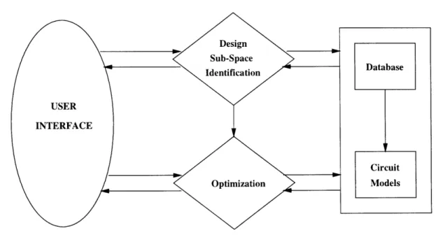
module generates a few designs while using information from the Database and Circuit Models (Solvers). After the design generation phase, the generated designs are sent back to the user, who may decide to proceed with optimization. The Optimization module uses information from the Database and Circuit Models, and the Design Synthesis module. The optimized design is again sent back to the user interface. In this simple operation process of the NDA, Design Synthesis necessarily precedes Optimization and the user interface ensures that things happen in a logical sequence. The Modules of the NDA are schematically shown in Figure 2-1.
Figure 2-1: The Different Modules of the NDA
In the following Sections, we will discuss how we formulate the problem of Design Syn-thesis and how the design process is modeled in the Design SynSyn-thesis module. The Op-timization module follows from pretty much the same problem formulation, but differs in content and function. The Optimization module is described in Chapter 4.
2.1. Problem Formulation 33
2.1.2
The Design Process
"Design" may be considered to be of three types or levels [86]. The first and most difficult is the design of an artifact to satisfy a set of goals when even the general form of the artifact is not known. Let us say we do not know that a household washing machine exists. The top level of design would deal with the problem of inventing a machine or a concept which would be useful for washing clothes conveniently. The second level of design deals with the problem of deciding design parameters when the general form of the artifact is known. This is one of the common "hard problems" in engineering. In the washing machine example, this problem would correspond to a scenario where we know the general form and function of a regular washing machine, and the problem is to design a machine which would meet our specific requirements. At the bottom level of design is the process of classification and selecting from a set of fully or partially described solutions. This is similar to selecting the best washing machine available in the market, or from a catalog.
The first level design problems are tackled by some artificial intelligence techniques. References for some AI techniques have been presented in Section 1.3. We do not deal with this class of problems in this thesis.
The third level of design was tackled in a previous work on this project [96], where a database was designed to facilitate easy lookup and storage of motor designs. Another common example of the third level of design is bearing selection [32]. This level of design is also not specifically addressed in this thesis. The concepts have been demonstrated earlier [96], and for the purposes of this project, database lookup and other database interactions are accomplished using in-house software tools and facilities developed by our industrial sponsors.
In this thesis, we focus only on the second level of design. Typically, in such problems, the issue is to generate a design which would match certain performance requirements.
2.1.3 Design Synthesis
Design Synthesis (in our context) is the process of generating a new design starting from certain performance requirements. This is in contrast to the process of analysis where
34 Chapter 2. Problem Formulation, Alternative Approaches and Proposed Methodology
performance is calculated starting from a given design. Usually in engineering practice, and indeed in the area of Electric Machine design, the analysis process is much better understood. The performance calculation equations, and all interrelationships are well established. The process of Synthesis, on the other hand, is much harder. It is also the more common operation in industry. Traditionally, synthesis has been attempted by designers using their insight and experience. This experience is in the form of certain non-formalized "thumb rules" and guidelines. Designers develop intuition about the logical outcome of making certain changes to some of the design variables. This accumulated experience and intuition helps the designers in their designing process, which in essence, is a systematic and organized trial and error process.
Analysis
Synthesis
Design Variable Space (D)
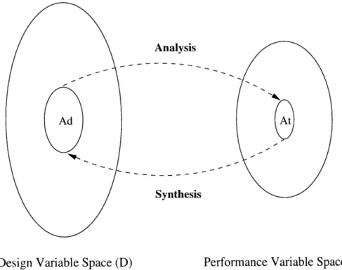
Performance Variable Space (P)Figure 2-2: The Design Process - Variables in Design and Performance Space
This difficulty in synthesizing designs can be better explained using the concept of mapping. Let us define a design variable space D representing the possible values that each of the design variables can assume. Similarly, P is the performance variable space
2.1. Problem Formulation 35
representing the possible values of the performance variables. The process of Analysis is then defined as a mapping from the design variable space to the performance space. This is the forward map. Synthesis is the backward map or an inverse mapping from the performance space back to the design variable space. Given an acceptable target region in the system characteristics space, At, the problem is to find a corresponding acceptable region Ad in the design variable space. This is shown in Figure 2-2 [81]. It is this backward map which is difficult to achieve in a straightforward manner, primarily owing to non-linearities in the mapping.
Let us denote our set of design variables by an n x 1 vector.
S= [X, ...x] T where
x
ED (2.1)and our set of performance variables by an m x 1 vector.
Y = [y, ...yn]T where yeP
(2.2)
The forward map from D to P is then defined as a function from D to P.
y = f(x) (2.3)
and the backward map is defined as the inverse function.
x = f-(y) or x = g(y) (2.4)
2.1.4
Important Issues Involved
For our problem of electric machine design, it is this inverse map g or f-1 which is nearly impossible to obtain. Equation 2.3 is so involved that it is extremely difficult to write it explicitly. Writing Equation 2.4 is out of question. We can identify six primary reasons why the process of synthesis is so hard for our problem:
36 Chapter 2. Problem Formulation, Alternative Approaches and Proposed Methodology
* Non-linearities. The mapping f is highly non-linear. Many techniques exist for
manipulating linear equations, but there are relatively few techniques for managing non-linearities elegantly.
* Coupled Equations. The equations in Equation 2.3 are highly coupled. In most
solvers, some iterative procedures are used to arrive at certain intermediate quantities (e.g. slip in an induction motor).
* Discrete and Categorical Variables. Some variables xi of Eq 2.1 are discrete in
nature. Examples include Number of Turns of Wire in a slot. There are some others which are purely categorical (i.e. cannot be ordered) e.g. material for stator and rotor iron. Most mathematical techniques handle only continuous variables. The few techniques which handle categorical variables are not as powerful or general.
* Dimensionality. We are dealing with a large number of variables which adds to the
complexity of the problem. The number of possible combinations of these variables grows exponentially with the number of variables.
* Multiple Objectives. Our performance variable space is multi-dimensional i.e. we
deal with a number of attributes concurrently. For example, for a polyphase design, we are interested in Efficiency, Power Factor, Breakdown Torque, Locked Rotor Torque, Locked Rotor Current, Slot Fill, and Core Volume. Most mathematical techniques (especially optimization techniques and non-linear techniques) deal with only a single attribute.
* Under-Constrained Problem. The dimensionality of the design space is much
higher than the dimensionality of the performance space.
Another important issue which merits attention at this point is the relative speed of the design analysis and synthesis operations. Usually, analysis processes are better understood and formulated, for most engineering artifacts. For example, for electric motors, we have circuit models which help us compute the performance of a given design. Consequently, this process is relatively faster. Synthesis, on the other hand, is not so conveniently performed.
2.2. Alternative Approaches found in Literature 37 Many synthesis techniques apply analysis routines multiple times to perform the synthesis operation. As a result, synthesis is usually slower. This has important implications espe-cially for cases where the analysis is not fast e.g. FEM models. Synthesis in such scenarios is even harder, much slower, and perhaps less accurate. For the purposes of this thesis, we will not consider such cases since our analysis routines take on the order of 5-10 seconds to run. However, in Section 4.2 we will introduce a function approximation technique which can be used to circumvent this problem, should it arise in other research contexts.
2.2
Alternative Approaches found in Literature
The problem formulated in Section 2.1 is a common problem encountered in engineering analysis and different researchers have used different simplifying assumptions and techniques to circumvent its inherent difficulties. Most of the ideas described below may be found in the author's Master's thesis [96]. Some related work has also been presented in Section 1.3. Consequently, the discussion here will be brief. We mention these techniques here for the sake of completeness.
2.2.1 Expert Systems
Expert Systems embody a core of knowledge about a (very) specific field. This knowledge is compiled by a body of experts and captures the "experience" of the experts. Usually, knowledge in expert systems takes the form of "if ... then ... " rules. Hence expert systems are ideally suited for the third level of design. With this class of problems, the goal driven or backward chaining process of Expert Systems can be used to accomplish all design goals. Expert Systems have also been used for the second level of design by trying previously known solutions. Good discussions may be found in [78] and [86].
Expert Systems are unsuitable for the NDA since they lack the flavor of real "creativity" in synthesizing solutions. The NDA is intended to be useful for designers who are looking for novel and innovative designs, usually something they have not encountered before.
38 Chapter 2. Problem Formulation, Alternative Approaches and Proposed Methodology
2.2.2
Grid Search
Another popular technique is to search all possible solution states i.e. search the entire (n-dimensional) grid of solution states in the design variable space. Usually, as the number of design variables gets large, this brute force approach becomes computationally prohibitive. It is useful and satisfactory for simple problems where the number of design variables is small and the number of grid-points (on every design axis) is fairly small. Nevertheless, techniques based on the grid search have been very popular. Most of them attempt to avoid searching the entire grid. They search only a part of the grid and arrive at an acceptable solution. There is an interesting application where concepts of Knowledge Engineering and Expert Systems are combined with grid search to develop a powerful (application specific) design methodology for design optimization [20] and [21]. Grid search ideas have also been used for optimization [11].
Our solution space is extremely large (has high dimensionality) and this technique is therefore ruled out. The NDA problem does not satisfy other requirements of [20] either which eliminates the possibility of combining grid search with knowledge engineering.
2.2.3
Linearizing the Mapping
Many researchers have approached the above defined problem by attempting to linearize the mapping about a nominal design point. Rai [81] has proposed a Singular Value De-composition based approach which has been very successful with robot design examples. This method assumes that the designer has a nominal design as the starting point. This starting design meets the basic requirements of the designer. Starting from this nominal design point, the space in close proximity of this point is linearized, and preferred directions for maximizing the sub-goal in performance (for that step) are computed.
This approach has the attractive property that multiple objectives can be very conve-niently handled. However, it is still unsuitable for the NDA since our space is very highly non-linear. A lot of information will be lost in the linearization process and may lead to erroneous results. We also want to avoid specifying a feasible design a priori, which would