Design and Manufacture of an Ultra-High Field
Ex Vivo Coil Assembly
by
Loren Daniel Bridgers
B.S. Mechanical Engineering
University of New Mexico, 2010
Submitted to the Department of Mechanical Engineering
in Partial Fulfillment of the Requirements for the Degree of
ARCHIVES
Master of Science in Mechanical Engineering
MASSACHUSETTS INSTITUTEOF TECHNOLOGY
at the
I
JUN
28
2012
MASSACHUSETTS INSTITUTE OF TECHNOLOGY
LIBRA RIES
June 2012
D 2012 Massachusetts Institute of Technology. All rights reserved.
A uth or
...
...
. ...Department of Mechanical Engineering
May 18, 2012
C ertified by ...
...
Alexander Slocum
Pappalardo Professerf Mechanical Engineering
,/ -. A Te@)upery.srA ccepted by...
...
Professor David E. Hardt
Professor of Mechanical Engineering
Chairman, ME Committee for Graduate Students
Design and Manufacture of an Ultra-High Field
Ex Vivo Coil Assembly
by
Loren Daniel Bridgers
Submitted to the Department of Mechanical Engineering on May 18, 2012
in Partial Fulfillment of the Requirements for the Degree of
Master of Science in Mechanical Engineering
Abstract
Magnetic Resonance based architectonic segmentation aims to detect variations in brain
architecture that may provide incredible insight into diseases such as epilepsy,
schizophrenia, dyslexia, and autism. Data from ex vivo scans is necessary for the
development of automatic methods to detect these critical variations in vivo (1) (2). The
optimization of ex vivo imaging requires the design and construction of special purpose
instrumentation. This thesis presents the mechanical design and construction of a 32
channel ex vivo coil assembly for use in a 7 tesla MRI. The unit will be used for research
at the Athinoula A. Martinos Center for Biomedical Imaging in Charlestown,
Massachusetts. Also presented is the development and implementation of two unique
low-cost tools to enhance the medical instrument prototyping process: a desktop vacuum
casting system, and an automatic tool-path generation program for machining directly
from STL files. Finally, an improved method and apparatus for degassing the tissue
samples is developed and implemented leading to improvements in MRI image quality.
Contents
Ex-vivo background ... 5
1.1. Ex V ivo M otivation...5
1.2. M RI Fundam entals...6
2. Design of the 7T 32 channel ex vivo coil assem bly ... 11
2.1. Fundam ental Requirem ent Overview ... 11
2.2. Previous Approaches...11
2.2.1. Previous Holder Design... 11
2.2.2. Previous Birdcage Design ... 12
2.2.3. Previous Receive Array Design... 13
2.2.4. Previous Degassing Approach... 13
2.3. The M anufacturing Challenge... 13
2.4. The M anufacturing Solution... 14
2.5. Des ign Overview ... 14
2.6. Detailed Requirem ents and Design Solutions ... 15
Requirem ent 1: Positioning ... 17
Requirem ent 2: Coil Placem ent... 17
Requirem ent 3: Brain Housing...21
Requirem ent 4: Brain Holding ... 22
Requirem ent 5: Integration with Brain Degas Process... 23
2.7. B 1 Transm itting Coil Design, The Birdcage ... 24
2.7.1. Transm itting Coil Function ... 24
2.7.2. Birdcage Design ... 25
2.7.3. M ounting Plate Subassembly ... 31
2.7.4. Planar Geom etries ... 32
3. M anufacturing Processes...33
3.1. Selecting Processes...33
3.2. The Bench-top vacuum casting unit...33
3.2.1. Process Overview ... 33
3.2.2. A dvantages of Vacuum Casting ... 34
3.2.3. Benchm arking ... 36
3.2.4. The Desk Top System Concept ... 36
3.2.5. Degassing the Casting M aterial... 37
3.2.7. The Pinch V alve ... 38
3.2.7.1. Servo Pinch Valve Design...39
3.2.7.2. Cam Design ... 41
3.2.7.3. Lessons Learned / Im provem ents for Rev. 2... 42
3.2.8. Silicone M olds...43
3.2.9. M aking the Silicone M olds ... 45
3.2.10. Casting Process and Results ... 48
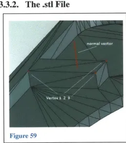
3.2.11. Hybrid M olds ... 50 3.2.12. Flow Analysis...52 3.3. DanCam ... 53 3.3.1. M otivation ... 53 3.3.2. The .stl File...53 3.3.3. Im porting the .stl... ... 54
3.3.4. Finding the plane-line intersects... 54
3.3.5. Tool Offset...56
3.4. Calculating Cutting forces and m achine requirem ents... 58
4. M anufacturing The 32 Channel Ex-vivo Scanning A ssem bly ... 62
4.1. Inner Brain Holder...62
4.2. Receiving coil form er...62
4.3. M ounting Plate...62
4.4. The Bird Cage ... 63
4.5. Reducing therm al stress during soldering ... 65
5. Brain Degasing...69
5.1. The Problem ... 69
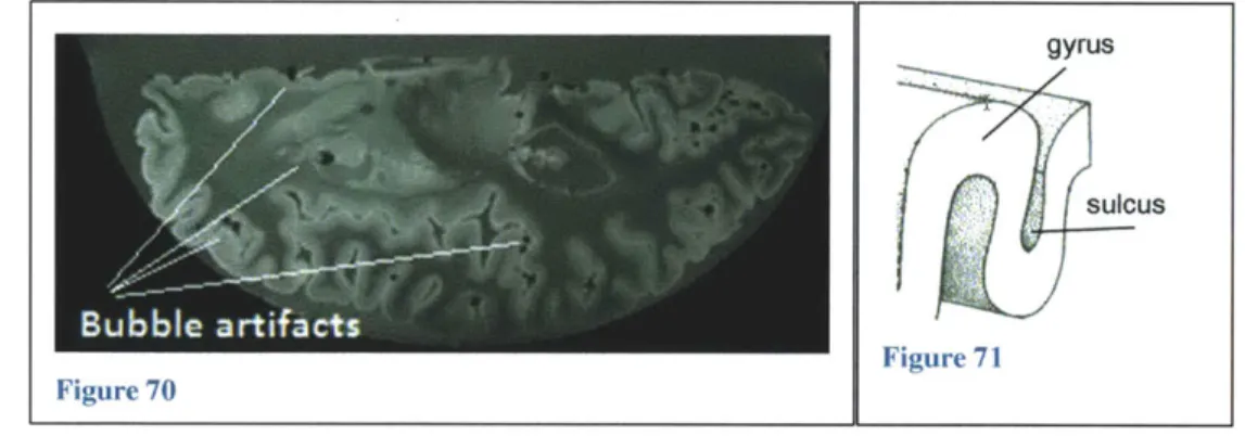
5.2. Rem oving bubbles ... 69
5.3. V acuum only Test ... 70
5.4. V ibration Under V acuum ... 72
5.4.1. Shake, Rattle, and Roll apparatus... 72
5.4.2. Initial shake test results ... 73
5.4.3. Shake Test: Surfactant and Frequency Sweep ... 74
6. Conclusions...75.
6. Conclusions ... 75
7. Future W ork and Design Im provem ents ... 76
7.1. Quantify Receiving Array alignm ent sensitivity... 76
7.3. Brain Holder Bolted Flange... 77
7.4. Continue Im proving Degas M ethod... 77
1.
Ex-vivo background
1.1.
ExVivo
MotivationThe aim of MR-based Architectonic Segmentation is to develop MR based tools to analyze the laminar
architecture of the cerebral cortex. The cerebral cortex is the folded sheet of neural tissue that forms the outer most surface of the cerebrum. Being able to detect variations or changes in its laminar architecture may provide incredible insight into diseases such as epilepsy, schizophrenia, dyslexia, and autism. The ultimate goal is to be able to automatically define laminar boundaries using high-resolution MRI in hundreds or thousands of samples.
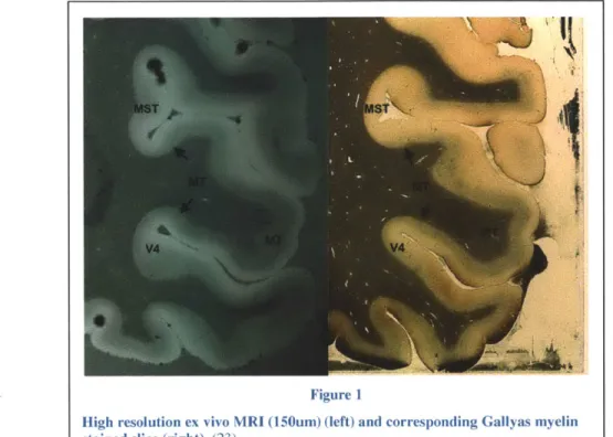
To achieve this goal, information from ex vivo samples will be used to infer architecture in in vivo samples. The immediate goal is to optimize ex vivo imaging to obtain undistorted 100um isotropic images over an entire hemisphere with uniform contrast. Figure 1 shows a high resolution ex vivo MRI used to identify anatomical regions of the cortex compared to a traditional stained slice on the right. Using MRI to define laminar boundaries is very advantageous compared to the traditional, extremely tedious process of manually defining laminar boundaries by cutting and staining which leads to distortion. Figure 1 shows and MRI generated "slice" next to a traditional sample which is manually sliced, stained, and labeled. The optimization of ex vivo imaging requires the design and construction of a special
purpose sample holder and ex vivo coil arrays to match. In addition, a process for removing trapped air in
the samples is required. The apparatus used to hold ex vivo samples during imaging is critical to
resolution. Spacing between the sensing coils and sample, motion of the sample, and air bubbles in ultra-high field strengths all contribute to reducing the signal to noise ratio.
The 32channel 7T design presented here will be the first 32 channel ex-vivo coil for use at 7T. It will be used at the Athinoula A. Martinos Center for Biomedical Imaging (3).
1.2.
MRI FundamentalsMost Magnetic Resonance Imaging (MRI) acts on the Hydrogen nuclei and its single proton. The basic idea is to disturb the precession of these nuclei then differentiate mater by how long it takes the
precessions to relax back to their original motion. The key to MRI is using magnetic gradients to alter precession phase and frequency as a function of position. The spinning nucleus has an intrinsic angular momentum (a property of fundamental particles) and magnetic moment vector Fn due to the electron spin around the nucleus. Just like a top under the influence of gravity, the moment vector of the nucleus will precess around the direction of an external magnetic field. There are three main magnetic fields used in MRI, the first of these is the BO field. BO is a very strong (in clinical machines 1.5 Tesla -7 Tesla) static
magnetic field which aligns most (those with low enough thermal energy) of the nuclei in the BO direction Z down the main magnet bore of the MRI.
Precession Path % Magnetic Moment Vector v--***' N - -Figure 2 (14) Figure 3 (14)
The external moment applied to the nucleus as a result of Fn and B0 is C = x , we also know from
dynamics that the sum of external moments equals the time rate of change of the angular momentum dl
vector. C = i x Bo = W this leaves us with a differential equation with the solution I = De -i which
Larmor frequency and is the frequency at which the nucleus magnetic moment about BO.
vector in will precess
The net magnetization vector M is the vector sum of all the individual magnetization vectors fI. It is very important to note that under the presence of the static magnetic field BO, M does not precess. This is because individual nuclei are precessing at random phases, and the x component of their magnetization moment is canceled by other nuclei's magnetization moments that are out of phase. Figure 4 shows how
the magnetization vectors of two nuclei precessing 1800 out of phase (both precess about Bo ) would cancel in the x direction and the net magnetization vector is the sum of the y components.
Excitation
V(t) To get a signal out of the system we want to get a "wiggle" out of
M so that a voltage can be created by Faraday's law of induction.
To get this "wiggle" we can apply an oscillating magnetic field, called B1, in the x y plane. The source of this oscillating field is the magnetic component of an RF signal. If we simply excite at
Figure 5 induced voltage in a wire some random frequency not much will happen, however (this is
loop ue to magnetic field oscillations; key!): if we excite at the Larmor frequency the nuclei will start
Faraday's Law (14)
precessing in phase with each other! Now the net magnetization vector M is not only in z, but has components in the x y plane because the precessions are going in phase
ly
with each other and the in plane components do not cancel. From a mechanical perspective think of the masses in Figure 6 oscillating at the same natural frequency to but at random phases. Now if we drive the base at ),, = , the masses will come into phase with each other, and the magnitude will grow.
Just as for the B0field the rate of change of this new oscillating net field can be expressed as : = M x B - (01 = -YB1
If Bi is sufficiently strong and/or long enough in duration R can rotate 90', the z component is gone, and
this is called a 900. pulse. Any rotation angle can be created provided the pulse is sufficiently long and intense.
Relaxation
After the B1 field is removed (RF pulse), the processions begin to go out of phase again. The x y
components of the magnetization vector begins to fade and the Mz component begins to grow again.
RF excitation pulse: ITEN RF .a Time Voltage (Signal) Mx
Oscillating voltage detected at receive coil: the MR signal
Zmagnetization returning to equilibrium with time constant TlI
XY magnetization decaying b/c of dephasing with time constantT2
Figure 7 (20)
M M M M
K K K K
What we are ultimately after are the T1 and T2 time constants that describe the envelope of signal decay as the nuclei de-phase and settle back to the BO direction after excitation (among other measures such as proton density). T1 and T2 are tissue dependent and are what give the MRI image contrast and allow
tissues to be differentiated. The receiving coils pick up this free induction decay or FID signal.
Encoding Space
The key to encoding space in MRI is the Larmor frequency's linear dependence on magnetic field strength. A magnetic gradient Gz, in the z direction, can be applied on top of the very strong BO field so that the Larmor frequency of the nuclei is linearly dependent on the Z
position. We can excite "slices" in the z direction with location and thickness determined by the center frequency and bandwidth of the RF excitation pulse defined by:
Af
= AzGzypSimilarly to encode position in the x direction we can apply another magnetic gradient Gx in the x direction. So the Larmor frequency for a nucleus with X and Z coordinates is:
o = ypBO + ypGxx + ypGzz So in general the FID signal coming from a selected "slice" is:
s(t) oc
if
m(x, y)e-i(xY)t x yWhere m(x,y) is the decay envelope of the FID signal. Position encoding in the x and z directions is called frequency encoding.
To encode position in the y direction phase encoding is used. To encode phase in the y direction an 900 RF pulse is applied, as the precessions begin to de-phase, a gradient Gy , in the y direction is switched on for time r. This imparts an in phase precession in the y direction which varies linearly in y. When Gy is switched off the spins go back to their x z precessions but maintain a linear de-phasing from the Gy pulse.
A 180' pulse is then applied which without the y pulse, would reverse the random de-phasing and bring
all the spins back into phase in the x y plane. However with the Gy pulse, the spins maintain their linear de-phasing after the 1800 pulse. After the 1800 pulse the spins are encoded in the y direction by their phase shift. The phase shift acquired is described as:
<p(y) =
f
w(y)dt = CoT = (ypyGy)rIncluding this in our FID signal we have:
s(t) oc
ff
m(x,y)e-j [YpZGz+YpGx+(YpyGy)T ]dydxThus the frequency of the FID signal received from each spin is a function of x y and z position and the applied magnetic gradients. Thus each x y z region has its own unique frequency and corresponding envelope of decay m(xy). An inverse 2d Fourier transform can be applied to recover this m(xy) magnitude which gives that x y z region, or voxel, an intensity.
Some things that affect image quality in MRI are the Homogeneity of the BO field and spatial
homogeneity of the B 1 field. Effects from eddy currents also interfere with the applied fields; these eddy currents can be generated on any conductor in the magnet bore. Changes in magnetic susceptibility can induce magnetic gradients which distort the applied fields; this effect is increased with field strength. Lastly Brownian motion of the water protons contributes to thermal noise.
2.
Design of the 7T 32 channel ex vivo coil assembly
2.1.
Fundamental Requirement OverviewThe main requirements of the ex-vivo scanning assembly are:
1) Position the brain and all associated transmitting/sensing electronics at the iso-center of the 7T magnet
bore
2) Contain the brain in a re-sealable vessel for scanning and storage
3) Place the receiving coils as close to the brain as possible for high resolution images and
4) Do not distort or damage the brain tissue. Additionally, air bubbles cause artifacts during imaging and must be removed in a separate process.
2.2.
Previous Approaches
All previous work was carried out at the Athinoula A. Martinos Center for Biomedical Imaging (3)
2.2.1. Previous Holder Design
One previous brain holding approach involved a molded fiberglass shell and flat plate lid as shown in Figure 9. A degassed brain sample, sealed in a bag, is placed in the shell for scanning. One difficulty
with this approach is the lack of features on the shell to aid the receiving coil layout as discussed in 2.2.3. Receiving coils must be tessellated over the surface of the shell and this design requires a tedious trial and error process to position the coils. Bunching of the brain bag also poses a problem when imaging due to changes in magnetic susceptibility at the liquid, bag, and air interfaces. Another challenge in this design is the lack of a rigid, cohesive mechanical structure to support the electronic components.
Figure 9
Another previous approach to holding the brain was a 3d printed holder that conformed to the brain (Figure 10 ). This design had two main drawbacks: 1) the fused deposition printing process resulted in a porous structure that was not air or liquid tight leading to leaking PLP preservative 2) while the holder
conformed nicely to one brain, the high variability in brain size rendered the holder less useful with other brains.
2.2.2. Previous Birdcage Design
The "birdcage" is a cylindrical array of RF coils that transmit the B 1 excitation field. The "birdcage" surrounds the sample and receiving coil array and is concentric with the BO magnet bore. Previous successful designs employed a large cast acrylic tube onto which the transmitting coils were laid. Figure 11 below shows a previous design. The longitudinal and circumferential copper strips are the transmitting coils.
Figure 10
2.2.3. Previous Receive Array Design
The receive array former in this work builds on the most recent array designs from the coil
building group at the Martinos center. Figure 12 shows a recent head coil with a 3d printed former
that includes the hexagonal coil layout features and preamp standoffs.
2.2.4. Previous Degassing Approach
The previous degassing method was to submerge the brain in PLP solution in a heat-sealable bag, then
massage and tap the brain to remove bubbles. The air collected at the top of the bag was then sucked out
with a needle and syringe and the bag resealed. The sealed bag was then placed in the scanning
apparatus. The process proved to be lengthy and unable to remove all bubbles.
2.3.
The Manufacturing Challenge
The ex-vivo coil assemblies are one-off, each design fulfills a different need or is an iteration of previous
work. They are built in lab; the exploratory nature of the process and the need to iterate demands flexible,
13
-e
Figure 12
low cost, and rapid manufacturing methods. Shipping work out to other shops is often difficult because of the need to rapidly make changes during the building process or to quickly implement new ideas.
2.4.
The Manufacturing SolutionIn this project a unique set of existing and newly developed tools are brought together to enable less expensive development of ex-vivo coils and to enhance the existing build capabilities. These
manufacturing tools and design methods are intended to provide the flexibility and capability to produce components with increased accuracy and improved properties while expanding the limits of what is possible to build in-lab. Increasing coil building ability opens the possibility of developing a wide range of custom coils to improve all MRI imaging.
Fundamental
Figure 13
imentsDesign
Principles
Prior
Work
Figure 13 shows the general flow of concepts and processes in the design and construction of the ex-vivo assembly. Most important is how connected and fundamental the manufacturing methods are to the design. Many of the challenges associated with the ex-vivo coil design are manufacturing related and an important aspect of this work is the closed loop from manufacturing process 4design rmake and back around. The solution not only requires a product design but also a concurrent process design as well.
2.5.
Design OverviewThis thesis presents the mechanical design and construction of a 32 channel 7T array. All electrical design and construction is carried out by members of the Martinos MRI coil group who have been designing and building coils for over 10 years. In the new design of the 32 channel ex-vivo brain holder (shown in cross section in Figure 14), some innovative design features and processes have been
structure of the 32 channel coil is based on a stiff, protective, cohesive chassis that minimizes the length
of structural loops. This chassis or frame provides alignment and reference during assembly, and a
structural "ground" for component and subassembly mounting. The design is composed of a series of
concentric rings, connected by stringers, into which a skin is bonded forming a tube for the transmitting
array. This design is very similar to airplane fuselage construction and results in a stiff, well aligned, low
cost structure. "Formers" are used to describe the mechanical structures for the transmitting and receiving
coil arrays because they form the coils to the proper geometry.
2.6.
Detailed Requirements and Design Solutions
The design requirements of the ex-vivo brain scanning assembly are: 1) Position the brain and all associated transmitting/sensing electronics at the iso-center of the 7T magnet bore 2) Place the receiving coils as close to the brain as possible for high resolution images 3) Contain the brain in a re-sealable vessel for scanning and storage 4) Do not distort or damage the brain tissue 5) air bubbles cause artifacts during imaging and must be removed in a separate process. Figure 15 shows the completed scanning
assembly.
Figure 16
Requirement 1: Positioning
The ex-vivo coil assembly is placed on the patient bed of the 7T MRI and needs to be centered in the
magnet bore. The brain must be positioned at isocenter because the BO field is most homogenous there, the Gy,z gradient fields are most linear there, shim coils are centered there, and the RF transmitting coils must be centered there. The Birdcage frame was designed to nominally place the brain at isocenter and accommodations for small adjustments were made by using adjustable feet. The base is designed to use 3 non-parallel planes on the MRI bed to provide a unique and repeatable mounting orientation. The
primary reference is the bed bottom, secondary is the vertical back wall of the bed, and tertiary is the side wall on the bed. The number of feet required for each reference plane would be 3,2,1 if mounting were exactly constrained. However, for stability 4 feet were used on the primary reference. In this work it is not often that high positional accuracy dictates since each system is tuned to achieve desired electrical properties. Rather, it is repeatability that is important so that these tuned parameters remain as such. Requirement 2: Coil Placement
The shell for holding the receiving coils, known as the "coil former" (Figure 17), fully surrounds the inner holder and serves as the mounting location for the receiving coils.
Coil Layout Figure 17 Preamp mount
features locations
It is composed of two 3d printed shells. 3d printing was selected due to the complex geometry and need for only one set. The receive array is really the heart of the ex-vivo assembly and once built and tuned will not change and is sized to accommodate a limited range of brain sizes as discussed in 0. An array of
31 copper coils, each with a passive pre-amplifying circuit, must be tessellated over the surface of the
brain. The closer these coils are to the surface of the brain, the better the signal to noise ratio. The close proximity of the coils to the brain is the motivation behind ex vivo imaging as opposed to in vivo. The
coils all have overlap with their neighbors as shown in Figure 18 to cancel out mutual inductance between nearest neighbors. Figure 18 shows the 3d printed receive former, a preamplifier, and the receive coils.
Figure 18
Close up of receiving coils with preamps all laid out on 3d printed former
To guide the coil placement during assembly, a pattern of hexagons and pentagons were tessellated over the surface of the top and bottom coil former. Symmetric, evenly sized hexagons and pentagons were tessellated over the former surface in SolidWorks, details of the process are presented in Appendix A. These shapes were embossed on the 3d printed formers and dramatically speed the coil construction process by providing a layout template (4).
Receiving coils are tuned for one specific geometry, repeatability of coil alignment is important for consistent performance. Coupling between the coils is a function of the separation. Combined signal across all coils is strongly dependent on how correlated the noise is between the elements. To ensure repeatable alignment of the former halves in the XY plane a locating pin and stop were used. The pin is fixed to the bottom receiving former and passes through a close fit (.004" clearance) hole in the upper receiving former. This provides a constraint in the XY direction and eliminates two of the three degrees of freedom in the XY plane. A stop is the used to fully constrain the holder in the XY plane by removing the rotation DOF. Figure 20 shows the pin location as it acts as a rotation origin.
To find the most effective location of the pin, start by considering the direction of the force reaction between the pin face and surface of the part. Vector r is from the rotation center (pin center) to the pin/ part contact location, 0 is an angular displacement, n is the unit normal vector for the contact point on the part, and F, is the normal force reaction. For the greatest constraint stiffness we desire the moment about the origin created by F, to be maximized
Pin Stop Figure 19 -line segment vector . Figure 21 Figure 20
possible rotation displacements with pin only
F= -(r x 6) -+ 6 - (r
x
n)The sensitivity of the constraint force to rotation is: aF
-- = r x n
It is desirable to maximize this sensitivity for the greatest rotation constraint
To find the optimum rotation constraint location the perimeter geometry of the upper former bolt flange was extracted from CAD into a data file using DanCam, then a Matlab script carried out the (r x n) operation for all line segments forming the perimeter. Figure 23 shows the results graphically and pinpoints the ideal rotation constraint location.
r x 0
Figure 22
Requirement 3: Brain Housing
A re-sealable container for the brain is needed because it prevents the degased brain from coming into
contact with air and submerged in PLP. It also keeps the toxic PLP solution away from the rest of the ex-vivo assembly and eliminates human contact with the solution, this allows the brain to be safely handled and stored outside a fume hood. Each brain will be stored and degassed in its own "holder" which can be neatly and easily swapped out of the scanning assembly. Several of these holders were required and had to meet the following requirements: long term chemical resistance, liquid and gas tightness, two ports to accommodate the degassing process, ability to withstand 29.5"Hg vacuum pressure, see-thru, and durable. Due to the specific material requirements and the need for multiples, a substantial effort was put into developing a bench top vacuum casting system discussed in Section 3.
To address the chemical resistance, clarity, and casting requirements (low viscosity, low shrinkage, adequate gel time) Epon 315C epoxy was selected for initial prototypes. 3 months of continuous
exposure to the PLP solution revealed no changes in the material such as softening, pitting, discoloration, Magnitude of Cross Product
4.687 3.783 Origin o rotation -2880 1.977 0.170 43 ... 2.. ---- --- --- --- -- 0 13 4
xI
Figure 23or cracking. The highly cross-linked epoxy combined with the ability of vacuum casting to produce void-free parts allowed for gas tight holders. Repeated pressure testing validated the designs suitability to
withstand atmospheric pressure under full vacuum. However the Epon 315c and Epikure 3234 curing agent proved to be somewhat brittle and less durable than desired.
To address the poor toughness of the epoxy cast holders, a new set were cast using a rigid polyurethane (Freeman 1090) with a Shore hardness of 80 and a flexural strength of 11,00OPsi and a .1% shrinkage and 600 centipoise mixed viscosity. The finished urethane holders proved to be far tougher and able to withstand accidental drops. No data could be found on PLP chemical compatibility with urethane so long term compatibility with the PLP fixative will be tested.
Sealing between the top and bottom holder halves is accomplished with a vacuum cast silicone gasket discussed in 3.2.11. Various gasket thicknesses were cast to allow for slight holder volume adjustment to accommodate small variations in nominal brain size. Pockets were included in the sealing flange to reduce material usage and mitigate the effects of shrinkage in the casting.
Requirement 4: Brain Holding
The brain holder needs to lightly constrain the brain and position the receive coils close to the surface without squishing, distorting, or damaging the brain. The tissue is fragile and the brains overall shape
Figure 24
must be preserved. There is large variation in brain size and this variation proved to be very difficult to accommodate while satisfying the coil positioning requirements.
Means and Standard deviations for Brain Volume in Cubic Centimeters (5)
Women Men
Brain volume =1130 a= 112 y = 1243 o = 110
The brain was approximated as a half ellipsoid with principal axes lengths a,b,c where b=c. Thus the brain volume is approximated as: V = r 7T ab2
. A rough length to width (b/a) ratio of .8 was established
6
from measuring actual brains. Varying the brain volume up and down 1 standard deviation (so 1018 to 1242 for a woman's brain) and solving for a and b dimensions (using the .8 ratio) yielded a change from the nominal a and b dimensions of .125" in a and .1" in b. Thus the holder geometry was designed to allow for this approximate 1 standard deviation larger brain.
Adjustable volume holders are not possible because once built, the receiving coil geometry is set. It is a delicate and lengthy process to adjust and tune the properties of the receiving coil in harmony with the transmitting coil for optimal performance. An adjustable holder does no good when the receiving coils can't be adjusted as well.
Requirement 5: Integration with Brain Degas Process
The development of an improved brain degasing method is very important to improving ex-vivo scanning. Trapped air in the brain causes large blooms, or dark spots in the final image due to susceptibility gradients at the liquid/ air interface. The holder is integrated into the degas process; it serves as the low pressure vessel in which the degas process takes place and maintains an air-free, preservative-filled environment for the brain during storage. This meant that the holder must withstand the degasing processes including large amplitude vibration and external pressure when under vacuum. Degasing techniques and results are discussed in section 5. Two fittings are installed on the holders for the degas process, one is a vacuum port and one allows for fluid filling.
2.7.
B1 Transmitting Coil Design, The Birdcage
2.7.1. Transmitting Coil Function
Figure 25
Birdcage style transmitting coil schematic showing conductors and
blocking capacitors
Transmitting coils create the radio frequency B 1 excitation field that bring the Hydrogen nuclei precessions into phase. Although several different coil styles exist, this particular style is called a birdcage coil. The birdcage forms a series of conductive loops connected in parallel that surround the sample. These loops are fed RF pulses directly from the MRI pulse sequence generator. 16 axial "legs" create 16 loops, the more loops, the more homogeneous the BI field is. However more conductor area must be balance with the need for the birdcage to remain transparent to RF flux (6) and assembly effort. Sixteen legs has been determined to provide adequate homogeneity. Detailing the theory behind RF coil function is beyond the scope of this paper, for more information see (6) and (7). Birdcage coil design was guided by research staff at the Athinoula A. Martinos Center for Biomedical Imaging (3) who have been constructing coils for 10 years and have extensive coil building experience (4) .
Geometry requirements
Testing revealed that B 1 field intensity begins to fall off beyond the central 60% region of the coil. Thus the entire receiving array (19cm maximum dimension in the Z direction) needed to be inside this 60% region of the birdcage; this translates to a 32cm electrical length (measured from outer edge to outer edge of the circumferential end coils). 2 cm were added to either end for safety resulting in a 36cm total electrical length. The 10.25" diameter of the birdcage is the maximum possible diameter for the birdcage
while still remaining coincident with the main magnet bore. Any larger and the birdcage would interfere with the MRI patient table.
2.7.2. Birdcage Design
As the gradient coils are pulsed, large magnetic fields create eddy currents in the birdcage conductors. These eddy currents in turn produce perpendicular Lorenz forces. The larger the conductive strips are, the
larger the eddy currents are and in turn generate larger Lorenz forces. These Lorenz forces oscillate with the gradient pulses and can cause the skin of the transmitting coil to vibrate (8). To reduce eddy currents conductors are kept narrow (0.5" in this design). Further eddy current mitigation is provided by blocking capacitors on the axial and circumferential legs of the birdcage. These capacitors are tuned such that they act as an open at low frequencies which are associated with eddy current formation; this further
minimizes the area available for eddy current formation. At the high operational frequencies, the capacitors act as shorts and do not impede function. Figure 28 shows a unwrapped segment of the transmitting coil note the blocking capacitors.
Figure 27
The birdcage sheet laid flat with installed conductors 'II 4
4
IHI
16 of these legs around the birdcage circumference
HI
z
,HI
Figure 28
Schematic of a section of Birdcage Coil
The coils are constructed by laying strips of copper tape in very specific geometries on the tube surface then coupling breaks in the strips with capacitors. Using NC controlled equipment to cut the sheet allows accuracy in positioning the conductors which leads to better performance
Material requirements
The birdcage structure has to be electrically insulating, RF and MR transparent. Typically the birdcages are based on cast acrylic tubes. FR4 fiberglass has also been used in previous designs.
Sheet tube
The required diameter (10.25") was not available in any acrylic or polycarbonate tube; thus the shape and structure of the birdcage had to be created another way. Several options for creating the tube were considered which are outlined in Table 1.
I
I~4
l~.
0
a
I14i
F
A IMethod Advantages Disadvantages
Molded fiberglass with vacuum Very stiff, continuous, free of Poor bag-side surface,
bag residual stress dimensionally accurate mold
needs to be constructed
Molded fiberglass with matched Very stiff, continuous, free of Mold has to be strong,
molds residual stress, good surface dimensionally accurate, able to
inside and out remove part
Casting Good surface on both sides, mold Low strength, unknown
has less mechanical req's than resistance to thermal fatigue, low
fiberglass mold heat resistance
Rolled Sheet Excellent thickness tolerance and Requires frame to ensure surface finish, wide variety of dimensional accuracy materials available, cutting and
shaping can be done flat with NC
equipment, low cost, no mold required
Table I
It was decided to replace the cast acrylic tube with a sheet material having several advantages: wide selection of materials and thicknesses, low cost, and the ability to lay the sheet flat for cutting (laser, water jet, or by hand) and the laying of transmitting coils. The sheet was designed in SolidWorks as a sheet metal-type part with a bend radius equal to the birdcage radius. This allowed all the cutouts and feature to be placed with the sheet in a rolled configuration within the entire assembly, then "un-rolled" or laid out as a flat part which could be converted to a DXF file to easily and precisely cut the sheet on a waterjet. This ease and precision is not possible with a round tube and conventional waterjet. This method also allows future designs to use copper clad FR4 sheet then have the coils and electrical features routed out for enhanced precision.
Transmitting Coll Layout Locations
Rolled State Unrolled State
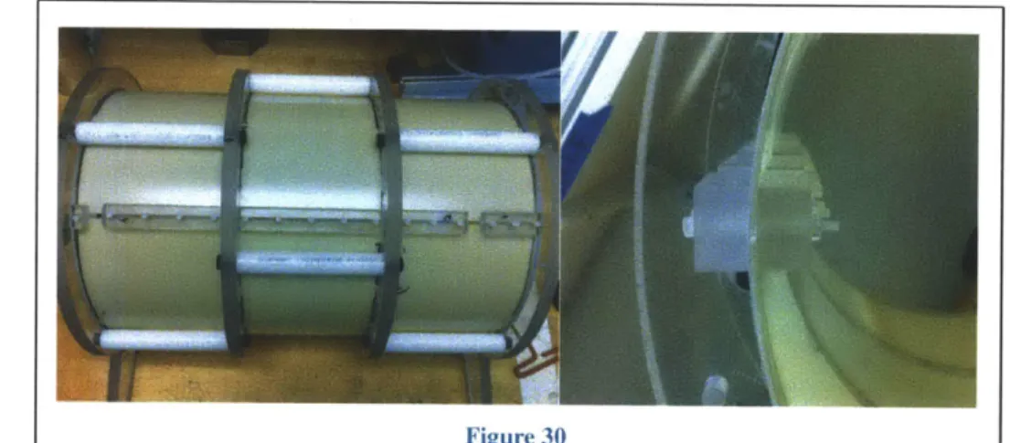
The "seam clamps" in Figure 30 are critical to making the sheet design work, especially in stiffer materials like FR4. These clamps have surfaces matched to the curvature of the birdcage and bridge the seam in the sheet. When tightened they force the edges of the sheet to be tangent. Without these clamps the sheet will take on a teardrop shape. Because the clamps bridge the seam gap, much "looser"
tolerances can be used for the sheet width, whereas prior to the seam clamp the sheet width had to nearly exactly match the inner circumference of the frame rings. As the clamps are tightened down the sheet will adjust its circumference to exactly match the frame ring similar to how a rolled poster will expand radially inside a poster tube until it matches the tube diameter.
Figure 30 Seam clamps enforce tangency at sheet seam
Birdcage Frame
Figure 31
Bare frame without transmitting surface or shield, cable mount plate and inner holder
Figure 32
To accommodate the rolled tube concept a ring and stringer style frame was developed. The concept for the frame is to provide a rigid, well aligned structure to provide a mounting template for the transmitting sheet. The frame itself is based on a series of 2d geometries each occupying they're own plane in the axial or Z direction of the birdcage. These planes are joined by stringers which provide axial alignment and spacing. The rings provide diametral stiffness and sheet constraint, the stringers provide axial stiffness and constraint. The birdcage is assembled by rolling the transmitting coil sheet (having been cut and coils laid out) and positioning it in the frame, bonding the sheet into the frame completes the
structure.
Bolted joints are advantageous for providing damping due to energy dissipation from friction at the joint interfaces. Glass filled plastic fasteners were used throughout the assembly. This approach proved to be successful as shown by the results plotted in Figure 33. Figure 33 represents one of the quality assurance measures used at the Martinos Center. The abscissa represents sample number, the ordinate is average signal intensity from a group of voxels located at the center of a gel phantom brain. Ideally the intensity would be constant for all samples since nothing is changing, but due to mechanical and electrical
disturbances, the signal varies. The white signal is actual, the green is de-trended to remove the effects of thermal drift, the blue line is a best fit trend line. A peak to peak (P2P) value of .5% is desired, the birdcage tested here achieved a P2P of .48%. This low variation in signal intensity is attributed to the structures stiffness and high damping.
2.7.3. Mounting Plate Subassembly
The concept behind the "mounting plate," shown in Figure 14 is to keep the receiving coil array, cable traps, cables, and additional electronics all solidly mounted to a single piece that can be removed and inserted into the birdcage as needed. The receive array sends signals from each of its 31 coils to passive preamplifiers, receivers for analog to digital conversion to RAID data storage for later post-processing. The ex vivo assembly is connected to peripheral equipment thru large diameter shielded cables which are permanently mounted to the mounting plate on one end and terminate with large connectors on the other. This subassembly concept prevents relative motion between the receive array, receive signal conditioners, MRI cables, and MRI cable traps. This eliminates undue strain on the delicate wiring connecting receive coils to signal conditioners and awkward handling during scanning preparations. The mounting plate ties directly to the structure of the main frame providing a solid interface between brain holders and frame. The generic hole pattern at the rear of the plate provides a mounting space for components.
2.7.4. Planar Geometries
Planar geometries are an important and repeating concept in this work because they allow rapid, accurate, and low cost production through the use of advanced manufacturing techniques like laser or waterjet cutting. The advantage of these methods over machining are: little to no clamping / cutting forces, rapid path generation, high speed, and low operator involvement. The advantage of planar parts over 3d parts with respect to 3d printing are: increased precision and dimensional stability, improved mechanical properties, and material choice. Planar geometries can take advantage of the as-manufactured surfaces of plate stock which are often held to tight flatness and thickness tolerances. This is illustrated in the face to face interface between the frame rings and mounting plate brackets.
Figure 34
3.
Manufacturing Processes
3.1.
Selecting ProcessesThe main requirements for selecting the manufacturing processes used were: Cost, ability to use the method in a small lab, wide material selection, and time. Successful execution of the design required a set of flexible prototyping tools that are low cost, and leverage common manufacturing capabilities. A major portion of the work was devoted to developing two such tools: the bench-top vacuum casting unit and a computer aided manufacturing program nicknamed "DanCam."
3.2.
The Bench-top vacuum casting unit3.2.1. Process Overview
Vacuum casting is a casting process in which the mold is filled while under vacuum to eliminate porosity and encourage complete filling of intricate molds. During casting the liquid material is pushed into the mold (which is held under vacuum) by atmospheric pressure or gravity. A basic overview of the process is as follows (the process is detailed in Appendix B):
1) The casting material is de-gassed under vacuum to allow buoyant forces to remove dissolved gasses
and bubbles. This step is extremely important to the success of the process because any trapped air or gasses in the casting material will cause foaming during filling and ruin the part. Material degassing will be further discussed in 3.2.5. 2) A vacuum is pulled in the mold cavity directly, or the mold is placed in a vacuum chamber. This pressure is important because it controls mold filling rate, forces on the mold, void elimination, and the propensity of the casting material to foam or boil. 3) A valve is opened to allow the liquid casting material to be pushed into the mold by gravity or a differential pressure. 4) After filling the vacuum is released, trapped voids collapse and are completely filled, and the part is cured.
33
Mold cavityunder vacuum
Figure 35
3.2.2. Advantages of Vacuum Casting
For prototyping of medical devices vacuum casting offers a number of distinct advantages. The largest advantage for this work was the ability to create void free parts. Voids weaken the ex-vivo brain holder, can cause artifacts in the MRI imaging, and may lead to fixative leakage. Void free-parts are due to the absence of entrapped air during casting
The main mechanism for eliminating voids is illustrated by the fact that there is roughly a 150 fold increase in gas volume between atmospheric pressure at 14.7 psi and a casting pressure of .Olpsi (29inHg). Figure 36 shows how the vacuum casting process is able to effectively fill re-entrant sections of the mold without the need to vent these sections as with more conventional casting processes. After the vacuum is released casting material (resin in this case) is drawn up into the reentrant cavities. With virtually no trapped air to push back on the resin the cavity may be completely filled. Bubbles not removed by buoyant effects during the casting process are essentially squeezed down to a very tiny volume after atmospheric pressure is reapplied.
Cavity void of Air
During filling, mold under vacuum After filling and vacuum released
Figure 36
Figure 37 shows a simple experiment demonstrating this filling concept; the tube was filled with air initially with one end held under water and the other end plugged. Everything was placed in a vacuum chamber. When vacuum was applied (29.3inHg in this case) the air expanded and pushed out of the submerged end of the tube. When the vacuum was released water was pushed back into the now void tube almost completely filling it. The tiny bit of remaining air can be seen in the picture, this is all that was left from the full tube of air. Lower pressures could remove more air but were not practical for the vacuum casting because of vapor formation from volatiles in the resin boiling.
I
Figure 37A second major advantage of vacuum casting is the freedom to select any practical material for creating
the master model. The material for the master model can be selected for its ease of forming regardless of the material requirements for the finished part. For example machineable wax is relatively inexpensive, can be melted and reused, and is very easily machined. This allows master models to be cut on low stiffness machines with high feed rates. This wax master model is used to create a mold which in turn can be used with any number of cast-able materials that can be optimized for the finished part requirements. Casting uncouples mold material requirements from part requirements. The choice in casting materials is
an important factor in many medical devices because of regulatory requirements, stiffness and strength requirements, optical properties, magnetic properties, chemical resistance, bonding properties, etc. Table
2 shows a list of different casting materials for the brain holder.
Material Flexural Tensile Hardness Linear Mixed Viscosity Strength Strength Shrinkage centipoise
(psi) Epoxies:
Epon 815c cured with --- 10,800 85 1% 600
Epikure 3234 (16) Polyurethanes: Freeman 1090 (15) 11,000 2,500 80 .1% 600 Freeman 1080 (17) 9,500 6650 80 .1% 150 Table 2
35
3.2.3. Benchmarking
Typical vacuum casting machines are large and expensive. The goal in this project was to create a small, low cost desktop unit to fulfill most of the functionality of the larger more expensive units. Renishaw is the primary manufacture of these machines. The units are quite large; the smallest unit is their 5/01 model and measures 1.175 x 1.2 x .594 Meters. Additionally this unit is out of the range of labs and small prototyping firms that could make use of this technology. These units have one open chamber; the casting material is mixed and poured from the upper chamber into the mold which is positioned on an adjustable pedestal in the lower section of the chamber. The whole process takes place under vacuum and the casting material is pulled into the mold by gravity alone. Higher end units like the 5/04 have two separate chambers and can use a pressure difference between the two to force the casting material into the mold, very similar to the desk top unit presented in this work.
Mixing and pouring
section
mold pedistal
Figure 38
Renishaw 5/01 ULC (18)
3.2.4. The Desk Top System Concept
The basic system shown in Figure 39 is composed of a vacuum pump [1], vacuum chamber [2], resin supply pot [3], resin flow control (hidden from view) [4], resin pot vacuum supply [5], resin supply line
[6], and the silicone mold and vented risers [7]. The pump [1] pumps down the chamber [2] and can also
supply vacuum to the resin pot for degassing or to control the pressure differential between the resin pot
[3] and the vacuum chamber [2]. After casting pressures are achieved, the resin flow control valve [4] is
opened and resin flows into silicone mold [7]. The vent tubes coming out of the top of the mold are filled last and serve as risers to supply liqid material to the casting during recompression. After the mold is completely filled the vacuum is released. Resin in the vent/risers is drawn into any pockets that may have existed while under vacuum, the casting is cured in place.
Figure 39
The chamber used is a polycarbonate dome that splits in the middle to allow easy access. The vacuum dome has two ports and it's transparency plays an important role in the casting process by allowing the user to monitor and control the mold filling. Polycarbonate is an ideal chamber material due to its toughness and clarity. The vacuum pump used is a 1OCFM unit capable of 15pM of Mercury. The large throughput of the pump helps to quickly bring down the pressure of the chamber, a huge benefit when degassing mixed resin with short gel times.
3.2.5. Degassing the Casting Material
The Importance of degassing the casting material cannot be stressed enough. The best practice was found to be degassing the thermoset components individually, then gently and evenly mixing them to avoid the introduction of air, then degassing the mixed volume. Degassing is very important because if the material contains any dissolved gasses or bubbles it will foam vigorously as it enters the low pressure atmosphere inside the mold. A foam filled mold is nearly impossible to recover from and the casting is almost certainly ruined. A slow, laminar filling of the mold without bubbles is key.
Degas time for Epon Effect 815c resin and
Epikure3234 curative
none Foaming as resin enters the mold, ruined casting 1min Foaming and bubbles present, ruined casting
5min No foaming, but noticeable expanding bubbles in resin supply line 15min No foaming, no noticeable bubbles in resin supply line, smooth filling
3.2.6. Mold Filling Pressure
The mold filling pressure was also an important variable to a successful cast. One advantage to a higher differential pressure between mold and resin supply is faster filling especially with more viscous
materials. However this advantage must be carefully balanced with the tendency of the casting material to foam under increasing vacuum due to volatiles evaporating. It was found that that the Epon 315c epoxy and curing agent contained volatile compounds that had a vapor pressure around 29.5inHg so that no matter how long the mix was degassed, if casting was attempted at or below 29.5inHg the mix would boil in the mold and make casting quite difficult. With the 315c epoxy mix best results were had casting at about 25inHg, this seemed to inhibit foaming and excessive bubble growth, while still providing vacuum casting advantages.
3.2.7. The Pinch Valve
In order to reduce material waste, provide greater flow control, and allow the unit to be automated for higher throughput and repeatability, a servo controlled double pinch valve was developed. The pinch valve is a flow control valve that is installed between the casting supply pot and the mold. One motivation behind developing this valve was to dramatically shorten the length of tubing between the casting supply pot and the mold. The advantages can be seen in the Poiseulle equation AP =
where the pressure differential required to produce a given flow is linearly related to the length of the pipe (or tube in this case). The Servo valve allowed the tube length to be reduced from 16" to 7" resulting in a 56% reduction in differential pressure for a given flow, this could also be looked at as a - 130% increase
in flow for a given pressure (all other variables held constant). This was not a huge factor for less viscous epoxies but is very important for more viscous materials where any amount of vacuum in the mold space is unable to draw material through the supply tube. Another motivation behind the servo valve is that it allowed the casting supply pot to be placed inside the vacuum chamber along with the mold; this negates the need for the casting supply line to run through ports in the chamber. These ports are " ID and act as flow restrictions for more viscous or filled materials; the servo valve can accommodate up to /2" OD
because all tubing that the resin comes in contact with must be thrown away, and a good amount of resin
is always left in the tubing after casting. Having the resin supply vessel in the chamber allows for
materials with a very short gel time to be used because the degassing can take place while the mold is
being pumped down, not in a separate process, this saves valuable minutes. Another motivation for the
pinch valve is that it allows for the process to be fully automated in the future. Once parameters were
established for a given mold and casting material. The process could be automatically repeated and
reduce user involvement and increase process control and repeatability.
3.2.7.1.
Servo Pinch Valve Design
Adjust Screw
Figure 40
Pinch Valve model
The design requirements for the pinch valve are: 1) the valve can have no contact with the fluid 2) the
valve must accommodate a range of tube sizes 3) the valve must provide variable flow control. A pinch
style valve seemed ideal for this application since it avoids fluid contact. The design is based around a small hobby servo because they are cheap and provide high torque of 90in-oz. To convert the rotary motion of the servo to linear motion of the pinch valve, a cam and slider mechanism was developed. The cam and slider offer a number of distinct advantages: 1) The cam can be designed to provide a linear relationship between servo rotation and slider motion or a falling leverage ratio between the two so that the servo has more mechanical advantage as the tube is pinched. One could even design a feature in the cam so that zero holding torque is required when the tube is fully pinched off. The point here is that the cam provides many modes of operation and is easily changed to modify the function of the valve. 2) The sliders remove any tangential friction forces that the cam would experience if it acted directly on the
tubing and provide the proper geometric constraints for the cam analysis to be valid. To mitigate slider jamming a length to width ratio of 2 was used.
The valve is designed to pinch the tube in two places. This allows for more range in resistance
adjustment since the fluid must pass through two resistances in series. More importantly the two tubes cause a symmetric load on both faces of the cam, this results is a pure torque on the servo and removes any bending moment on the servo shaft that would bind the motor and reduce the life of the valve. If necessary the valve can function in a single pinch mode. The backup sliders Figure 41 are adjustable to accommodate different tubing sizes.
Figure 41 shows the pinch valve in operation with a small silicone mold. This is all inside the vacuum chamber.
Design parameter
Total lift .3 inches
Total rotation 90 degrees
Displacement R=k*e
equation (linear)
Lift constant k .191
Table 3
To create the cam for the pinch valve, the radius of curvature R needs to be described as R=f(O) in polar
coordinates. Y, the lift height shown in Figure 42 is described by Y=k6.
R(6)= (Ro+y)2 +s 2 where y =kf From Uicker (9):
S=
dyk dO Replacing: s and y R(0)= (R0+k) 2+k2 E(uation 1 3.2.7.2. Cam DesignThis polar equation was used to create a cam profile of 180 points which was in turn converted to g-code and machined on an Easy-Track mill using DanCam. The cam profile output from Matlab is shown below in Figure 9 and the completed cam in the pinch valve assembly is shown in Figure 44.
04 03/ 0.2 0.1 0 .02 -0.3 -0.4 06 -04 -02 02 04 06 Figure 43 Figure 44
3.2.7.3. Lessons Learned / Improvements for Rev. 2
The main lesson from the pinch valve is the importance of designing for failure, a basic design concept that is not fully appreciated until the mistake is made. The servo actuates to pinch off the tubing, so the valve is nominally open. This is not what you want controlling the flow of casting material, this valve should be normally closed so in the event of failure the valve shuts off the flow. Lessons were also learned about designing slots for linear motion. In the interest of time and simplicity, the slots were all machined into the valve body. For low forces, speeds, and cycles, this was acceptable. However, careful attention must be paid to the depth of cut, cutter size, and milling technique when making this sort of slot to avoid irregularities in the sliding interface that may cause jamming. Figure 45 shows the importance of chamfering the slider to avoid interference due to imperfect cutter geometry.
Bad Design, cutter is not perfectly square Better Design, chamfer corner of slider at end, slider will jam
I)
Set
~
~
C -V' et kCa45oFigure 46
Concept sketch for simpler, more robust pinch valve
An improved design could be composed of two flat "jaws" hinged at one end and pinch the tube near the pivot, very similar to a nut-cracker. A spring at the opposite end would keep the valve nominally shut. A cam between the jaws would twist to spread them apart and allow fluid flow. The cam would be driven
by a servo that pivots at one end to allow it to rotate in the flat plane of the jaws. This allows the cam to
self-center between the jaws as they open and close. This design would be very easy to build, no bending moments would be applied to the servo shaft, and there is no concern about binding as the valve actuates.
3.2.8. Silicone Molds
Although vacuum casting can work with nearly any mold material, for this work silicone molds were selected due to their ease of manufacture and excellent release properties. Typically when working with thermosetting resins (or almost any casting and molding operation), careful attention must be paid to the surface finish of the mold and a variety of surface treatments must be applied to prevent the part from being stuck into the mold. Silicone adheres very poorly with the casting materials used (epoxies and polyurethanes), no special surface preparation was needed. Typically a mold is cast off a master model,
this master model must have excellent surface finish which requires extensive smoothing and polishing. With the silicone molds, master models could be used immediately after machining or 3d printing to cast the molds with little to no attention paid to their surface finish. Attempting this with any other cast-able mold material would result in your master model being permanently adhered in the mold. Another advantage to the silicone molds is their flexibility. Having a flexible mold allows features like small undercuts to be cast without needing much more complicated multi-piece molds. Having a flexible mold makes demolding quite easy compared to the often frustrating and lengthy process of removing parts from hard molds. Silicone molds allow can produce complex parts with features like undercuts and are often used to create functional prototypes for parts that are to be injection molded.
The expected mold life is around 50 parts and sometimes up to 100 depending on the mold geometry and the use silicone sprays to keep a fresh mold surface.
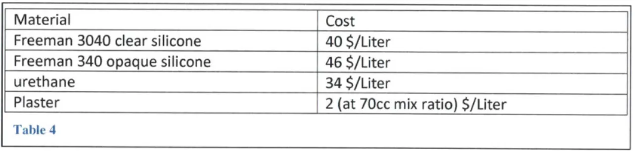
Table 4 below shows a comparison of cost between some common casting materials.
Material Cost
Freeman 3040 clear silicone 40 $/Liter Freeman 340 opaque silicone 46 $/Liter
urethane 34 $/Liter
Plaster 2 (at 70cc mix ratio) $/Liter
Table 4
The flexibility of Silicone molds is a great benefit during demolding, but during casting it can be a challenge. During mold filling the flow rate must be kept quite low to avoid pressure from building up in the mold due to flow resistance of the casting material. Initial tests confirmed that filling the mold too quickly caused the mold to bulge and the seal around the parting line to fail resulting in epoxy resin leaking out. For thin walled castings, flow rates of lmL/s worked well based off knowing the casting volume and time to fill.
Mold closure force is an important parameter is setting up for vacuum casting. This closure force is:
F = Aprojected * P
P is the differential pressure between the resin supply and mold, and A is the area of the casting projected onto the parting plane. Rigid backing plates or tape wrapping was needed to prevent the mold halves from separating during filling.
To get a simple closed form solution for approximating how thick the mold needs to be, the mold can be approximated as a simply supported rectangular beam with a distributed pressure load. This is a worst case approximation because the mold section is assumed to be supported on only two ends, not all 4 sides