Publisher’s version / Version de l'éditeur:
Construction Technology Update, 1998-07-01
READ THESE TERMS AND CONDITIONS CAREFULLY BEFORE USING THIS WEBSITE. https://nrc-publications.canada.ca/eng/copyright
Vous avez des questions? Nous pouvons vous aider. Pour communiquer directement avec un auteur, consultez la
première page de la revue dans laquelle son article a été publié afin de trouver ses coordonnées. Si vous n’arrivez pas à les repérer, communiquez avec nous à PublicationsArchive-ArchivesPublications@nrc-cnrc.gc.ca.
Questions? Contact the NRC Publications Archive team at
PublicationsArchive-ArchivesPublications@nrc-cnrc.gc.ca. If you wish to email the authors directly, please see the first page of the publication for their contact information.
NRC Publications Archive
Archives des publications du CNRC
Access and use of this website and the material on it are subject to the Terms and Conditions set forth at
Sound isolation and fire resistance of assemblies with fire stops
Nightingale, T. R. T.; Sultan, M. A.
https://publications-cnrc.canada.ca/fra/droits
L’accès à ce site Web et l’utilisation de son contenu sont assujettis aux conditions présentées dans le site LISEZ CES CONDITIONS ATTENTIVEMENT AVANT D’UTILISER CE SITE WEB.
NRC Publications Record / Notice d'Archives des publications de CNRC:
https://nrc-publications.canada.ca/eng/view/object/?id=ff2bfe42-7d10-45ca-b926-86e114705d87 https://publications-cnrc.canada.ca/fra/voir/objet/?id=ff2bfe42-7d10-45ca-b926-86e114705d87b y T.R.T. Nightinga le a nd M.A . S ulta n
This Update examines various fire-stopping techniques that meet the intent of
the National Building Code of Canada (NBC) w ith respect to fire resistance and
that do not adversely affect the sound isolation of the w all assembly. The
information is derived from the results of an industry-sponsored consortium
project led by the National Research Council’s Institute for Research in
Construction (IRC).
1C o n s t r u c t i o n T e c h n o l o g y U p d a t e N o . 1 6
Th e Nation al Bu ild in g Cod e of Can ad a (NBC) 1995 requ ires th at w ood -fram e con stru ction h ave a fire stop (a m aterial th at is p laced across th e con cealed air sp ace in a w all) at each floor/ ceilin g level to block th e p assage of flam e an d sm oke in p artition w alls con -tain in g com bu stible m aterials. How ever, in m u lti-fam ily con stru ction , certain typ es of m aterial an d m eth od s of in stallation m ay in trod u ce p h ysical con n ection s betw een th e d w ellin gs, an d w h ile th ese con n ection s m ay be d esirable for fire an d stru ctu ral reason s, th ey can be d etrim en tal to acou stical p rivacy.
A recen tly com p leted m u lti-d iscip lin ary p roject u n d ertaken by IRC focu sed on w ays to p rovid e th e n ecessary fire resistan ce w ith ou t com p rom isin g th e sou n d isolation in w alls betw een d w ellin g u n its. Th e resu lts of th e p roject are su m m arized in th is Up d ate.2,3
Eva lua t ing t he Fire Re sist a nc e of Fire -St op M a t e ria ls
Th e fire-resistan ce p ortion of th e stu d y w as con d u cted in p arallel w ith th e acou stics p ortion to en su re th at acou stically effective fire-stop m eth od s or m aterials w ou ld also satisfy th e in ten t of th e NBC w ith resp ect to fire resistan ce.
Th e NBC clearly sp ecifies w h en an d w h ere fire stop s are requ ired , an d for h ow lon g th ey m u st resist th e p assage of flam es. How ever, a su itable stan d ard ized test m eth od for evalu atin g th e variou s fire-stop p in g tech n iqu es d id n ot exist at th e in cep tion of th is p roject. Alth ou gh th e NBC m akes referen ce to CAN/ ULC-S101-M89, “Stan d ard Meth od s of Fire En d u ran ce Tests of Bu ild in g Con stru ction an d Materials,” th is stan d ard is p rim arily in ten d ed to be ap p lied in th e testin g of in d ivid u al w all or floor assem blies rath er th an in tersectin g assem blies. Th is m ad e it d ifficu lt for th e con sortiu m steerin g com m ittee to d eterm in e h ow th e stan d ard cou ld be ap p lied to evalu ate fire-stop m aterials at th e w all/ floor join t. For th is reason , before m eth od s to red u ce fire sp read th rou gh w all/ floor join ts cou ld be in vestigated , th e in ten t of th e NBC, as stip u lated in Sen ten ce 3.1.11.7.(1), h ad to be in terp reted an d a test m eth od th at satisfied th is in ten t h ad to be d efin ed .
Test Method and Failure Criterion Th e steerin g com m ittee, in con su ltation w ith IRC cod es ad visors, agreed to test th e assem blies by exp osin g th e bottom of th e floor/ ceilin g join t to a fire th at rep licated th e CAN/ ULC-S101-M89 tem p eratu re/ tim e relation sh ip , u sin g IRC’s p rop an e-fired
Sound Isolation and Fire
Resistance of Assemblies
w ith Fire Stops
2
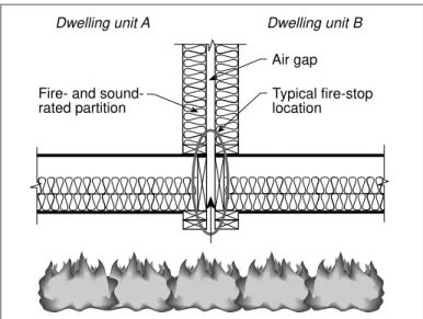
h orizon tal fu rn ace. (See Figu re 1 sh ow in g a section th rou gh a w all an d floor/ ceilin g assem bly.) Th e p rop agation of th e flam e u p in to th e w all cavity w as m on itored .
Th e NBC requ ires (in Article 3.1.11.7) th at m aterials u sed to sep arate con cealed sp aces, su ch as w all cavities, rem ain in p lace an d p reven t th e p assage of flam es for n ot less th an 15 m in u tes w h en su bjected to
th e stan d ard fire exp osu re of CAN/ ULC-S101-M89. Th u s, a fire-stop ap p roach w as con sid ered by th e con sortiu m steerin g com -m ittee to h ave -m et th e in ten t of th e NBC if, after 15 m in u tes, th e fire h ad n ot sp read in to th e w all cavity above th e floor level. If, at 15 m in u tes, flam es w ere visible or th e h ot gases reach ed a tem p eratu re of 550°C, in d icatin g th e p resen ce of flam e, th e fire-stop ap p roach w as con sid ered to h ave failed . Fire-Resistance Test Results
Th e assem blies tested can be grou p ed in to tw o categories:
• system s w ith an exp licit fire stop , an d • system s w ithout an exp licit fire stop .
S y ste m s w ith e xp licit fire -stop m a te ria ls
Of th e fou r m aterials tested as fire stop s, tw o w ere listed in th e NBC an d tw o w ere n ot (see Table 1). Th ose m aterials listed w ere orien ted stran d board (OSB), 13 m m , or th icker, an d sh eet steel, 0.38 m m , or th icker. Th ey w ere in stalled u n d er th e sole p lates of th e p artition w all.
Th ose m aterials n ot listed w ere sem i-rigid mineral fibre boards, including both glass fibre board s an d rock fibre board s. Th ese board s,
Fire-stop material Group* Typical installation Location of flame at 15 minutes ranked by acoustical as measured in the fire-resistance
effectiveness study
No exp licit fire stop ** 0 Fill th e w all cavity so that the depth of the air gap is 25 m m or less
• 13-m m gap , w ood stu d Below floor level
• 25-m m gap , w ood stu d 300 m m above floor level • 25-m m gap , steel stu d Below floor level
• 38-m m gap , w ood stu d 1200 m m above floor level Sem i-rigid m in eral 1 25 m m th ick, p laced
fibre board vertically betw een joist h ead ers
• 48-kg/ m3glass fibre Below floor level
• 80-kg/ m3rock fibre Below floor level
Gyp su m board 2 25 m m th ick, p laced Not measured in the fire study
vertically betw een joist h ead ers
Sh eet steel 2 0.38 mm thick, without Below floor level p rofile, in stalled u n d er
th e w all p lates
OSB 3 Con tin u ou s su bfloor Below floor level u n d er p artition w all
* See “Effect of Fire Stop s on Sou n d Isolation betw een Dw ellin gs,” p .4, for d escrip tion of grou p s.
** Th e NBC d oes n ot requ ire an exp licit fire stop if th e w id th of th e con cealed sp ace (air gap ) is 25 m m or less. In th is p roject, th e in d ivid u al d ou ble-stu d assem blies w ere filled w ith in su lation so th at th e tw o row s of stu d s w ere sep arated by gap s of variou s w id th s to d eterm in e th e effect of th ese gap s on th e p rop agation of flam e in th e cavity.
Table 1.Fire-stop options examined in the study
Figure 1.Section through one of the wall assemblies installed in the horizontal furnace. Note: The double head plates of what would have been the load-bearing wall below were included in the test and are shown in the figure.
Typical fire-stop location Fire- and
sound-rated partition
Dwelling unit A Dwelling unit B Air gap
su ch th at th e w id th of th e air gap is 25 m m or less, an exp licit fire stop is n ot requ ired . (Acou stically, th is w as sh ow n to be th e p re-ferred m eth od of satisfyin g th e in ten t of th e NBC w ith resp ect to a fire stop ).
The effect of air-gap width on flame spread in sid e th e w all w as system atically in vesti-gated in fou r d ifferen t typ es of w alls — th ree w ood -fram e w alls an d on e steel-fram e w all. Th e air gap s in th e w ood -fram e con stru ction s w ere 13 m m , 25 m m an d 38 m m . Th e steel-stu d assem bly w ith a gap of 25 m m w as in clu d ed for p u rp oses of com p arin g com bu stible w ith n on -com bu stible fram in g. In all th e w alls, steel-w ire m esh w as attach ed to each stu d on th e air-gap sid e to en su re th at th e in su lation rem ain ed in p lace an d th at th e gap rem ain ed clear th rou gh ou t th e h eigh t an d w id th of th e w all. In ad d ition , each assem bly h ad an op erable top cap th at cou ld be op en ed to sim u late a ven ted cavity. Figu re 2 sh ow s a section th rou gh on e of th e w alls w ith an op erable cap . Du rin g th e first 15 m in u tes, th e cap w as closed , sim u latin g a closed or non-vented cavity. At 15 minutes, th e cap s w ere op en ed for an ad d ition al 15 m in u tes, sim u latin g a ven ted cavity.
Th e tem p eratu re of th e gases in th e w all cavity, an d in d irectly, th e location of th e flam es, w as d eterm in ed by th erm ocou p les p laced th rou gh ou t th e w all cavity. Figu re 2 shows the position of the flames as a function of tim e for th ree of th e fou r assem blies (assu m in g th at a flam e exists w h en th e tem p eratu re of th e h ot gases is 550°C or greater).
13-mm air gap w idth w ith w ood studs. Flam es w ere con tain ed in th e sp ace betw een th e joist h ead ers an d d id n ot reach th e su bfloor level w ith in 15 m in u tes. Op en in g th e cap at 15 m in u tes d id n ot h ave an ap p re-ciable effect on th e h eigh t of th e flam es; th ey rem ain ed below th e su bfloor level.
25-mm air gap w idth w ith w ood studs. Flam es reach ed th e su bfloor level in 12 m in u tes. At 16 m in u tes, th e flam es h ad p rop agated 300 m m above th e su bfloor level, an d at 17 m in u tes (tw o m in u tes after th e cap w as op en ed ) th e flam es h ad p rop a-gated 610 m m above th is level.
Th is NBC-p erm itted assem bly d id n ot m eet th e p erform an ce criterion set by th e steerin g com m ittee. How ever, th e flam es w h ich are 25 m m th ick, are orien ted
verti-cally an d p laced betw een th e joist h ead ers (for a load -bearin g w all) or betw een th e trim m er joists (for a n on -load -bearin g w all).
Table 1 sh ow s th at all th e exp licit fire-stop m aterials, in clu d in g th e sem i-rigid board s (w ith actu al d en sities of 46.4 kg/ m3
in th e case of glass fibre, an d 80.9 kg/ m3 in
th e case of rock fibre), p reven ted th e p assage of flam es above th e su bfloor level for at least 15 m in u tes, th ereby satisfyin g th e in ten t of th e NBC as in terp reted by th e con sortiu m steerin g com m ittee.
These results verified that the use of 13-mm OSB (an d , in d irectly, p lyw ood , w h ich h as th e sam e fire-resistan ce ratin g as OSB) an d 0.38-m m sh eet steel as fire-stop m aterials is con sisten t w ith th e in ten t of th e NBC (Article 3.1.11.7). A recom m en d ation w ill be m ad e to th e ap p rop riate cod es stan d in g com m ittees th at m in eral fibre board s (both glass an d rock fibre p rod u cts) w ith a d en -sity of 46 kg/ m3or greater also be listed in
th e NBC as accep table fire-stop m aterials.
S y ste m s w ithout a n e xp licit fire stop
Th e NBC d oes n ot requ ire exp licit fire stop s at th e w all/ floor join t p rovid ed th at th e w id th of th e air gap in th e w all is 25 m m or less (see Articles 3.1.11.2 an d 9.10.15.2). Th u s, if in su lation is p laced in th e cavity
Figure 2.Location of the flames in the air gap as a function of time (assuming that the temperature in the wall cavity must be 550°C or higher to support flames). Data begins when the flames reached the first set of thermocouples, which were 168 mm below the subfloor level. Data for the steel-stud wall is not shown as the flames did not reach the first set of thermocouples at any point in the test.
rem ain ed at th e sam e level an d th e situ a-tion d id n ot th reaten to rap id ly in volve th e w h ole w all in th e fire.
25-mm air gap w idth w ith steel studs. For th is con d ition , th e joist h ead ers w ere cov-ered w ith sh eet steel to sim u late a steel-fram e floor. Flam es d id n ot reach th e su bfloor level even after 30 m in u tes. 38-mm air gap w idth w ith w ood studs. Flam es reach ed th e su bfloor level in on ly 4 m in u tes, an d at 17 m in u tes, tw o m in u tes after th e cap w as op en ed , flam es reach ed a h eigh t of 1830 m m above th e su bfloor level.
Th e p roject resu lts in d icate th at th e ver-tical p rop agation of flam es in a con cealed cavity w ith w ood fram in g is h igh ly d ep en -d en t on th e w i-d th of th e air gap betw een th e stu d s an d th e d egree to w h ich th e cavity is ven ted at th e top . With n on -com bu stible framing, the flames did not reach the subfloor level and were not affected by cavity venting.
Th e resu lts of th is p roject w ill be m ad e available to th e NBC stan d in g com m ittees so th at th ey can con sid er th e cod e im p lica-tion s of th e fin d in gs.
Effe c t of Fire St ops on Sound I sola t ion be t w e e n Dw e llings
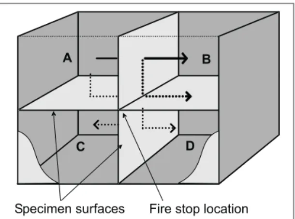
In all bu ild in gs, th ere is a d irect sou n d tran sm ission p ath th rou gh th e elem en ts th at are in ten d ed to sep arate on e sp ace from an oth er. In ad d ition , th ere are in d i-rect tran sm ission p ath s, or flan kin g p ath s, as sh ow n in Figu re 3. Th e d egree of acou stical p rivacy betw een d w ellin gs is d eterm in ed n ot on ly by d irect sou n d tran s-m ission th rou gh th e sep aratin g w all or
floor bu t also by th e in d irect flan kin g p ath s sh ow n above. In th is Up d ate w e refer to th e m easu red sou n d isolation , w h ere th ere is both a d irect p ath an d a series of flan k-in g p ath s, as bek-in g th e ap p aren t sou n d iso-lation . “Ap p aren t” refers to th e d egree of sou n d p rivacy exp erien ced by occu p an ts.
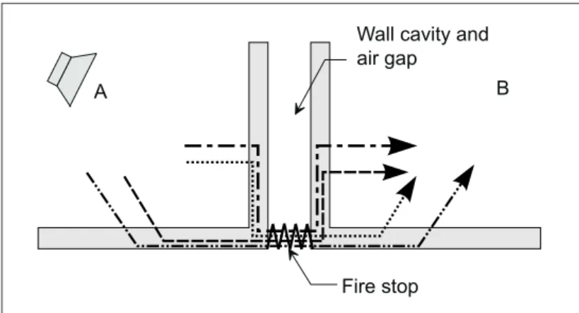
Rigid fire stop s at th e w all/ floor in tersec-tion in trod u ce a stru ctu ral con n ectersec-tion th at creates fou r ad d ition al flan kin g p ath s, on e of w h ich com p letely byp asses th e sep aratin g elem en t as sh ow n in Figu re 4. Th e acou stics p ortion of th e p roject exam in ed th e effect of fire-stop m aterials or tech n iqu es ap p lied at th e w all/ floor join t on th e sou n d isolation betw een th e room s “A” an d “B,” w h ich w ere sep arated by th e u p p er w all.
4 Construction Technology Update No. 16
Figure 3.Sketch of the IRC flanking transmission test facility showing the direct transmission path from Dwelling A to Dwelling B and some of the possible flanking paths
Fla nk ing Tra nsm ission
Th is term refers to th e tran sm ission of sou n d en ergy from on e room to an oth er by an y p ath oth er th an th e d irect p ath th rou gh th e sep arat-in g w all or floor.
Th e sim p le rep resen tation of a w all/ floor assem bly at th e left sh ow s th at flan kin g p ath s are in trod u ced w h en th e w all is con n ected to an oth er bu ild in g elem en t (e.g., a floor). In th is case, th e floor in trod u ces th ree flan kin g p ath s as in d icated by th e broken lin es.
Th e p h en om en on of flan kin g tran sm ission p ar-tially exp lain s w h y w alls an d floors tested in bu ild in gs u su ally exh ibit sign ifican tly w orse sou n d isolation th an th e id en tical on es m ea-su red in th e laboratory.
Th e sp ecim en u sed for th e system atic testin g of th e fire stop s w as typ ical of w ood -fram e con stru ction th at h as d ou ble w ood -stu d p artition w alls w ith a 25-m m gap betw een th e tw o sets of fram in g. Th e floor/ ceilin g assem blies w ere also of w ood -fram e con stru ction w ith a 25-m m gap betw een th e joist h ead ers.
Th e effect of variou s fire-stop m aterials on sou n d isolation w as d eterm in ed by com p arin g th e m easu red sou n d isolation both w ith an d w ith ou t th e fire stop in stalled . Th is ap p roach p erm itted an y ch an ge in th e m easu red sou n d isolation to be attribu ted to flan kin g p ath s in volvin g th e fire stop . It also allow ed each fire-stop m aterial to be 1) ran ked in term s of its acou stical effectiven ess an d 2) assign ed an ap p aren t sou n d -isolation ran ge, in d icatin g th e red u ction in sou n d isolation as a resu lt of th e fire stop . (Discu ssion of th e assign -m en t of a sou n d -isolation ran ge is beyon d th e scop e of th is Up d ate. See referen ce 2 for m ore in form ation .)
Group 0 Fire Stops — No Flanking Transmission
Ad d in g in su lation to th e cavity betw een th e tw o sets of stu d s so th at th e air gap is 25 m m or less does not introduce any flanking paths. In fact, th is ap p roach w ill actu ally h elp to im p rove th e sou n d isolation of th e w all (assu m in g th at th e w all h ad less cavity in su lation before th e ap p lication of th e fire-stop m eth od ) becau se, in th e absen ce of a p h ysical con n ection at th e w all/ floor
join t, all sou n d en ergy m u st p ass th rou gh th e w all cavity an d th e ad d ition al in su lation . (See box, “Flan kin g Tran sm ission ”). Strictly sp eakin g, th is ap p roach d oes n ot con stitu te a fire stop , bu t it m eets th e p rescrip tive requ irem en ts for fire sep aration s in th e NBC, Clau ses 3.1.11.2.(2)(d ) an d 9.10.15.2.(2)(a). Acou stically, th is is by far th e m ost effective m eth od of satisfyin g th e in ten t of th e NBC w ith resp ect to a fire stop .
Group 1 Fire Stops — Negligible Flanking Transmission
Th is grou p of fire stop s brid ges th e w all/ floor ju n ction w ith relatively soft m aterials, w h ich com p ress in resp on se to vibration , th u s tran sferrin g n egligible vibra-tion en ergy to th e oth er sid e of th e join t. Low -d en sity (48–80 kg/ m3) sem irigid m in
-eral fibre board s w ere fou n d to be acou sti-cally n eu tral sin ce n o sign ifican t stru ctu ral (rigid ) con n ection w as in trod u ced .
Alth ou gh th ese m aterials are n ot listed in th e NBC, th ey w ere tested in th e fire-resis-tan ce p ortion of th is p roject an d fou n d to be acou stically su p erior to th e con ven -tion al, listed fire-stop m aterials (i.e., OSB, p lyw ood an d sh eet steel).
Group 2 and Group 3 Fire Stops — Significant Flanking Transmission
For constructions with fire stops from Group 2 or Grou p 3, th e m ost sign ifican t flan kin g p ath d id n ot in volve th e p artition w all. Th e p ath th e sou n d took w as from th e “sou rce” room su bfloor to th e “receive” room su bfloor, via th e fire stop u n d er th e p artition w all. A d etailed an alysis of in d ivid u al flan kin g p ath s sh ow ed th at w ith a Grou p 3 fire stop , th e ap p aren t sou n d isolation m ay n ever be better th an STC 48, regard less of th e w all con stru ction . Th is fin d in g in d icates th at fire stop s form ed from con tin u ou s su rfaces th at go u n d er th e p artition w all (Grou p 3 fire stop s) sh ou ld be avoid ed w h en ever p ossible.
An STC 67 w all w as d egrad ed by 19 STC becau se th e tran sm ission p ath th rou gh th e con tin u ou s su bfloor (p lyw ood or OSB) fire stop p rovid es m u ch less resis-tan ce th an th e d irect p ath th rou gh th e w all.
Figure 4.Simplified cross-section through rooms A and B showing the four flanking paths introduced when a structural fire stop is installed at the wall/floor joint
Th e stu d y also sh ow ed th at th e effect of Grou p 3 fire stop s on th e ap p aren t sou n d isolation w as a fu n ction of th e floor con -stru ction — in p articu lar, th e orien tation of th e joists w ith resp ect to th e p artition w all. Sign ifican tly low er sou n d isolation w as fou n d w h en th e p artition w all w as n on -load -bearin g; i.e., w h en th e joists w ere p ar-allel to th e w all. Th is fin d in g is exp ected to h old tru e for Grou p 2 fire stop s as w ell.
Wh en a Grou p 3 fire stop w as in stalled , th ere w as n o ap p reciable d ifferen ce in th e sou n d isolation p erform an ce of p lyw ood an d OSB of th e sam e n om in al th ickn ess.
In all cases con sid ered , th e fire stop d id n ot affect th e sou n d isolation betw een ver-tically sep arated d w ellin gs (i.e., betw een room s A an d C, an d room s B an d D as sh ow n in Figu re 3).
Retrofit Techniques as Mitigation Measures Treatm en ts to th e floor w ere sh ow n to be very effective in con trollin g th e floor-to-floor flan kin g p ath s in trod u ced by Grou p 3 fire stop s. Wh en th e fin ish ed floor su rface w as n ot stru ctu rally con n ected to th e su b-floor (i.e., an en gin eered floatin g b-floor) in both th e sou rce an d receive room s, th e ap p aren t sou n d isolation in creased from STC 52 to STC 67, th e n om in al laboratory valu e of th e p artition w all. An altern ative, bu t less effective, ap p roach w as to ad d a 16-m m OSB overlay to th e su bfloor in each room (w ith th e sep aratin g w all alread y in p lace). Th is resu lted in variable im p rove-m en t, w h ich w as h igh ly d ep en d en t on th e con stru ction of th e w all.
Sum m a ry a nd Re c om m e nda t ions
Th e p roject d em on strated th at:
• Th e m eth od of fire stop p in g m u st be ch osen to reflect th e requ ired or d esired level of sou n d isolation betw een
d w ellin gs.
• Th e im p ortan ce of u sin g a system s ap p roach w h en bu ild in g w all/ floor assem blies th at m u st be both fire- an d sou n d -rated , w as d em on strated .
• Fire-stop m aterials an d m eth od s th at in trod u ce rigid stru ctu ral con n ection s betw een th e tw o row s of stu d s in th e cavity w all sh ou ld be avoid ed , w h en ever p ossible, esp ecially in th e form of con -tin u ou s su rfaces su ch as th e su bfloor. • Adding more cavity insulation to a
double-stu d w all so th at th e w id th of th e air gap is 25 m m or less is by far th e m ost effec-tive m eth od of satisfyin g th e in ten t of th e NBC from an acou stics p oin t of view. • Sem i-rigid fibre board m aterials (rock
fibre or glass fibre w ith a d en sity of betw een 47 an d 81 kg/ m3) w ere fou n d to
be acou stically n eu tral an d also satisfied th e in ten t of th e NBC (as in terp reted by th e con sortiu m steerin g com m ittee).
Th e vertical flam e sp read in th e w all cavity w as h igh ly d ep en d en t on :
• th e typ e of fram in g m em bers (w ood or steel)
• th e w id th of th e air gap • th e d egree of cavity ven tin g.
Dr. T.R.T. Nightinga leis a research officer in th e In d oor En viron m en t Program of th e N ation al Research Cou n cil’s In stitu te for Research in Con stru ction (IRC).
Dr. M.A . S ulta nis a sen ior research officer in th e Fire Risk Man agem en t Program of IRC.
1. Th e p roject w as su p p orted by a con sortiu m th at in clu d ed Can ad a Mortgage an d Hou sin g Corp oration (CMHC); Forin tek Can ad a Corp oration ; Gyp su m Man u factu rers of Can ad a (GMC); In stitu te for Research in Con stru ction , Nation al Research Cou n cil Can ad a; New Hom e Warran ty Program s of On tario, Alberta, British Colu m bia an d Yu kon ; On tario Min istry of Hou sin g; Ow en s Corn in g Fiberglas Can ad a In c.; an d Roxu l In c. In d ivid u als from th ese organ i-zation s form ed a steerin g com m ittee.
2. Nigh tin gale, T.R.T. an d Halliw ell, R.E.H., Flan kin g tran sm is-sion at join ts in m u ltifam ily d w ellin gs. Ph ase I: Effects of Fire Stop s at Floor/ Wall Join ts, In stitu te for Research in Con stru ction , Nation al Research Cou n cil, In tern al Rep ort 754, Decem ber 1997.
3. Su ltan , M.A., Segu in , Y.P., an d Lerou x, P., Fire Perform an ce of Fire Stop s in Mu lti-Fam ily Dw ellin gs, (in p rep aration ), In stitu te for Research in Con stru ction , Nation al Research Cou n cil, 1998.
“Construction Te chnology Up d a te s” is a se rie s of te chnica l a rticle s conta ining p ra ctica l inform a tion d istille d from re ce nt construction re se a rch.
For more information, contact Institute for Research in Construction, National Research Council of Canada, Ottaw a K1A 0R6
Telephone: (613) 993-2607; Facsimile: (613) 952-7673; Internet: http://irc.nrc-cnrc.gc.ca
© 1998
Nation al Research Cou n cil of Can ad a Ju ly 1998