Publisher’s version / Version de l'éditeur:
Vous avez des questions? Nous pouvons vous aider. Pour communiquer directement avec un auteur, consultez la première page de la revue dans laquelle son article a été publié afin de trouver ses coordonnées. Si vous n’arrivez pas à les repérer, communiquez avec nous à [email protected].
Questions? Contact the NRC Publications Archive team at
[email protected]. If you wish to email the authors directly, please see the first page of the publication for their contact information.
https://publications-cnrc.canada.ca/fra/droits
L’accès à ce site Web et l’utilisation de son contenu sont assujettis aux conditions présentées dans le site
LISEZ CES CONDITIONS ATTENTIVEMENT AVANT D’UTILISER CE SITE WEB.
Internal Report (National Research Council of Canada. Institute for Research in Construction), 1998-06-01
READ THESE TERMS AND CONDITIONS CAREFULLY BEFORE USING THIS WEBSITE. https://nrc-publications.canada.ca/eng/copyright
NRC Publications Archive Record / Notice des Archives des publications du CNRC : https://nrc-publications.canada.ca/eng/view/object/?id=fc3ff0d8-1d53-4977-b698-76136707772a https://publications-cnrc.canada.ca/fra/voir/objet/?id=fc3ff0d8-1d53-4977-b698-76136707772a
NRC Publications Archive
Archives des publications du CNRC
For the publisher’s version, please access the DOI link below./ Pour consulter la version de l’éditeur, utilisez le lien DOI ci-dessous.
https://doi.org/10.4224/20331289
Access and use of this website and the material on it are subject to the Terms and Conditions set forth at
Evaluation of Thermoplastic Olefin (TPO) Roofing Membranes
http://irc.nrc-cnrc.gc.ca
Eva luat ion of T he r m opla st ic Ole fin (T PO)
Roofing M e m bra ne s
S i m m o n s , T . R . ; P a r o l i , R . M . ; L i u ,
K . K . Y . ; D e l g a d o , A . H . ; I r w i n , J . D .
I R C - I R - 7 6 8
June 1998
EVALUATION
OF
THERMOPLASTIC OLEFIN
( P O )
ROOFING MEMBRANES
ABSTRACT: As part of a five-year investigation, rnechanicd (strength and elongation)
and chemical (thermogravimetry and dynamic mechanical analysis) methods of
evaluation are used in this paper to characterize in-service thermoplastic olefin (TPQ)
roof membranes. AIF the nun-reinforced membranes meet the minimum thickness and
tensile strength requirement as specified in the proposed ASTM standard. The poIyester scrim reinforced membranes were superior in tensile strength and elongation as compared
to those reinforced with random mat of short glass fibers. The standard should consider
defining the breaking strength in terms of "stress" instead of load, This would allow for a
fairer and easier comparison of strength between reinforced and zlnreinforced TPOs. Also,
the term TPO is confusing and very vague. The standard should consider differentiating
the different types
of
TPOs. Basedon
themogravimetry, at least four different types of TPOs are currently in service. Also, the standard should consider using the glass transition temperature to monitor agingweatbering of membranes.KEYWORDS:
roofing membrane, single-ply roofing, thermoplastic olefin,thermoplastic poly~lefin, TPO, poIyethylene, polypropylene, flexible polyolefin,
P O ,
flexible polyolefin alloy, P A , FTO-A, glass-transition temperature, Tg, dynamicmechanical analysis, DMA, thermal analysis, themogravimetry
1. Introduction
TPO
roof membranes have been in service in Europe for approximately 10 yearsmd the use of this
family
of membranes in North America is increasing. As is expectedwith
any
new material entering the market, therehas
been a learningcurve associated
with the installation and maintenance of TPOk. Also, little information is available to the
general public r e g d i n g their durabiIity.
The objective of this study is to investigate the long-term performance of in-
service thermoplastic olefin or polyolefin (TPO) roofing membranes. A range
of T O
membranes with different reinforcements, weave styEes and polymers is covered. ms
paper
is
the first part of the study. It focuses on the mechanical (specifically the tensile strength and elongation) and chemical (themogravirnetry and dynamic mechanicalanalysis) properties of the year-0 membranes. The techniques used in this study were
chosen because they
allow
users to see changes, ifany,
in the material over time. Theresults will form a baseline for the weathered membranes to be compared against in the
subsequent stages.
1.1 Background
Thermoplastic olefin or polyolefin (TPO) membranes have been available and in-
use for several years. The focus of this paper will be TPO products available in the United
States. At first, only n couple manufacturers produced a hand-full of products. Within the
last few years, other manufacturers have come on-line with new product offerings.
IRC-IR-768 Evaluation of Thern~oplastic Olefin (TPO) Roofirlg Membranes
There are essentially two classes of polymer-based
roofing
membranes,rhemzosets ('I3) and thermoplastics (TI'). Thermosets include EPDM, chIorosrrlphonated
polyethylene (CSPE) and neoprene, Thermoplastics include a wider variety of systems
such as TPO's, poly[vinyl chloride],
(PVC);
ketone ethylene esterW E ) ,
etc. Allthermoplastics share some
of
the same characteristics, e-g., heat-weldable. However, theyhave very different chemical and physicaVmechanica1 properties.
It is beyond the scope
of this paper to explain these differences but suffice it to say that there are different ASTM material-based standards for variousTP
products. To avoid confusion, one should not justlabel dl of these products simply as
TP
products as TPO's are not PVC's or KEE's.The term olefin i s an old chemical name for any molecule contaidng carbon-
carbon double bonds. The modern name for
this
family of molecules is alkenes. According to the ASTM proposed IT0 standard, the composition is very non-specific.There
are
two types of TPO's; Type 1 contains morethan
95% (mass percent) TFOpolymer; and, Type 2 contains between 50 and 95% ((mass percenlt) TPO polymer. The
polymer itself is
not
defined within the standard.AIE
thatis
stated is the sheetshall
contain the "appropriate" polymers. Using this definition in combination with the definition of olefin, there is an endless list of chemicals which would fit in this standard
(e.g., polyethylene, polypropylene, isobutyIene, etc., as well as their derivatives) There are a few papers written
on
TPO's which explain the different types of TPO's [I-43.UnfortunateIy, they do not provide specific details on the chemical composition
(although, reference 3 does menti on that acetates, acry lates or octenes are blended together). In fact, these references are somewhat confusing because of the terminology they
use.
It is known that thereare
two processes;one
includespo1yethyIene-based
alloys(FPO-A) [1,3] while the other process known
as
"Catalley" includes polypmpylene-based alloys (FPA) [Z]. Moreover, it is not known if FPA is alloyed with polyethylene nor ifFPO-A is alloyed with polypropylene. Manufacturers of either system report similar
mechanical and chemical properties. However, to date, there is insufficient information to determine the durability of the two types.
TPO membranes, in general, have the potentid to fulfill many of the reqvirements
that are desirable in the roofing
rnarketpIace.
The following benefits have been repoaed for TPO's [I-31: they are environmentally friendly, recyclable, welded seams as opposedto adhesives, and no external plasticizers added to the compounding.
I.I.1 Field Observations
The last several years have provided insight into the application of TPO
membranes. What became apparent immediately was that the TPO membranes do nut
have the same feel (e.g. flexibility, texture, etc.), handling, and application as the other thermoplastEc membranes
on
the market.The
TPO membrane" weight is relatively lessthan some other comparable products. While flexible, the TPO membrane has a rather
rigid feel. The
TPO
membrane has a tendency to hold its shape, and doesnot
relax quickly. The initial feedback from applicators in the field brought forth the foIIowingattributes of
TPO
membranes:*
Hot-air weld seams are easierleleanerthan
adhesive-based seams; Material is not as heavy (i,e., weight) so it is easier to handle;IRC-IR-768 Evalrratinn of Thernt onlastic Oldin f TPO 1 Roofirla Menthrones
Lower cost than some other hot-air welded membranes;
Mechanically fastened systems work well in recover applications;
Non-reinforced membrane is easy to form for detailing;
Cold welds frequentIy occur; the start and stop positions of the robotic welder arc especially critical, as well as t-seams;
N m o w welding window between coId welds and scorchhurn-through; Stiff membrane that does not relax well;
Failure of bonding adhesive which will not stick to the membrane;
Noticeable changes in look (color variance) and feel of membrane (texturelfmish), as
manufactured, over time;
Membrane, at times, requires soIvent wipe before welding;
Black membranes are more difficult to weld than white membranes;
Black membranes are hot to the touch after exposure to the sun;
Membrane caulk a problem; on hot days caulk would be runny;
Cigarettes burn holes in membrane easily, noted to be more severe than other
themeplastic membranes;
Problems with re-welding membrane after exposure to sun to make repairs.
In
consideration of these attributes one could say that TPO membranes are not'tontractor-friendIy." Some of these items may be attributed to the natural learning curve associated with new products, however, for some applicators, ease and satisfaction with the TPO membranes has yet to reach a comfort level.
Aside from the installation issues, there nre what appear to be performance issues as well. Some of the potentially problematic performance attributes that have been
observed include:
Cold welds frequentIy occur resulting in seam voids that leak; Burn-through of membrane during welding results in voids; Failure of bonding adhesive, flashing membranes delaminate/sag;
Color change noted in light-colored
membranes after exposure
tosun;
Cigarettes burn holes
in
membrane easiIy
-
roof-topusers not
respectful of membrane;
Problems with re-welding membrane after exposure to sun to make repairs.
In
someinstances, adhesive was
required
to makerepairs,
The first appearance of a "TPO-type" roofing product in the W.S. was in ca. 1987
13.
Three products, offered by one company, were listed in Ithe EPDM section of the NRCA Roofing Materials Guide [5].The
pmduct literature listed the membrane as being a thermoplastic elastomer (TPE) madefrom
50%EPDM
polymer (froma
proprietary source) which is fully cross-linked and suspended in a polypropylene matrix in a processhewn as dynamic vulcanization. h the generic classification of thermoplastic
elastomers, the manufacturer reports that the proprietary EPDM polymer is considered
okfinic. The membrane reportedly contained ne fillers or plasticizers.
The
seams were heat-fused[a.
A version of this product (from another supplier)remained on the
marketuntil late 1990, when the company and Ithe product reportedly left the market.
IRC-IR-768 Eval~iarion of Thern~oplasfic Olefin ( P O ) Roofing Membranes
h 1991, another company with a new product entered the market that reportedly had the benefits of EPDM and hot air weIded
seams.
The product literature listed themembrane as being EP elastomeric, thermoplastic alloy (ETA), containing no plasticizer
[q.
The membrane was reported to be an EP rubber (ethylene propylene), with the unique alloy being 100% polymer 181.h
1993, still another company introduced a new product that has theweatherability of rubber with the heat weldability s f a thermoplastic [PI. Listed as an ethylene propylene rubber ('EP), "the base product is made
by
a two-phase, in-reactorpolymerization
of
monomers with a very specific catalyst. The elastomer phase is a non- vulcanized ethylene propylene which imparts the compound with flexibility and Iow temperature properties. The olefin phase imparts chemical resistance, tear resistance, and enhanced strength to the blend, and enables the product to be heat welded"[IO].
The most current thermoplastic alefin into the market appeared in 1996 with an
ethylene propylene rubber
(EPR)
formulation [ I 11.
1.1.3. Marketplace ConfmionThe marketing
of this
new generation ofP O
membranes has greatly focused onthe EPDM-lik characteristics of being rubber with the benefits of welded seams. Another focus has been on the chemical resistance attributed to the olefin side of the
polymers. Unfortunately,
some
confusion in the market place has occurred, especiallyregarding the use of the term rhermoplastic (TP). It is important to remember that
TPOs
are
themopIastic (i.e., TPs)but
not all TPs are WOs. Same marketers ofthermoplastic non-TPO single-ply membranes (e. g., blends and alloys) market their
product as
TP
without specifying, for example, if they are KEE- or PVC-based.2. Experimental
Ten
membrane samples, (eight reinforced and two non-reinforced) were selected(see
Table 1). Out of the eight reinforced samples,three
came with seams. Figure 1 shows the seam (S), field 1 (FI) and field 2(F2)
locationsfor these
membranes (J02-Sol-MI,J02-S02-MI and J09-SO1
-OK).
Figure 1 Definition of dinerent regions in a membrane sample with a seam.
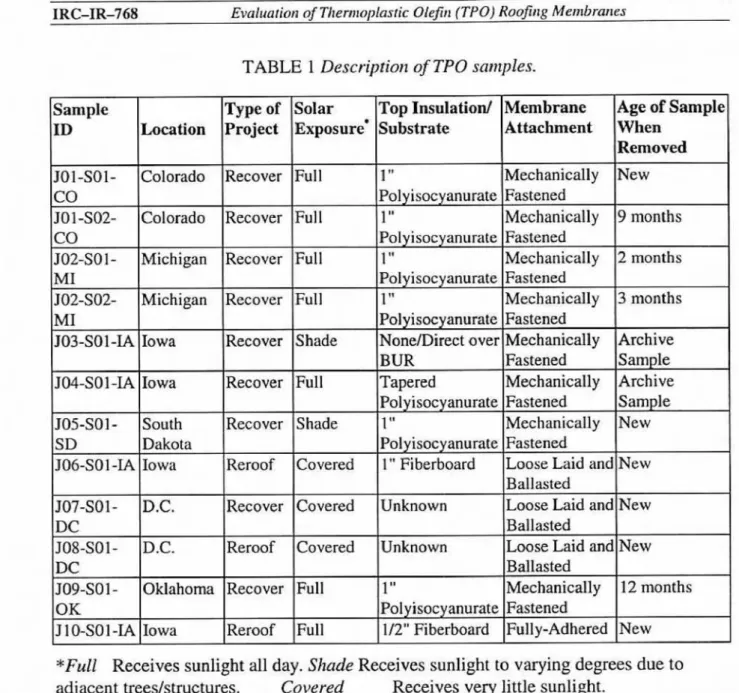
TABLE 1 Description of TPO sulnples.
*Full Receives sunlight all day. Shade Receives sunlight to varying degrees due to
adjacent trees/structures. Covered Receives very little sunlight. Note: The slope on all projects was noted to be 114" per foot or Iess.
The machine and
cross
directions were not marked on the membranes. Seam lines and batch Iabels were used to determine these directions. However,no
distinguished marks were foundon
membranes J03-SO 1 -&I, SO6-Sol-IA and J07-SO1 -DC, thus thedirections were assigned arbitrarily. Specimens were taken in both the machine and cross
directions. When there was a lack of membrane, priority was given to specimens in the machine direction.
Visual examination indicated that the =inforced sanzpIes consisted of fiber
reinforcements bonded in different weave styles and sandwiched in several types of TPO
sheets. A summary of the components in the membranes is shown in Table 2.
2.2 Tension Testing of M e ~ n bmne Satnples
2.2.1 Specimen Preparation
Although method A (grab test method) of ASTM
D751
was specified (in theproposed TPO
standard)
to test the reinforced samples, the limitedamounts
ofsome
ofthe samples were not sufficient to prepare the necessay number of replicate specimens.
To
ensure a good sample size in these sampIes and to provide a good comparison between the membranes, the optional method B (cut strip method) was used,A hydraulic die press was used to cut dumbbell shaped specimens from the non-
reinforced membranes using die C as specified in ASTM D412. Ten specimens were
prepared in each of the machine and cmss directions for each test temperature. The
thickness of each specimen was measured, taking an average of five points measured
along the length of the specimen, using a digital micrometer.
TABLE 2 Summary of the cotnpanents in the TPO roofing membranes.
N/A Not Applicable C1 Yellowish brown coating
NC Not Coated
C2 Clear coating
Strip specimens were cut fiom the reinforced
membrane
using a knife. Thedimensions
of the strips were as specified in ASTM D751 Method B. A minimum of five specimenswas, where possible, prepared in the machine direction (and where possible, also in the cross-machine direction) for each test temperature. The thickness af the specimens
was
measured using a digital micrometer. The width of the specimens was measured using a
digital calliper, taking an average
of
five points along the length of the specimen.AII samples were tested using an hstron 4502 Automated Materials Testing System. The room was kept at a constant temperature of 23
+
2 "C and a relativehumidity of 50 f 5%. Pneumatic grips were used for the non-reinforced specimens while
hydraulic grips were used for the reinforced specimens at room temperature. However,
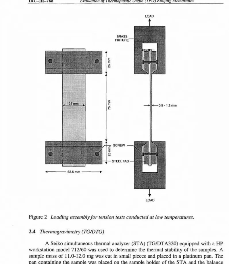
the grips could not be used for low temperature testing. Instead, as shown in
Fig.
2, the specimen ends were sandwiched between apair
of specially designed tabs that could be tightenedwith
a screws.This
entire assembly was slid into the accompanying fixturemounted on the testing machine. An Instrwn environmental chamber was used
for
testsconducted at -40°C
2
3 "C.The non-reinforced specimens were tested at a constant crosshead speed of 500
rnmlmin using a I-kN capacity load cell.
The
gage length was 25 mm. The reinforced specimens were tested at a constant crosshead speed of 300 r n d r k n using a 10-kNcapacity load cell. The gage length was 75 mrn. Specimen ends were also folded in the
grips to prevent reinforcement slippage during testing (Figure 2).
An hsmn
XE
'Extensiometer was used to measure elongation of the non-reinforcedspecimens at room temperature. However, crosshead displacement was used to
approximate the specimen dongation at -4U°C due to limited space in the environmental
chamber. Crosshead displacement was
also
used to measure elongation of the reinforced membranes at both test temperatures, The load and elongation data were recorded by adata acquisition system. The sampling rates were 25 and 50 points per second for the
room temperature and the cold ternperature tests, respectiveIy.
2.3 Dynamic mechaaicul analysis
@MA)
A Rheometrics Solid Analyzer RSAII equipped with a control computer, a
mechanical cooler and environment controller was used to measure the glass transition
temperature of the samples.
Two
rectangular strips were cut from the "%is received"'samples (A and B), placed an the dual cantilever fixture and coaled to -70 "C. After
allowing the temperature to stabilized for about 1 minute, the temperature program was
started. The samples were run in duplicate. Test type, dimensions of the specimens and
experirnen tal parameters are summarized below.
Geometry: Specimen dimensions: T a t Frequency: Temperature range: Ramp rate: Soak time:
Time pet measurement: Strain:
Auto Tension Adjustment:
Au tostrain:
Dual cantilever
Length: 36.6 mm (fixed)
Width: 4.9 mrn
-
5-5 rnm Thickness: 1.0 mm-
1.3mm
Dynamic temperature ramp 1
Hz
(6.28 radlsec)-70 'C to +30 or +I0 "C
2 "Clmin
30 sec
60
sec0.02-0.2% (depending
on
the specimen) OFFOFF
XRC-IR-768 Evaluation of Tltennopfastic Oleifin (TPQ) Roofirrg Membraria~ LOAD 4 SCREW - . STEELTAB
+
LOADFigure
2
Loading assembly for rension tests conducted at low temperatures.A Seiko simultaneous thermal analyzes (STA) (TGDTA320) equipped with a
HP
workstation model 712160 was used to determine the thermal stability of the samples. A sample mass of
E
1.0-12.0 mg was cut i n small pieces and placed in a pla~nurn pan. Thepan containing the sample was placed on the sample holder of the STA and the balance
was allowed ea stabilize before starting the program. The temperature was increased at a
rate of 20 "Urnin, from room temperature to 1000 "C using 150 mL,min of ultra high
purity nitrogen.
IRC-IR-768 Evaiuarion of ThermopEasfic Olefin (TPO) Roofing Membranes
3. Results
Typical force-displacement curves of the membranes are shown in Figures 3-4.
The non-reinforced specimens (Figures 3 - 4) behaved in an elastic manner at 23°C. They
yielded and stretched extensively before they finally broke. At
-40°C,
503-501-IA becamebrittle. The specimens yielded and necked, and broke with little stretching
(Figure
3).On
the other hand, JWSO 1-IA
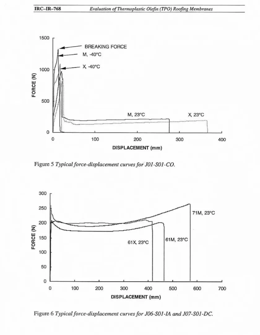
yieIded and stretched substantially before failure (Figure 4).For
the specimens reinforced with continuous polyester fibers (J01,502,J05,
J08,
J09 & JIO), the load went through a peak and a sudden drop before reaching a plateau which was about 15 - 20% of the maximum load (an example,
JO
1301-CO, is shown inFigure 5). Except for J08-SO1-DC which was relatively brittle, all samples behaved elastically at 23°C with yielding and stretching exceeding 300%. They became brittle at -
40°C and broke cleanly cross the width with stretching not exceeding 30%.
For the specimens reinforced with random short glass fibers mat (506-501-IA and
J07-SDl-DCS, the
load
also went through a peak, a load dropand
reached a plateau(Figure 6 ) . The load drop (5 - 10%) was not significant compared to that of the sarnpIes
reinforced with continuous polyester fibers (80 - 85%).
In
addition, the force increasedagain
before
final failure.The tensile strength and the ultimate elongation of the non-reinforced membranes were determined. The tensile strength is defined as the maximum tensile force divided by
the cross-sectional area (i-e., width x thickness)
of
the specimenwhile
the ultimate elongation is the ratio between the final gage separation and the initid gage Iength inpercentage as measured by the extensiorneter. For the reinforced specimens, the breaking
strength and the elongation at break were determined. The breaking strength is defined as
the breaking force of the reinforcement divided by the cross-sectional area while the elongation at break is the ratio between the gage separation at break and the initial gage length in percentage. Note that the breaking strength
in this paper
is definedin
terms ofstress instead of h a d as In the standard. This definition eliminates effect of the difference
in thickness variation of the non-reinforced
membranes. These
parmeters
are labelled in Figures 3and
5. The mechanical properties are summarized in Tables 3 and 4 and are plotted in Figures 7 and 8. The membranes were listed in orderof
decreasing elongationat the two test temperatures (Table 5).
MAXIMUM
0 50 1Q3 150 200 250 300
DISPLACEMENT (mm)
Figure 3 Typical force-displacenaen f curves for J03-SO J-IA.
0 50 100 150 200 250 300
DISPLACEMENT (mm)
Figure 4 Typical force -displacement curves for J#-,901 -IA.
IRC-IR-768 Evahation of Thermop!astic Olejin (TPO) Roofing Membranes 100 200 300 DESPLACE~MIENT (mm) BREAKING FORCE M, -40°C M, 23°C y 23°C
Figure 5 Typical force-dkp Lacement curves for 'JOI -501
-GO.
. . -u_---.I I 0 0 100 200 300 4M) 500 600 700 DISPLACEMENT (mm)
-
-.
!
It
IFigure 6 Typical force-displacement curves for
JM-SO1
-]A and JQ7-SO1-DC.
'FABLE 3 Mechanical properties of rhe non-reinforced
TF
0
roofirag membranes.For the non-reinforced specimens, the proposed ASTM specification requires a
minimum thickness far the overall sheet of 1.0 mm. It also specifies a minimum tensile strength and ultimate elongation of 12.0 MPa and 500%, respectively at 23 "C. All of the
samples meet the minimum thickness, elongation and tensile strength requirements at this temperature.
Membrane J03-SOI-IA performed better than JM-Sol-IA at room temperahre,
with higher
smngt'h
and elongation(Figures
7-
8). At40°C,
thetensile strength
ofboth
membranes doubled.
J03-Sol-IA
became very brittIe with its elongation dropping toalmost zero - a drop of more than
100 times
from its room temperature value. On the other hand,JM-Sol-IA
remained relatively ductile at 4 0 ° C and the elongation droppedby about 30% only.
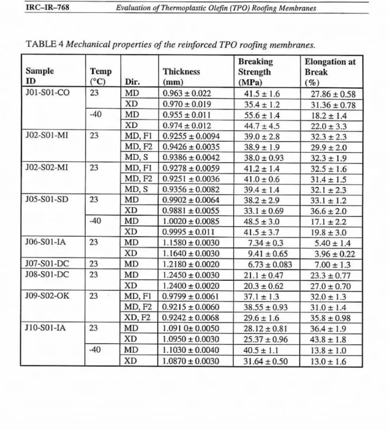
For the reinforced membrane samples, the draft ASTM specification requires a
minimum thickness for the overaIl sheet of 1.0 rnrn. Only membranes J06-S01-IA, JOT-
Sol-DC, 908-Sol-DC and J10-Sol-IA meet that specification. The mernbranes reinforced
with the polyester
scrims
had better strengthand elangation
values
than thosereinforced
with
random
short
glass fibermat
(JOG-Sol-IA and JO7-Sol-DC)as
expected.T h e
breaking strength of the random short glass fibers reinforced membranes was less than 10MPa while that of the pdyester scrims reinforced
ones
ranged from 20 to 45 m a at 23OC(Figure 7). The elongation at break was less than 10% for the short fiber glass mat reinforced membranes but that of the polyester scrim reinforced ones was at least 20% at
23°C pigure 8).
TABLE 4 Mechanical properties of the re irxforced TPO roofing membranes.
p u p 9 9
n r r
s ppi;;
d d D d d ;--
IRC-IR-768 Evaluation of Thermoplastic Olefln {TPO) RoofSng Membranes
ULTIMATE ELONGATION
I
ELONGATION AT
BREAK
(%)
Figure 8 Ultimate elongation Iclongation at
break
of the TPO roofing membranes.IRC-R-768 EvaIua r ion of Themoplasric OlejTn (TPO) Rooflng Membranes
TABLE 5 Listing of TPO membranes irz order of decreasing elongafion af diflererrt resr
temperatures.
The polyester scrim reinforced membranes were stronger (10 -
30%)
in themachine than in the cross direction at both test temperatures. The elongation at break in
the cross direction was at least
as
high as in the machine direction.On
the other hand, therandom short glass fiber reinforced membrane JOB-Sol-IA was stronger in the cross than
in the machine direction. The elongation at break was the same for both directions. At -40°C, the increase in the breaking strength of the polyester scrim reinforced membranes
and the decrease in elongation were statistically significant.
-..--..--- I 3.
Three types of polyester reinforcements were used in these membranes, nameIy, a
coated scrim in a plain weave style, an uncoated scrim with intersecting tows held together by fine polyester fibers and a coated scrim in undetermined weave style (Table 2). The membranes reinforced with the coated scrim i n plain weave
(JOI,
J02,J05
andJ09)
were the strongest with breaking strengths of at least 30 MPa. The membranesreinforced
with
the uncoated scrim with intersecting tows held together by fine polyesterfibers
(JIO-Sol-Lk)
had a breaking strength ofaround
27 MPa. The weakest of the t h etypes was the membrane reinforced with the coated scrim (J08-Sol-DC) which had n
breaking strength of 20 ma.
JOS-SO 1-SD
J09-Sol-OK
- - - " " * - - -
J08-Sol-DC
- - - 2 - . . . - - . - m - - - L . . - - -
After the reinforcement broke
(break
point), the tensile load was taken up by thepolymer matrix only. The polymer stretched and thinned down a great deal before final
failure at 2 3 T . The ultimate elongation, as defined by the ratio between the final and the
initid grip distances, is a measure of stretching ability of the polymer matrix. This
property can
be
approximatedby
the maximum displacement an the force-displacementcurves divided by the initial grip distance of 35
mm.
The ultimate elongation of the TPQused in the short glass fiber reinforced membranes (506 and 107) was especially high in
the machine direction [over 600%). However, the same colored TPO used in the
membrane J08-Sol-DC had
an ultimate
elongation of about 30%. It is interesting tonote
that the plateau region of the force-displacement curves was roughly between 100-
200 Nor about 4
-
8 MPa for every membrane tesfed at 23OC.IRC-Building Envelope Program Roofing Sub-Program Page 16
4. J06-Sol-IA
All membranes but the polyester
scrim
reinforcedmembrane J1OSO1-LA
failed ina similar manner in both the machine and cross directions. Unlike the others, when
membrane J10-Sol-IA was stressed in the machine direction, small holes started to
develop on the white polymer sheet at the intersection of the perpendicular tows after the
fiber tows in the loading direction broke. More holes were developed as the specimen was
stretched. Those located along the fiber tows in the cross direction coalesced until the
white polymer sheet broke across the specimen width,
The
fiber tows in the crossdirection, then exposed, started to unravel and finally fell off the polymer sheet. At this point, the black poIymer sheet, which was usually still intact, continued to stretch and separated the white polymer sheet into small pieces. The specimen stretched and thinned down to a high degree
such
that it resembled a snakeskin. In the cross direction, thepolymer did not stretch as much after the fibers tows in the loading direction broke. The
polymer sheets findly broke and the polyester scrim delaminated almost completely h r n
the polymer sheets.
3.3 Dynamic mechanical analysis (DMA)
A typical DMA plot is shown in Figure 9. The
T,,
measured at a frequency of 1Hz, was obtained from the intercept of two tangents on the storage moduIus (E') and the maximum of loss rnoduIus (E"). The glass transition for all samples ranged from 4 6 "C
to -42 "C using E' and
-37
"C to -32 "C usingE".
The only exception was J04-SO1-W,
which showed a T, of -58
"C
and-54
"C from the E ' Eand ~E",,, ~ ~respectively ~ ~ (seeTable 6).
$ (Bottom)
IO3-SO1IA JWS01-IA
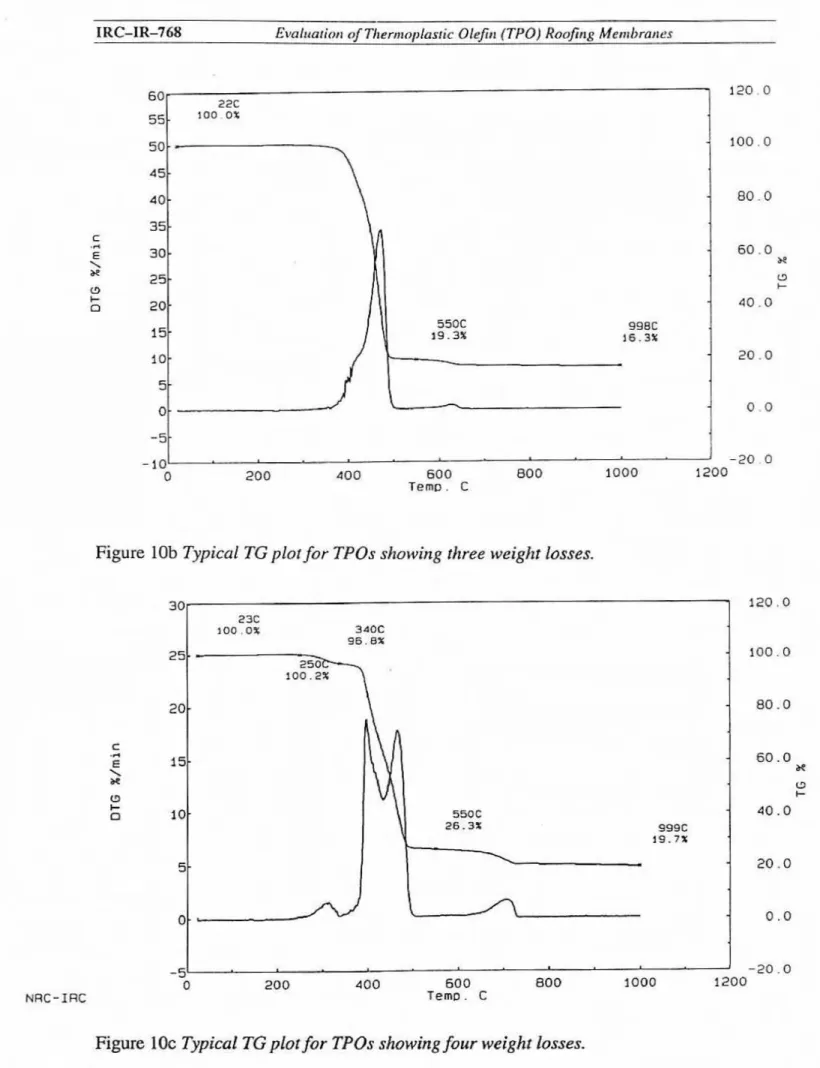
The samples show from one to four weight losses in
the
full
temperaturerange
ofanalysis (see Table 73. Some display a small weight loss (4%) in the 25 - 340 "C region. This may be due to the loss of stabilizers. The second weight loss (6595%). resulting
fmm
the polymer decomposition is not completely resolved for some of the samples. Thisweight loss shows two DTG maxima. One between 330 "C and 430 "C and the other JOS-SO 1 -DC
J09-SO1-OK
J 10-Sol-IA
IRC-Building Envelope Program Roofing Sub-program Page 17
5.05 5.15 5.11 5.14
1
0.79 1.26 1.10 1.26 0.1 I 0.06 0.05 5 . 2 0 11.09 5.401
1.07 0.2 -44 4 2 -5 8 (4.06 0.08 4 4 -37 -34 -54 -32 -44 -- --42 I ' -35 -37I R C - W 6 8 EvaCuarion of ThcrrnopIrastic Olefin (TPOJ Roofing Membranes
TABLE
7a One main weight loss.TABLE 7b Two resolved w e i g h losses.
TABLE 7c. Three (one resolved and two unresolved) weights losses. Sample
m
JWSO1-IA JOS-Sol-DC
' ~ o t e : the 340 to 1000 OC region confains two distinct but unresolved weight losses
TABLE 7d Four (two resolved and
two
unremlved] weight losses. WeightLoss
% Residue Sample LD 25-340 "C 340-550 OC* 550-1000 OC % JOISO1-CO 2.8 70.0 7.6 19.6 JOI-SOZCO(F1) 3.2 70.8 6.9 19.2 S (Bottom) 2.8 71.7 7.3 1 18.2 JO5-SOI-SD 2.8 70.0 8.1 19.2 Weight Loss YQ*NOW: the 340 to 550
"C
region contains two distinct but unresolved weight lossesResidae
947
IRC-Building Envelope Program Roofing Sub-program Page 18
I 25-417 "C 33.2
-
25-340 "C --- 8.2 417-550 "C 60.2 -- 340-1000 "C 550-1000 "C-
66.2 1 .Q 5.6 25.6I R C-I R-768 El~uiualio~ of Tllernmplas~ic OIejir~ (TPO) Rnojirlg Mernbrarr es
Figure
9
Typical DMA plot for TPOs.Figure 10a Typical
TG
plot fir TPOs s b w i n g one main weight loss.1 R C-I R-768 E ~ ~ a h t a r i o ~ of Tlrern~nplastic OleJt~ (TPO) R o o m MentBmtrcx
NRC-IRC
Figure lob Typical TG plotfor TPOs showing three weight losses.
I 1 -20.0
-51
0 200 4 0 0 50 0 BOO 1000 1206
T e m p . C
Figure
10c Typical TG piorfor TPOs showing four weight Eassex.PRC-IR-768 Evaluation of T!termoplas~ic Olefin (TPO) Roolfing Men1 bmmes
between 430 "C and 600 ' C , except for J03-SOI-IA and J08-S01-DC samples, which
shows only one weight loss between 340 "C and 600 "C. The third weight loss (1-8%) occurs in the 600-4000
"C
region. For those that underwent two weight losses, theyoccurred in the 25 - 417 'C (33%) and 417-600 "C regions (61%). Typical plots nse
shown in Figure 10.
4. Discussion
For the non-reinforced membranes tested at -40°C, J03-Sol-LA was 30% stronger
than JW-SOI-IA, but had almost no ductiIity (Figure 3). The strain energy of J03-S01-IA
(the area under the force-displacement curve) is low. On the other hand, the swain energy remained high for membrane J04-301-L4 at -40°C (Figure 41, perhaps making it more suitable than 503-501
-L4
far cold temperature applications.As expected, the membranes reinforced with continuous
fibers
had higherbreaking strength than those reinforced with random short fiber mat. The
membranes
reinforced with the coated scrim in plain weave style were stronger than those reinforced
with the other two polyester scrims. To find out if the difference in strength was due to
the difference in reinforcement strength or the
amount
of reinforcement present indifferent weave styles, the number of fiber tows across the width of the specimen was determined. The strength per fiber tow was found to be roughly the same (Table 8). As a result, the variations in the breaking strength were due to the difference in weave style.
TABLE 8 Determination of
rhe
strengfh per$bcr fow. Number ofBreaking tows across Strength per
Reinforcement Strength width of fiber tow
Types Membranes (MI%) specimen (MPa)
JO 1 -SO 1 -CO
Coated (yellow) scrim J02-501-MI
J02-S02-MI 36+5
9-
10 3.8+
0.5in plain weave style
JO5-Sol-SD
J09-SO 1 -OK Uncoated scrim with
intersecting tows held
B
1 O-SO1 -1Atogether by fine
polyester fibers
Coated (clear) scrim of
undetemi ned weave
IRC-IR-768 Evaluation of Themsplosric Ole fin (TPO) Roefinn Membranes
TOP VIEW
$prnVrn?%
... ^ ..&. k.. ... ..::: .... :=::-- - .. ....END VIEW OF MD
Figure 1 1 Deformation of the reirf~rcerneaC sbr~ciure during l'ensil e testing of membrane JIO-$01-IA.
The difference in
weave style hadan
effkct on how a membrane failed as well.510-Sol-IA
was reinforced with an uncoated scrim where the intersecting tows were heIdtogether by fine, continuous polyester fibers
(Figure
11). When the membrane was pulledin the machine dimtion, the fine fikrs stretched and tightly held onto the tows in the
cross direction. This created high localized stresses at the intersections. As a result, holes
were
initiated atthese points. They
coalesced as the stress increased and h emembrane
failed.
On
the other hand, when the membrane was stressed in the cross direction, nolocalized stress points were formed
since
the fine fibers held the tows in the machinedirection by sandwiching instead of pulling them.
For the spechens reinforced with continuous polyester fibers, except membrane
J08, the load first went through a peak and a sudden drop, which corresponded to the
breaking
of
thereinforcement, The
load then reached a plateau, which corresponded to the combined effmts of reinforcement sliding at the fiber-matrix interface and matrixstretching. It is interesting to note that the load at the plateau region of the force- displacement curves was between 100 - 200 N, or about 4 - 8 ma, for every membrane,
continuous fibers or short fibers alike, tested at 23OC. Since reinforcement sliding should be a function of interfacial adhesions and reinforcement structure, this constant
force
in the plateau region indicated that the effect s f matrix stretching is dominant.The breaking strength of the polyester scrim reinforced membranes increased by about 20
-
30% as the test temperature dropped to-40°C.
However, themembrane
became brittle and the ultimate dongation (Figure 5 ) reduced more than 15 times. Since
IRC-ZR-368 Evaluation of Themnplasfic Olefit1 (TP 0) Roof~rrg Mer~lbranes
the ductility of the matrix governs that of the membrane, it is recommended that polymers with superior cold temperature mechanicallchemicaI properties (e.g., higher elongation) be used in membranes intended for cold temperature applications. The glass transition
temperature
is a good criterion for choosing the rightpolymer.
For
the shortfiber reinforced membranes,
onIy
a small amount of short fiberswere sandwiched between the two
polymer
sheets. These short fibers flowed and alignedthemselves with the polymer in the direction of the applied stress. As a result the breaking load
(for random
short fibers, this load indicates the onset of fiber flow rather than fiberbreaking) is only slightEy higher than the load in the plateau region. Although the cold temperature mechanical behavior was not tested due to the I i d t e d membrane samples, it is expected that the membrane properties at cold temperatures will be dominated by the cold temperature properties of the polymer.
It is necessary to
stress
again that the ends of the continuous fiber reinforced membranes were folded in the grips to avoid reinforcement dipgage during tensiletesting. Preliminary tests performed en specimens without folding the ends (with exposed
fiber ends) in the grip were not successful. Cracks were initiated at the grips due to high stress concentration and there was almost no stretching of the membrane. The piece of
polymer sheel under one set of the grips was pulIed away from the rest of the specimen,
sliding dong the fiber rows. This force represented localized breaking of the polymer
sheets and sliding of the reinforcement only, which is far from the true tensile strength of the material, By folding the ends of the specimens in the grips, localized reinforcement
slippage under the grips was eliminated. The load was therefore transferred to both the
reinforcement and the matrix in a uniform fashion. The breaking strength is a h e
representation
sf
the strength of the material as a whoIe. Nevertheless, what happens inthe fieid
may involve some
degreeof
reinforcement slippage at stress below the strengthvalues reported here. Therefore, it is necessary to understand that the results reported reflect the "best" scenario
only.
Thermogravimetq clearly shows that there are at Ieast four different types
sf
TPOs
justbased
an weight loss patterns. Obviously the termTPO is
quitegeneric
and since chis term encompasses many different types of polymers, these different weight Iosses should have been anticipated. These differences in weightlass
areuseful in
atlempting to interpret the mechanical results. For example, both 503 and 5 0 4 are non-
reinforced, yet
as can
beseen
fromFigure
8,JQ4
has better cold temperature mechanicalproperties than J03. As can be seen from the
TG
data, the weight loss patterns are quitedifferent for these two products.
Perhaps the proposed ASTlVI standard should address the different types
of
TPOs.Although this may seem like a nuisance, there is the risk that should a particular type of TPD encounter problems (e.g., shortened life cycle) then it is possible that all the TPOs
will be seen
as
having the same problem. Unfortunately, IittIe research has been publishedon the durability of these membranes and more research is required in this area.
Cold temperature flexibility was, essentially, monitored by using the glass
transition temperature. The
E
glass transition temperature, however, is nearly always in Ehe same range approximately -35 "C, which is comparable to other single ply systems.The one exception is the 504 specimen, which had a
Tg
of -54 OC. Note thatJQ4
rncrnbrane also had the highest elongation at 4 0
"C.
These membranes have, in general,retained much
of
their flexibility even naturalexposure,
5. Conclusions
1. All the non-reinforced membranes meet the minimum thickness, elongation and
tensile strength requirement as specified in the draft ASTM standard. 2. The term TPO is confusing and
vague.
3. Non-reinforced membrane J03-SO 1 -IA had higher strength and elongation than
membrane 504-SO I -IA at room temperature. At
4O0C,
503-50 I-IA became brittle butJWSO1-IA remained relatively ductile. Due to its high strain energy, J04-Sol-IA
could be a better choice for cold temperature applications.
4. Reinforced membranes JOG-SO I
-1A,
JQ7SOl -DC, JOB-SOI-DC and J 10-SO1-IA
meet the minimum thickness specification as specified in the draft ASTM standard.5. The polyester scrim reinforced membranes were superior in tensile strength and
elongation
as
compared to those reinforced with random mat of short glass fibers.This was to be expected because the function of the glass fiber is to dimensionally
stabilize the membrane and reinforce the polymer while the role of the polyester scrim is to reinforce the membrane for mechanical attachment.
6 . The polyester scrim reinforced membranes had a breaking strength of 20
-
45 PvIPa and elongations at break of at least 20% at 23°C. The strengthincreased
but the ductility decreased at 40°C. The membranes were stronger (10 - 30%) in themachine than the cross direction at both test temperatures.
7. The number of fiber tows per unit area appears to govern the breaking strength of the
polyester-reinforced membranes. The strength per polyester fiber tow was roughly
estimated to be 3.2 - 4.3
ma.
The
more densely packed the weave style, the higher the breaking strength of the membrane. The weave style has an effect on the waya
membrane fails as well.8. The membranes reinforced with random short glass fiber mats (J06-Sol-IA and J07-
SO1
-DC)
had breaking strength less than 10 MPa and elongation at break of lessthan
10%. Those of the polymer mainly govern the tensile properties of these membranes. The membrane was about 20% stronger in the crass direction.
9. The results reported assumed minimal reinforcement dippage, thus representing the
"best" tensile performance where all the fibers were uniformly stressed. However,
some
reinforcement slippage is expected in the field.6. Recommendations
I. The proposed ASTM standard should consider defining the breaking strength in terms
of "stress'Yinstead of
load.
This would eliminate
the effectof
the differences in thickness variation of the non-reinforced TPO membranes. Moreover, the standardshould consider incorporating strain energy requirements at low temperatures (e-g.,
-40 C ) in the standard.
2. The proposed ASTM standard should consider using thermogravimetry and glass transition temperature to differentiate the different types of TPOs.
For example,
based on the TG, at least four different types of TPOs are currentIy in service.3. If the ASTM standard task group insists on using the term uiefzn in the standard's name, then the task group shouId consider using the name Flexible or T h e m p h s t i c PoEjol~flrr in the title. This would be in-line with the terminology used in Europe (i-e., flexible polyoIefin, P O ) . Furthermore, perhaps manufacturers should clearly state if
their product is a polypropylene- or polyethylene-based system,
7.
Future
WorkThis is the first part o f a multi-year research project on thermoplastic polyolefin
membranes. Research currently being investigated by the authors includes:
1 . Comparison of different polymeric membranes for competitive specifications is becoming more commonplace especially considering the multitude
of
membrane choices today. Criteria that are comparable are essential for valid decisions regardingselecting comparable thermoplastic membranes of different polymeric composition.
Mile physicd property test methods are somewhat common among the single-ply
ASTM standards (e,g.,
PVC,
EPDM, CSPE), the same is not truefor the conditioning
(e.g., aging or weathering) of the samples. Thus, as a means of assisting the users of
these
products it would behelpful
ifia) The heat aging testing criteria would be standardized between the various
thermoplastic membrane standards to compare the stability of the compound.
Currently, the range in temperature between standards
is
from70
"C
to 116 "C, withduration
of
exposurefrom
28 to 168 days. The recommendation would be testandardize at one temperature and preferably one exposure period
(e.g.,
100 "Cfor 28 days).
b) The artificial weathering testing criteria would be standardized between the
various polymeric membrane standards
for
the sake of comparison. Currently, therange in temperature between various ASTM standards is from 63
OC
to 80 O C .In
some cases, the bulb type is different between standards (UVA-340 vs. W-
313), along with duration of exposure (4000 h to 5000 h). ?'he recommendation
would be to standardize at one bulb and preferably one exposure condition.
2. Once the weatherindaging program has been established the allowable change in
Ts
and weight loss needs to be determined. The proposed standard would then be able to
incorporate these values as a means of monitoring agingweathering of membranes.
IRC-IR-768 Evuhariotlr oaf Thenrtoplasric OEcfin (TPO) Rwfing Membranes
8. Acknowledgment
The authors wish to thank those contractors, building owners, and Benchmark
staff who collected or sent in samples of projects for this research,
9. References
[I] Beer, Hans-Rudolph, "Flexible Polyolefin Roofing Mernbrmes Properties and Ecological Assessment," Proceedings of Warerproolfing Technology & The
Environment, gth International Waterproofing Association Congress, Amsterdam,
1995, pp. 8 1-89.
[2] de Palo, Roberto, "Flexible Polypropylene Alloys: A New Generation of Materials for Waterproofing Applications ," Proceedings of Waterproofing Technology d 7 h e Environmenr, 9Ih International Waterproofing Association Congress,
Amsterdam, 1995, pp. 309-320.
[3] Beer, Hans-Rudolph, "Longevity and Ecology of Polyolefin Roof Membranes,'" Proceedings of the Fourrh Inremational Symposium on Roofing T e c h ology ,
Gaithersburg,
MD,
1997, pp. 14-2 1.141
Foley, RichardK.,
Rubel, William, "'Polyolefins: The New Roofing Technology,'"Int~rface
(Journal
of the Roofing Consultants Institute), October 1997, pp. 30-32.[5] NRCA Rouftng Muterials Guide, Vol. 1 1, August 1987, National Roofing
Contractors Association, p. 92.
6 Mark
IV
Sunset Thermoplastic Ekcrstomer (TPE) Sheet Rubber, product literature,FIex Shield InternationaI, 1987.
171 Versiweldm Roofing Sysfem, product literature, Goodyear, 199 1. [8] Versiweld
Roofing
System, product literature, Goodyear, 1 992. [9] Hi-Tuf1.P , pmduct literature, JPS Eiastomerics Corp., 1993./
101 Hi-TuffEP , product literature, JPS Elastomerics Corp., 1994.[l 11 GenFlex TPO, product literature, GenCorp, 1997.