https://doi.org/10.4224/20386742
READ THESE TERMS AND CONDITIONS CAREFULLY BEFORE USING THIS WEBSITE.
https://nrc-publications.canada.ca/eng/copyright
Vous avez des questions? Nous pouvons vous aider. Pour communiquer directement avec un auteur, consultez la première page de la revue dans laquelle son article a été publié afin de trouver ses coordonnées. Si vous n’arrivez pas à les repérer, communiquez avec nous à PublicationsArchive-ArchivesPublications@nrc-cnrc.gc.ca.
Questions? Contact the NRC Publications Archive team at
PublicationsArchive-ArchivesPublications@nrc-cnrc.gc.ca. If you wish to email the authors directly, please see the first page of the publication for their contact information.
NRC Publications Archive
Archives des publications du CNRC
For the publisher’s version, please access the DOI link below./ Pour consulter la version de l’éditeur, utilisez le lien DOI ci-dessous.
Access and use of this website and the material on it are subject to the Terms and Conditions set forth at
Committee Paper on Allowable Openings in Exterior Walls for Stepped
Exterior Faces
Sumathipala, K.
https://publications-cnrc.canada.ca/fra/droits
L’accès à ce site Web et l’utilisation de son contenu sont assujettis aux conditions présentées dans le site LISEZ CES CONDITIONS ATTENTIVEMENT AVANT D’UTILISER CE SITE WEB.
NRC Publications Record / Notice d'Archives des publications de CNRC:
https://nrc-publications.canada.ca/eng/view/object/?id=710af803-986b-42fd-baef-d3f36b0585d4 https://publications-cnrc.canada.ca/fra/voir/objet/?id=710af803-986b-42fd-baef-d3f36b0585d4
Committee Paper on Allowable
Openings in Exterior Walls for
Stepped Exterior Faces
Sumathipala, K.
NRCC-36954
The material in this document is covered by the provisions of the Copyright Act, by Canadian laws, policies, regulations and international agreements. Such provisions serve to identify the information source and, in specific instances, to prohibit reproduction of materials without written permission. For more information visit http://laws.justice.gc.ca/en/showtdm/cs/C-42
Les renseignements dans ce document sont protégés par la Loi sur le droit d’auteur, par les lois, les politiques et les règlements du Canada et des accords internationaux. Ces dispositions permettent d’identifier la source de l’information et, dans certains cas, d’interdire la copie de documents sans permission écrite. Pour obtenir de plus amples renseignements : http://lois.justice.gc.ca/fr/showtdm/cs/C-42
Committee Paper
on
Allowable Openings in Exterior Walls
for
Stepped Exterior Faces
by
Kuma Sumathipala, Ph.D., P.Eng.
National Fire Laboratory
Institute for Research In Construction
National Research Council
Abstract
The potential for fire spread between adjacent buildings is controlled by regulating the amount of window or other openings in an exposing building face. The existing
「オゥャ、ゥョセ@ codes employ the least distance from the entire exposing building face to the property line to evaluate the maximum allowable opening area. A change to the Ontario Building Code was proposed to allow for portions of an exposing building face to be considered independently, for the evaluation of maximum allowable opening area in each such portion. The proposed change is compared with the existing code using direct radiation view factors at the property line. It is further suggested that this segment of the Building Code be instituted as a performance requirement, specifying only the allowable maximum heat flux at the property line. This will allow the building designers to obtain maximum benefit of allowable window opening area and its distribution on the exposing building face while maintaining an acceptable level of fire safety.
1.0 Introduction
Sufficient spatial separations between adjacent buildings is expected to reduce the risk of fire spread among them. Fire in one building can ignite an adjacent building by direct and indirect heat transfer. The most significant mode of transfer, other than direct flame impingement would however be direct radiation. To reduce the risk of fire spread between buildings the National Building Code of Canada, along with the provincial building codes restricts the maximum allowable window opening area of an exposing building face. This maximum is dependent upon the exposed building face dimensions and distance from the property line.
The proposed revision (Change 9.10-14 dated February 1992) to the Ontario Building Code allows the percentage of window openings in an exposing building face to be based either on the least distance from the property line to the entire building face, or on the least distance to each portion of the building face from the property line. The existing Ontario Building Code1 requires that the least distance to the entire building face
be used. This paper compares the difference in radiated heat at the property line from each of these options for different window geometrys.
The limits on the allowable percentage of window openings in a building face are based on the anticipated amount of heat flux received at the property line, in case of fire within the building. Previous authors on this subject have used the concept of two adjacent buildings that are mirror images of each other across the property line to evaluate heat transfer between buildings2•3. It is, however, convenient to relate to the property line than to a hypothetical building across the property line. The present analysis, therefore, uses the property line as the heat recipient from the building. In the worst case scenario, the entire window space, and perhaps flames issuing from the window openings, will act as heat emitting sources. Of the three modes of heat transfer, direct radiation will be the most significant mode of transfer between the exposing building face openings and the property line, barring prevailing wind conditions which could favour convection in some cases.
A general expression for direct radiation heat transfer between two surfaces maintained at different temperatures can be obtained by determining the amount of radiation energy that leaves one surface and reaches the other. The amount of radiation thus received is directly proportional to the viewed window area, and inversely proportional to the square of the distance (at least) between the window opening and the property line. To conveniently solve this problem, the radiation view factor, also called
interchange factor, shape factor, angle factor, or configuration factor is defined as the
fraction of energy leaving one surface and reaching the other. The view factor between the window opening and the property line will be used to provide a guide to the anticipated heat transfer.
This paper will assess the direct view factors resulting from the application of the existing code requirement and the proposed change to determine the potential differences in radiation being received at the property line.
2.0 Direct Radiation Interchange
The general expression for direct radiation view factor between two black surfaces maintained at different temperatures is defined
as4:
From the definition we can write 5:
In order to evaluate the maximum view factor along the property line, a (hypothetical) vertical plane passing through the property line is assumed. The direct radiation interchange between the exposing building face window openings and this hypothetical vertical plane has been evaluated, subject to the following limitations.
• The medium between the exposing building face and the property line is a transparent gas. It neither absorbs nor emits any radiation.
• The window or windows are placed at the vertical center of the exposing building face or faces.
• The window openings are of rectangular shape with a height to width ratio of 3 : 4 (which is the same as the exposing building face height to width ratio of the example given in the proposed change; vide Appendix 1.)
• The exposing building face is 3 meters in height.
• No correction is made for possible fire spread on the exterior of the exposing building face window openings.
From symmetry, it is clear that the maximum radiation at the property line will be received along the horizontal center line of the window openings, i.e. at a height of 1.5 m above the ground level along the property line. For comparison purposes, therefore, an evaluation of the radiation view factors along a line 1.5 m above the ground level will be
system employed. The point P is 1.5 m above the ground level on the hypothetical vertical plane passing through property line. Point Q is any point on the exposing building face window opening (vertical plane) with a direct line of sight of P. The line PQ make angles <1>1 and cj>2 with the normal to each of the vertical surfaces, as indicated.
define;
p -
(XiY
1 ZJ),Q -
(x2Y2z2J,and
a
r
is the distance PQ and,
EXPOSING BUILDING FACE WINDOW OPENING
z
セx@
For a unit area of the hypothetical vertical plane passing through the property line - A 1, we can solve the following integral.
Ymax Xmax
I
J
Cos(<f>
1)Cos(<f>
2 )d
F12=
2dxt
Y2 1tr X min Ymin(X min• X max) and (Ymin•
ymaxJ
are the minimum and maximum coordinates of the building face window opening.3.0 Direct Interchange Results
The above integral was solved numerically using Simpson's rule for a grid size of 50- 100 mm for the example provided in the proposed code change (Appendix I). The results from numerical integration are given in Figures 1 through 7. The respective geometry of the exposing building face and the window placements are also shown in each figure.
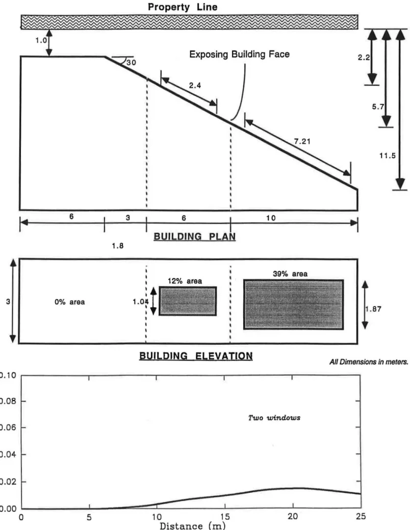
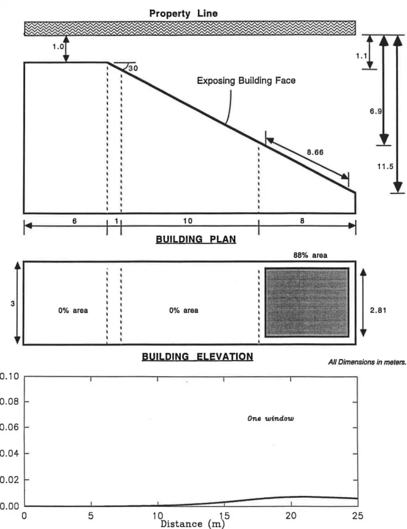
The variation of view factors from the proposed change are compared with two sets of window distributions allowable under the existing code, viz. evenly distributed and concentrated window openings. The effects of extending the proposed code change to account for exposing building faces that are not parallel to the property line have also been investigated (Figures 8 and 9). An exposing building face projecting at a 30° angle to the property line is considered as an example. For such a geometry the applicable equations for direct radiation are similar to those given in Section 2.0 with the exception of Cos <1> 2
. The derivation of the appropriate equations for this scenario, however, is excluded from this paper to maintain brevity.
3.1
Proposed Change for Stepped Exterior Faces
Figure 1 shows the variation of direct radiation view factor - F 12 - along the property line at a distance of 1.5 m above the ground level. The exposing building face geometry and the property line location are also shown in the figure. The building face is composed of three equal areas of 4 m wide by 3 m high at distances of 1.2 m, 4.0 m and 6.0 m from the property line. The maximum allowable window opening areas, according to the proposed change, are also shown as shaded areas on the Building Elevation. Some portions of the stepped exposing building face is perpendicular to the property line. These portions are taken to be non-transparent to direct radiation, in this analysis.
For the example, the view factor reaches a maximum of 5.1% at 2 m from the left end before leveling off around 3%. Simply put, this means the heat flux at the property line could be as high as 5.1% of the building fire itself. It is noteworthy, however, that this maximum value was evaluated by assuming that the fire did not spread on to the exterior surface of the building from the window openings.
3.2
Existing Code with Evenly Distributed Windows.
The solid line in Figure 2 shows the variation of the view factor for a building with its entire exposing building face (12m wide by 3m high) at 1.2 m from the property line. The view factor resulting from the proposed change (Figure 1) is also shown as a broken line. Three window openings of equal area, as allowed by the existing code were considered. The view factors reach a maximum of 5.1% directly opposite the center of
each window. For this example, therefore, the maximum view factor obtained from the proposed change is essentially the same as for the existing code requirement.
Figures 3 and 4 show the view factor variations for a building with the entire exposing building face (12 m by 3 m) at distances of 4 m and 6 m respectively, from the property line. The maximum allowable window areas, as per the existing code, have been employed. The direct view factors reach a maximum of 4.1% and 5.3% respectively, at distances of 4 m and 6 m from the property line. As can be seen, the trend of view factor variation for the two scenarios are essentially the same.
3.3
Existing Code with Concentrated Windows.
Figure 5 shows the variation of direct view factors for a building with its entire face (12m by 3m) at a distance of 1.2 m from the property line. The maximum window area, allowable by the existing code, is placed as a single opening at the center of the building face. Except for the way the opening area is distributed, the amount of window opening area is the same as the configuration in Figure 2. The resulting direct view factor reach a maximum of 9% directly opposite the single window opening. Under the proposed change the direct view factor for a stepped exterior wall reached a maximum of only 5.1 %. It is clear, therefore, that the severity of fire exposure at the property line, under the existing code situation, could be almost twice as much as would be expected from the proposed change.
Figures 6 and 7 show the view factor variations for similar scenarios as for Figures 3 and 4 respectively, except that the windows are concentrated at the centre of the building face. In both situations the view factors reach a maximum of about 6% at the center. The severity of fire exposure (at the property line) for these window opening
configurations is essentially the same for the proposed change and the existing code requirement.
3.4
Proposed Change as Applied to an Angled Wall.
Figures 8 and 9 show view factor variations for an exposed building face placed at a 30° angle to the property line. The same exposing building face is considered for both scenarios. The only difference between them is the (arbitrary) division of the building face. Dotted lines on the Building Elevation and also on the Plan in the two figures indicate the chosen divisions. While the choice of divisions was arbitrary the resulting peak view factors are significantly different. For the two windows scenario (Figure 8) the peak is 0.015 and for the one window scenario (Figure 9) it is half that at 0.007. It may be noted, however, that both these values are well below those obtained for building faces parallel to the property line.
4.0 Conclusions
1. An analysis of Figures 2, 3 and 4 shows that the application of the existing code results in direct view factors at the property line reaching a maximum of 5.1 %. Figure 1 shows that the maximum view factor resulting from the proposed change reaches 5.1 %. This means that, under the configurations analyzed, the proposed change will have little effect on the severity of fire exposure at the property line. For uniformly distributed windows, therefore, the proposed change does not cause the window opening areas to impart a radiation flux at the property line above that which would be expected from the existing code.
2. Results given in Figures 8 and 9 indicate that, the choice of divisions within an exposing building face placed at a 30° angle to the property line, plays a significant role in the property line maximum view factor. In both cases, however, the resulting view factors are much lower than those obtained for a building face which is parallel to the property line. The extension of the proposed change to include angled building faces would not, therefore, impart a radiation flux at the property line higher than that can be expected from the application of the existing code to a building face parallel to its property line.
5.0 Other Issues to be Addressed
1. An analysis of the situation depicted in Figure 5, which is permitted by the current code, with a single large window opening, indicates that, when the maximum allowable window opening space is concentrated at one location, the direct view factor can reach 9% at the property line for a limiting distance of 1.2 m. Though the opening arrangement considered is somewhat extreme, it indicates a vulnerability in the existing code. The most extreme situation will arise if the exposing building face is to contain a single circular shaped window opening. For such a case, it is conceivable that the direct view factor will exceed 10%. This means that the maximum property line heat flux would be 10% of the actual fire heat flux at the exposing building face. Figures 6 and 7 further illustrate the effects of window opening concentration, with resulting maximum view factors of about 6%. In all of these cases, the maximum exceeds that which would be computed using the proposed change for a stepped building face . Obviously, evenly distributed window openings is the preferred method if the maximum radiation heat flux reaching the property line is to be minimized.
2. The existing building code does provide a maximum allowable window opening area as a function of the proximity to the property line and the area of the exposing building face. This analysis indicates, however, that the distribution of the allowable window opening area within the exposing building face is not sufficiently handled in the existing code.
3. It is assumed that the building code specifies the allowable percentage of window openings in an exposing building face to regulate the heat flux received at the property line. From a fire safety point of view, however, the most important parameter would be the maximum anticipated heat flux (or view factor) at the property line. It has been illustrated that different window configurations with the same area of window openings could result in variations in this maximum flux by as much as a factor of two (5.1% versus 9% as shown in Figures 2 and 5 respectively.).
4. The same maximum heat flux at the property line can be regulated by addressing both the window opening area and the distribution of that area on the exposing building face. but keeping the distance to property line fixed. By choosing to distribute the window opening area across the exposing building face, a larger overall opening area can be achieved without exceeding a prescribed maximum. Conversely, a smaller overall opening area would be permitted if the window openings were to be
concentrated in a few locations. This implies that, an optimum may exist between window opening area, window distribution and distance from the property line that would provide the same (or better) fire safety as the existing code. The choice of window opening area and its distribution on an exposing building face from the fire safety viewpoint can be left to the building designers and architects, provided prescribed limits on heat flux at the property line are established.
5. A better solution for regulating the exposing building face openings would, therefore, be to create a performance requirement. The building code need only state the maximum allowable (and perhaps also average) heat flux or view factor at the property line. The building designer or architect would then be at liberty to decide on the disposition of building openings, subject to the ceiling on the anticipated heat flux at the property line. A user friendly computer program, that will accept an exposing building face opening configuration as input, can be developed for this purpose. It
would then be easy to allocate a pass or a fail mark depending upon the maximum and average heat flux received at the property line. As well, the program could specify the minimum distance to the property line for a given window opening configuration.
Acknowledgments
Guidance and direction provided by Igor Oleszkiewicz is gratefully acknowledged. Sincere thanks are due to Ken Richardson, Mohamed Sultan and T.T. Lie for providing valuable conunents.
References
1 Building Code Branch, "The Building Code, containing the Building Code Act and 0. Reg. 419/86",
Ministry of Housing, Toronto, Ontario, 1989.
2 McGuire, J.H., "Fire and the Spatial Separation of Buildings", Fire Tech., v. I, no. 4, pp 278-287, 1965.
3 Williama-Leir, G., " Program for Pocket Calculator to Derive Spatial Separations to Deter Fire Spread", NRC doc. CP 44, 1978
4 Holman, J.P., Heat Transfer, McGraw Hill, New York, NY, 1986.
0 . 10 0.08 0.06 N
-セャッエ@ 0.04 0.02 0.00 1.8 0 2 4Property Line
---....---4Exposing Building Face
)
12 BUILDING PLAN 2.4 BUILDING ELEVATION 6Distance (m)
8/
6I
3 .7All Dimensions in meters.
Proposed Code Chang e
0.10 0.08 0.06 N
-l:l.t 0.04 0.02 0.00 0 2 4 Property LineExposing Building Face
I
1212
BUILDING PLAN
BUILDING ELEVATION
1. 2m from prop. line Three windows
I
/
---6 Distance (m) 8 3All Dimensions in meters
Proposed Code Change
0.10 0.08 0.06 M
....
セ@ 0.04 0.02 0.00 セ@ 0Property Line
Exposing Building Face
12
BUILDING PLAN
BUILDING ELEVATION
Proposed Code Change 4. Om from prop. Three windows line I
__ I
セ@'
I
I ' 2....
-'
...
'
...
---
...
4 6 Distance (m) 8 10 4 3All Dimensions in meters
N セ@ ...
Pronerty Line
6
Exposing Building Face
12
BUILDING PLAN
3
BUILDING ELEVATION All Dimensions in meters
0.10 NMMMMMMMMMセMMMMMMMMセMMMMMMMMセMMMMMMMMセMMMMMMMMセMMMMMMセ@ 0.08 0.06 0.04 0.02
"'
Proposed Code Change 6. Om from prop. line Three windows セ@
,
,
I I I,
/
\ \---
---\---'
.... ---0.00 セMMMMMMMMセMMMMMMMMセMMMMMMMMセMMMMMMMMセMMMMMMMMセMMMMMMMMセ@ 0 2 4 6 Distance (m) 8 10 12Property Line
1.1
Exposing Building Face
イMMMMMMMMMMMMMMMMMMMMMMMセMMMMMMMMMMMMMMMMMMM
12
BUILDING PLAN
3
BUlL PING ELEVATION
All Dimensions in meters
0.10 LMMMMMMMMMNMMMMMMMMMNMMMMMMMMMセMMMMMMMMセMMMMMMMMセMMMMMMMMセ@ 0.08 0.06 N セ@ 0 .04 0.02
Proposed Code Change
I I I
,
,
/
-
..
セ@'
I ' I ' I 'セ@ 1.2m from prop. line Single window
---
---
---セ@ • 0.00 lMMMセセセ]MM⦅j⦅@ _ _ _ _ L _ _ _ _ _ L _ _ M]ZセセMM⦅j@ 0 2 4 6 Distance (m) 8 10 12
N
セM
Property Line
4
Exposing Building Face
12
BUILDING PLAN
3
BUILDING ELEVATION
All Dimensions in meters
0.10 セMMMMMMMMセMMMMMMMMセMMMMMMMMセMMMMMMMMセMMMMMMMMセMMMMMMセ@
0.08
0.06
0.04
0.02
Proposed Code Change
/
-
...
セ@ \
I
I \
4. Om from prop. line / S i n g l e window セMMMMMMZZN⦅@ I I I
'
____
..
-...
...
..
--0 .--0--0 lMMMMMMMセセMMMMMMセMMMMMMMMセMMMMMMMMセMMMMMMMMセMMMMMMMMセ@ 0 2 4 6 Distance (m) 8 10 12Property
Line
6
C::Building Opening Face
12
BUILDING PLAN
3
BUILDING ELEVATION
All Dimensions in meters
0.10 イMMMMMMMMMNMMMMMMMMMNMMMMMMMMMセMMMMMMMMセMMMMMMMMLMMMMMMMセ@ 0.08 0.06 N セM 0.04 0.02 0.00 0
,
-Proposed Code Change
,
,
I I I I/
26.0m from prop. line / S i n g l e window
MMMMMMMMMMMMセMMMM
---4---*___
---6Distance (m)
8 10 12Property Line
Exposing Building Face
11.5
,.
6 3 6I
10セ@
BUILDING PLAN 1.8 I 39% area I I 12% area 3 0% area1.0f
t
BUILDING ELEVATIONAll Dimensions in meters.
0.10 I I I 1 0.08 1-
-Two windows 0.06 1- -セ@ 0.04-
-u:
0.02 r- -0.00 I I I 0 5 10 15 20 25Distance
(m)
Exposing Building Face 6 .9 6 10 8 BUILDING PLAN 88% area 3 0% area 0% area 2.81 BUILDING ELEVATION
All Dimensions in meters.
0.10 I I I I 0.08 f-
-One window 0.06-
-セ@u:
0.04-
-0.02
-
-0.00 J I 0 5 10 15 20 25 Distance(m)
APPENDIX I
PROPOSED CHANGE
TO
I
I
I
I
I
I
I
I
I
I
I
I
I
I
I
I
I
I
PROPOSED REVISION SHEET
Change No: 9.10-04
Date: February, 1992
Page 1 of 2
Reference: 9.10.14.12.
Ontario Building Code, Ontario Reg. 413/90
EXISTING REQUIREMENT
9.10.14.12. Exposing Building Face of Houses
{1) Except as required in Article 9.10.14.3., in buildings containing
only dwelling units in which there is no dwelling unit above another dwelling
unit, the requirements of Article 9.10.14.11. do not apply provided that the
exposing building face has a fire-resistance rating of not less than 45 min
where the limiting distance is less than 1.2 m (3ft 11 in), and when the
limiting distance is less than 0.6 m (23-5/8 in), the exposing building face
is clad with noncombustible material.
(2) Window openings 1n the exposing building face referred to in
Sentence {1) shall not be permitted 1f the limiting
、Qウエ。セ」・@is less than
1.2 m {3 ft 11 in) and shall be limited in conformance with the requirements
for unprotected openings in Article 9.10.14.1. where the limiting distance is
1.2
m(3 ft 11 1n) or greater.
(3) Where the
ウー。エゥセャ@separation between dwelling units on adjoining
properties is registered on the titles of both properties, the spatial
separation may be calculated as if the dwelling units were constructed on the
same property.
PROPOSED CHANGE
Delete Article 9.10.14.12. and substitute:
9.10.14.12. Exposing Building Face of Houses
(1) Except as permitted in Sentence (3), and except as required in
Article 9.10.14.3., in buildings containing only dwelling units in which there
1s no dwelling unit above another dwelling unit, the requirements of Article
9.10.14.11. do not apply provided that the exposing building face has a
fire-resistance rating of not less than 45 min where the limiting distance is less
.than 1.2 m (3ft 11 1n), and when the limiting distance 1s less than 0.6 m
' (23-5/8 in), the exposing building face is clad with noncombustible material.
(2) Except as permitted in Sentence (4) window openings 1n the exposing
building face referred to in Sentence (1) shall not be permitted if the
limiting distance is less than 1.2 m (3 ft 11 in) and shall be
(a) limited in conformance with the percentage of window openings
permitted 1n Table 9.10.14.A. where the limiting distance is 1.2 m
(3 ft 11 in) or greater, or
PROPOSED REVISION SHEET
Change No: 9.10-04
Date: February, 1992
Page 2 of
2Reference: 9.10.14.12.
Ontario Building Code, Ontario Reg. 413/90
(3) For the purposes of determining fire - resistance rating in Sentence
(1) or the percentage of window openings in Sentence (2), the limiting
distance may be calculated
(a) as the least distance to the entire exposing bu11d1ng face, or
(b) as the least distance to each portion of the exposing building face
that is located at a different distance from the property line than
the remainder of the wall.
(4) When the limiting distance has been established in conformance with
Clause (3)(b) the area of window openings in each portion of the exposing
building'face may be calculated by
(a) the percentages permitted by Table 9.10.14.A. of the entire exposing
building face using the limiting distances for each portion of the
wall in the exposing building face, and
(b) multiplying the area of each portion of the wall by the percentage
determined in Clause (4)(a).
(5) Articles 9.10.14.7. and 9.10.14.8. may be used for the purpose of
determining exterior wall construction and percentage of unprotected openings.
(6) Where the spatial separation between dwelling units on adjoining
properties is registered on the titles of both properties, the spatial
separation may be calculated as if the dwelling units were constructed on the
same property.
REASON
New Sentences will permit additional window openings in a portion of a wall
which is set back from the main portion of the exposing building face.
Note: Explanation included on next page.
I
I
I
I
I
I
I
I
I
I
I
I
I
I
I
I
I
I
EXPLANATION OP SENTENCES '9.10.14.•3. (3) AND 9.10.14.3. (4) PARAMETERS
Exposing building face length
=
PJ
+p
2 +P
3 =12 metres.
Exposing building face he1ght
=
3
セ・エイ・ウN@Exposing building face
=
36 m
Limiting distance 1 (L0
1)=
1.2 metres
Limiting distance 2 (L0
2)
=
4.0 metres
Limiting distance 3 (L0
3)=
6.0 metres
Portion 1 (P
1 )of EBF
=
4 metres
=
12 m
2(4m x 3m)
Portion 2 (P
2 )of EBF
=
4 metres
=
12 m
2(4m x Jm)
Portion 3 (P3) of EBF
=
4 metres
=
12 m
2(4m x Jm)
9.10.14.3. (3) (a):
Limiting distance is equal to P
1(1.2m).
9.10.14.3. (3) (b):
Limiting distance may be P
1(1.2m) or P2
(4.0m) or P3 (6.0m)
9.10.14.3. (4) (a) a Ul1 1.21 PIO'ERTl LIIE Ul2 4.0 I i, [.
.
.,__--:-, ---. jl z••
'
LD:J 1.01 , 3••
Amount
of
window
openings
may
be
セ・エ・イュゥョ・、@
from Table 9.10.14.A. usiig the
entire exposing building face (36 m ) and
LD1
(1.2m). This would allow 7\ window
openings or 2.52 m
2(.07X36)
DPOSIIG IUILDIIG FACE
121
9.10.14.3. (4) (b)
Amount of window openings may be determined from Table 9.10.14 .A.
using percentages for LDl' LD2, and L03 based on 36 m
2 exposing
building face. The percentages allowed would be as follows:.
Percent of window openings at L
1for 36 m2
=
7\
Percent of window openings at L2 for 36 m
2 • 36\
Percent of window openings at L3 for 36 m
2
=
80\
1.10.14.3. (4) (b)
Using the percent that P
1,P2 and P3 represent of the total exposing
building face the
セュッオョエ@of window openings would then be calculated
as follows:
Amount of openings permitted in P1
a(36
X.3)
X.07 • 0.84 m
2Amount of openings permitted in P2
=(36 x • 3) x • 36
=
4. 32
ュセ@
Amount of openings permitted in P
3 =(36 x .3) x
.so •
9.60 m
2proセsed@
REVISlON SHEET
Change No: 9.10-05
Date: February, 1992
Page 1 of 2
Reference: Table 9.10.14.A.
Ontario Building Code, Ontario Reg. 413/90
EXISTING REQUIREMENT
Table 9.10.14.A.
Forming Part of Article 9.10.14.1.
·.
Maxi.u. Percentage of Unprotected Openings in Exterior Walls
limiting Distance, m (ft-in)
o」」オq。ョ」セ@Maximum
Class1fi-
Area of Less
cation
ExQos1nq than
of
Bu11d1ng 1.2 1.2 1.5
2.0 4.0
6.0
8.0
10.0 12.0 16.0 20.0 25
Bu1ld1ng
Face,
(J•-
(3•- (4•- (611- (13•- (19
1 -(26
1-{32•- {39•- {54
1-{65•- {82
m
2(ft
2)u•)
1111) 1111) 711) 111)
811)
J•)1011 ) 4•)
611)
711)
o•
Residential 30
HSRSセ@0
7
9
12
39
88
100
-
-
-
-
-「オウQョ・セウ@40 (431
0
7
8
1132
69
100
-
-
-
-
-and
50 {538) 0
7
8
10
28
57
100
-
-
-
-
-gersQnal
100(1080) 0
7
8
9
18
34
56
84
100
-
-
-セ・イカQ」・ウL@Over 100
0
7
7
8
12
19
28
40
55
92
100
-low hazard
(1080)
Qョ、オセエイQ。ャ@Mercantile 30
HSRSセ@0
4
4
6
20
44
80
100
-
-
-
-and medium · 40 (431 . 0
4
4
6
16
34
61
97
100
-
-
-hazard
50 (538) 0
4
4
5
14
29
50
79
100
-
-
-ゥョ、セjウエイQ。ャ@100{1080) 0
4
4
4
9
17
28
42
60
100
-
-Over 100
0
4
4
4
6
10
14
20
27
46
70
1C
(1080)
Column 1
2
3
4
5
6
7
8
9
10
11
12
. 13
1
c·
I
I
I
I
I
I
I
I
I
I
I
I
I
I
I
I
I
PROPOSED REVISION
SHEET
Change No: 9.10-05
Date: February, 1992
Page 2 of 2
Reference: Table 9.10.14.A.
Ontar1o Building Code, Ontario Reg. 413/90
PROPOSED CHANGE
Delete Table 9.10.14.A. and substitute:
Table 9.10.14.A.
Forming Part of Article 9.10.14.1.
Maxi.u. Percentage of Unprotected Openings or
wゥョ、セ@Openings* in Exterior Walls
l1mit1ng Distance, m (ft-1n)
o」」オQR。ョ」セ@
Max1mum
C1ass1fi-
Area of Less
cation
eクQRッセゥョァ@than
of
Buil!;l1ng 1.2 1.2 1.5
2.0 4.0
6.0
8.0
10.0 12.0 16.0
Building
Face,
(3•- (3•- (4•- (611- (13
1 -(19
1-(26
1-(32'- (39'-
(54'-m'
(ft') uu)
11 N) 11 N) JN)1u)
8")
3")
10
11 )4U)
6")
rセセゥ、・ョエゥ。ャ@30 . !323!
0
7
9
12
39
88
100
-
-
-「オセゥョセョ@40
431
0
7
8
1132
69
100
-
-
-Jru!
50
538
0
7
8
10
28
57
100
-
-
-ャャセイウッョャャ@100(1080) 0
78
9
18
34
56
84
100
-セァイカQ」・セL@Over 100
0
7
7
8
12
19
28
40
55
92
low hazard
(1080)
industrial
Mercantile 30 (323) 0
4
4
6
20
44
80
100
-
-tnd medium 40 (431) 0
4
4
6
16
34
61
97
100
-hazard
50 (538) 0
4
4
5
14
29
50
79
100
-industrial 100(1080) 0
4
4
4
9
1728
42
60
100
Over 100
0
4
4
4
6
10
14
20
27
46
(lOBO)
Column 1
2
3
4
5
6
7
8
9
10
1112
Note to Table 9.10.14.A
* See Article 9.10.14.12.
REASON