Publisher’s version / Version de l'éditeur:
Questions? Contact the NRC Publications Archive team at
PublicationsArchive-ArchivesPublications@nrc-cnrc.gc.ca. If you wish to email the authors directly, please see the https://publications-cnrc.canada.ca/fra/droits
L’accès à ce site Web et l’utilisation de son contenu sont assujettis aux conditions présentées dans le site LISEZ CES CONDITIONS ATTENTIVEMENT AVANT D’UTILISER CE SITE WEB.
Short Course on Response of Materials and Structures to Fires [Proceedings], pp. 1-21, 2009-05-20
READ THESE TERMS AND CONDITIONS CAREFULLY BEFORE USING THIS WEBSITE. https://nrc-publications.canada.ca/eng/copyright
NRC Publications Archive Record / Notice des Archives des publications du CNRC : https://nrc-publications.canada.ca/eng/view/object/?id=dd58a59c-70f5-45d8-a05b-332d6d62a83c https://publications-cnrc.canada.ca/fra/voir/objet/?id=dd58a59c-70f5-45d8-a05b-332d6d62a83c
This publication could be one of several versions: author’s original, accepted manuscript or the publisher’s version. / La version de cette publication peut être l’une des suivantes : la version prépublication de l’auteur, la version acceptée du manuscrit ou la version de l’éditeur.
Access and use of this website and the material on it are subject to the Terms and Conditions set forth at
Performance of steel structures exposed to fire Bénichou, N.
Short Course
Response of Materials and Structures to Fires May 20 ‐ 22, 2009
Carleton University, Ottawa, Ontario
Performance of Steel Structures
Exposed to Fire
Noureddine Benichou
National Research Council of Canada
Industrial Research Chair in Fire Safety Engineering
Department of Civil and Environmental Engineering
Behaviour of Steel Structures
in Fire
• When steel structures are under fire exposure:
steel temperatures increase – steel temperatures increase
– strength and stiffness of the steel are reduced
• This leads to deformation and potential failure
• Increase in steel temperatures depends on:
– fire severity
f t l d t fi – area of steel exposed to fire – amount of applied fire protection
Behaviour of Steel Structures in
Fire
• Steel has high thermal conductivity values than
most other materials
most other materials
• Thermal expansion of steel members can cause
damage in other parts of the building
• The main factors affecting the behaviour of steel
structures in fire are as follows:
elevated temperatures in the steel members
Short Course – Response of Materials and Structures to Fires, May 20 – 22, 2009 – elevated temperatures in the steel members
– applied loads on the steel members – mechanical properties of steel members – geometry of the steel members
Protection Systems
• Protected steel members can have excellent fire resistance • Unprotected steel members perform poorly in fires
• Unprotected steel members perform poorly in fires
• A number of alternative passive fire protection systems are available to reduce temperature increase in steel structures exposed to fire – Concrete encasement – Board systems – Spray-on systems – Spray-on systems – Intumescent paint – Concrete filling
Design Methods
• Design for fire resistance requires:
provided fire resistance > design fire severity
• The verification may be in the:
– time domain,
– temperature domain or strength domain
Short Course – Response of Materials and Structures to Fires, May 20 – 22, 2009 – strength domain
Generic Ratings
• The table below is an example taken from NBC
Minimum thickness of solid concrete protection to
steel columns to provide fire resistance (NBC)
Time (hours) 1/2 3/4 1 1.5 2 3 4
Steel Temperatures
Thermal Properties
• To design steel structures for standard or real
fires temperatures of the steel must be known
fires, temperatures of the steel must be known
• For calculating these temperatures, knowledge
of materials thermal properties is necessary
• The density of steel is 7850 kg/m
3and remains
essentially constant with temperature
Short Course – Response of Materials and Structures to Fires, May 20 – 22, 2009
Steel Temperatures
Section Factor
• The section factor is another characteristic to
determine the rate of temp. rise in steel members
• The section factor is a measure of ratio of heated
perimeters to the area of the cross sections as:
F/V (m-1) or H
p / A (m-1)
– F = surface area of unit length of member (mF surface area of unit length of member (m )2)
– V = volume of steel in unit length of member (m3)
– Hp= heated perimeter of cross section (m) – A = cross-sectional area of section (m2)
Section Factor
Short Course – Response of Materials and Structures to Fires, May 20 – 22, 2009
Temperature Calculation
Methods
• Simple calculations can be used to obtain the
t
t
temperatures
• Simple calculations assume a lumped mass of
steel at a uniform temperature over the cross
section of the steel
• The methods are not valid for:
– Members with significant temp. gradients over cross sections, e.g. I-beam with a concrete slab on top – members protected with heavy insulating materials
Best-fit Calculation Method
Unprotected Steel
• The time t (min) for steel to reach a limiting temp.
T
(°C)
h
d t
t
d d fi
T
lim(°C) when exposed to standard fires:
t = 0.54(T
lim- 50)/(F/V)
0.6• F/V is the section factor (m
-1)
• This expression is valid for:
10 min≤ t ≤ 80 min
Short Course – Response of Materials and Structures to Fires, May 20 – 22, 2009 – 10 min ≤ t ≤ 80 min
– 10 ≤ F/V ≤ 300 m-1
– 400°C ≤ Tlim≤ 600°C
Best-fit Calculation Method
Protected Steel
• The time t (min) for a steel member protected
ith
i
l ti
t
h T
(°C)
h
with an insulation to reach T
lim(°C) when
exposed to standard fires:
t = 40 (T
lim- 140) [(d
i/ k
i)/(F/V)]
0.77• k
iis the thermal conductivity of insulation (W/m-K)
• d
iiis the thickness of the insulation (m)
( )
• This equation is valid for:
– 30 ≤ t ≤ 240 min – 0.1 ≤ di/ki≤ 0.3 m2K/W
Best-fit Calculation Method
Protected Steel
• For insulation containing moisture, a time delay
t
v(min) can be added to the time t using:
t
v= m ρ
id
i2/ (5k
i)
•
ρ
iis the insulation density (kg/m
3)
• m is the insulation moisture content (%)
Short Course – Response of Materials and Structures to Fires, May 20 – 22, 2009
Step-by-step Calculation Method
Unprotected Steel
• The calculation method for unprotected steel is:
4 4
ΔT
s= (F/V)(1/(ρ
sc
s)) [h
c(T
f-T
s) + σε(T
f4-T
s4)] Δt
• ΔTsis the change in steel temperature (°C or K) • ρsis the density of steel (kg/m3)
• csis the specific heat of steel (J/kg K)
• hcis the convective heat transfer coefficient (W/m2K)
• σ is the Stefan-Boltzmann constantσ is the Stefan Boltzmann constant • ε is the resultant emissivity (0.50)
• Tfis the temperature in the fire environment (K)
• Tsis the temperature of the steel (K)
Step-by-step Calculation Method
Protected Steel
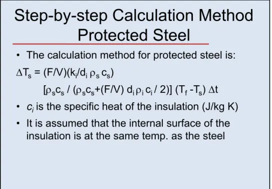
• The calculation method for protected steel is:
ΔT
s= (F/V)(k
i/d
iρ
sc
s)
[ρ
sc
s/ (ρ
sc
s+(F/V) d
iρ
ic
i/ 2)] (T
f-T
s) Δt
•
c
iis the specific heat of the insulation (J/kg K)
• It is assumed that the internal surface of the
insulation is at the same temp as the steel
Short Course – Response of Materials and Structures to Fires, May 20 – 22, 2009
insulation is at the same temp. as the steel
Step-by-step Calculation Method
Protected Steel
Table of thermal properties of insulation materials
Material Density ρi (kg/m3) Thermal conductivity ki (W/m-K) Specific heat ci (J/kg K) Equilibrium moisture content % Sprays:
Sprayed mineral fibre
300 0.12 1200 1
Perlite or vermiculite plaster 350 0.12 1200 15 High-density perlite or vermiculite plaster 550 0.12 1200 15 Boards: 600 0.15 1200 3 Fibre-silicate or fibre-calcium silicate Gypsum plaster 800 0.20 1700 20
Compressed fibre boards: Mineral wool, fibre silicate
Step-by-step Calculation Method
Spreadsheet calculation for temperatures of steel
p
p
Time Steel temperature Ts Fire temperature Tf Difference in temperature Change in steel temperature ΔTs t1 = Δt Initial steel temperature Tso Fire temperature halfway through time step (at Δt/2)
Tf - Tso Calculate from equation of ΔTs with values of Tf and Tso from this row
t2 = t1 + Δt Ts from previous time step +ΔTsfrom
Fire temperature half way through time step
Tf - Ts Calculate from Equation ofΔTs
Short Course – Response of Materials and Structures to Fires, May 20 – 22, 2009
step ΔTs from previous row y g p (at t1 + Δt/2) Equation of ΔTs with values of Tf and Ts from this row
WORKED EXAMPLE
• Use the step-by-step method to calculate the steel
t
t
f
t
t d
d
t
t d
temperature of an unprotected and protected
beam exposed to the ISO 834 standard fire.
• F/V=200 m
-1, h
c
=25 W/m
2K,
ε=0.6, ρ=7850 kg/m
3,
c
s=600 J/kg-K, d
i=50 mm, k
i=0.2 W/m-K,
100 J/k K
300 k /
3Δt 0 5 i
WORKED EXAMPLE
• The first two minutes of the solution are shown
Time (minutes) Time at half step Steel temperature ISO fire temperature at Difference in temperature Change in steel (minutes) step temperature
Ts temperature at half step Tf temperature steel temperature 0.0 0.25 20.0 184.6 164.6 6.8 0.5 0.75 26.8 311.6 284.7 13.8 1.0 1.25 40.6 379.3 338.7 18.2 1.5 1.75 58.8 425.8 366.9 21.5 2.0 2.25 80.3 461.2 380.9 24.0 2.5 3.0 Time ( i t ) Time at half t Steel t t ISO fire t t t Difference in t t Change in t l
Short Course – Response of Materials and Structures to Fires, May 20 – 22, 2009
(minutes) step temperature Ts temperature at half step Tf temperature steel temperature 0.0 0.25 20.0 184.6 164.6 0.62 0.5 0.75 20.6 311.6 290.9 1.10 1.0 1.25 21.7 379.3 357.6 1.35 1.5 1.75 23.1 425.8 402.7 1.52 2.0 2.25 24.6 461.2 436.6 1.65 2.5 3.0
Typical Steel Temperatures
Typical steel temp. for unprotected/protected steel
b
d t
t
d d fi
Structural Design of Steel
Members
• The structural design steel structures exposed to
fire requires knowledge of:
fire requires knowledge of:
– temperatures in the steel and
– mechanical properties at elevated temperatures
• Structural design requires prevention of:
– collapse (strength limit) – most important in design
– excessive deformations (serviceability limit)
Short Course – Response of Materials and Structures to Fires, May 20 – 22, 2009 excessive deformations (serviceability limit)
• Design methods are grouped in two categories :
– simplified methods for individual/single elements – general methods for buildings (frames or structures)
Mechanical properties of steel
Stress-related Strain
Hot rolled steel stress-strain curves
Yield strength and proof strength
Mechanical properties of steel
Design values
Short Course – Response of Materials and Structures to Fires, May 20 – 22, 2009 Yield strength and modulus of elasticity of steel
Design Methods
• Verification in the strength domain requires:
U
*fire
≤ Φ R
fire• U
*fire
is design force resulting from applied loads
at the time of the fire
• R
fireis load-bearing capacity in fire situation
(equations in codes/standards can be adapted)
•
Φ is strength reduction factor (usually equal to 1
Design of Individual Members
Tension members
• The design equation:
N
*≤ N
N
*fire
≤ N
fN
f= A k
y,Tf
y (uniform temp.)N
f= ∑
i=1,nA
ik
y,Tif
y (temp. gradient)• A and Ai– area/elemental area of cross section (mm2)
Short Course – Response of Materials and Structures to Fires, May 20 – 22, 2009
i ( )
• ky,Tand ky,Ti- reduction factor for yield strength of steel • fy- yield strength of the steel at ambient (MPa)
• T and Ti– temperatures
Design of Individual Members
Simply supported beams
• The design equation is:
M
*≤ M
M
fire≤ M
fM
f= S k
y,Tf
y (uniform temp. - plastic)M
f= Z k
y,Tf
y (uniform temp. - elastic)M
f= ∑
i=1,nA
iz
ik
y,Tif
y(temp. gradient)∑
i=1,nA
ik
y,Tif
y= 0
(neutral axis location at time t)• S and Z – plastic/elastic section modulus (mm3)
• zi- distance from the plastic neutral axis to the centroid of the elemental area
• Susceptibility of beams to local buckling should be considered
Design of Individual Members
-Simply supported beams
Short Course – Response of Materials and Structures to Fires, May 20 – 22, 2009 • The equation for elastic design should be used for Class 3
sections (elastic moment without local buckling)
• For light cold-rolled sections susceptible to local buckling (Class 4), equations are not applicable
Worked Example
A simply supported steel beam with a span of
8 m,
known load, yield strength, and section properties.
, y
g ,
p p
Calculate the flexural strength after 15 minutes
exposure to the standard fire. The beam has no
applied fire protection and is exposed on 3 sides.
Given
• Dead load Gk= 8.0 kN/m (including self weight)
• Live load Q = 15 0 kN/m • Live load Qk= 15.0 kN/m
• Beam size 410 mm deep and 54 kg/m (section class 1) • Plastic section modulus S = 1060 x 103mm3
• Section factor F/V = 190 m-1
Worked Example
Cold Calculations
Strength reduction factorΦ 0 9 • Strength reduction factor Φ = 0.9
• Design load (cold) wc= 1.2Gk+ 1.6Qk= 33.6 kN/m • Bending moment M*
cold= wcL2/8 = 269 kN-m
• Bending strength Mn= Sfy= 318 kN-m (assume adequate
lateral restraint)
• Design flexural strength ΦMn= 286 kN-m
Short Course – Response of Materials and Structures to Fires, May 20 – 22, 2009
g g n • Design is OK (M* cold< ΦMn)
Worked Example
Fire Calculations
S h d i f 1 0 (h d i h• Strength reduction factor Φ = 1.0 (hence not used in the calculations)
• Design load (fire) wf = Gk+0.4Qk= 14.0 kN/m • Bending moment M*
fire= wfL2/8 = 112 kN-m
• Temperature after time t:
T = 1 85t (F/V)0.6+50 (best fit equation)
T 1.85t (F/V) +50 (best fit equation) • Temperature after 15 minutes:
T = 1.85 x 15 x 1900.6+ 50 = 696°C
Worked Example
• Flexural capacity:
M = S k f (assume adequate lateral restraint) Mf= S ky,Tfy(assume adequate lateral restraint) Mf= 1060 x 103x 0.30 x 300/106= 95 kN-m
• Design fails (M*
fire> Mf)
(Note: For more accurate temperature calculations, the step-by-step method could be used. The flexural
calculation method would be the same.)
Short Course – Response of Materials and Structures to Fires, May 20 – 22, 2009
Design of Individual Members
Columns
• The design equation is:
N
*fire
≤ N
fN
fire≤ N
fN
f= (χ
fi/1.2) A k
y,Tmf
y (Eurocode approximation) • The whole cross section is assumed at the maximumtemperature Tm
• χfiis the ambient buckling factor, calculated using the effective buckling length for fire design cases
effective buckling length for fire design cases • 1.2 is an empirical correction factor
• A is the area of the cross section, ky,Tmis the reduction
factor for the yield strength of steel at Tm, and fyis the yield strength of the steel at ambient
Design of Steel Buildings
Exposed to Fire
• Steel buildings design cannot be cost-effective
by the simple methods described previously
• It is necessary to use computer programs for
analysis of the fire-exposed structure
• Programs will impose deformations on the
structure and calculate the total strain in a
Short Course – Response of Materials and Structures to Fires, May 20 – 22, 2009
member resulting from the deformations
• Calculated fire resistance of a structural steel
member is enhanced when part of a frame
Layout of the car park structure
O
ll di
i
Fire in a Car Park Structure
-Example
- Overall dimensions
- Type of steel sections used
Composite slab Thickness = 0.12 m HEA500 3.33 m 3.2 m 10.0 m 15.0 m 4.2 m IPE550 HEB240 IPE500 IPE550 3.33 m HEB240
Fire in a Car Park Structure
-Example
Short Course – Response of Materials and Structures to Fires, May 20 – 22, 2009 Ignition of one of the cars Fully developed fire
Fire in a Car Park Structure
-Example
Types of elements
BEAM : columns
Types of elements used for modelling the structure
SHELL : concrete slab
BEAM : steel sections, profiled steel sheets and concrete ribs PIPE : connection between
steel sections and composite slab
Fire in a Car Park Structure
-Example
Deformation of Deformation of the floor after 32 minutes of fire
Short Course – Response of Materials and Structures to Fires, May 20 – 22, 2009
Fire in a Car Park Structure
-Example
Stress distribution on the exposed side of the concrete slab after 32 minutes of fire
Fire in a Car Park Structure
-Example
Short Course – Response of Materials and Structures to Fires, May 20 – 22, 2009 Strains of steel mesh within the concrete slab after 32 minutes Maximum temperatures
within structural elements
References
• ZHAO B. & KRUPPA J. (March 2002). Numerical modelling of structural behaviour of open car parks under natural fires.SIF 02 – Structures in Fire – 2ndInternational Workshop – Christchurch (NZ)