HAL Id: inria-00638565
https://hal.inria.fr/inria-00638565
Submitted on 5 Nov 2011
HAL is a multi-disciplinary open access
archive for the deposit and dissemination of
sci-entific research documents, whether they are
pub-lished or not. The documents may come from
teaching and research institutions in France or
abroad, or from public or private research centers.
L’archive ouverte pluridisciplinaire HAL, est
destinée au dépôt et à la diffusion de documents
scientifiques de niveau recherche, publiés ou non,
émanant des établissements d’enseignement et de
recherche français ou étrangers, des laboratoires
publics ou privés.
Some Desired Features for the DEVS Architecture
Description Language
Olivier Dalle, Judicaël Ribault
To cite this version:
Olivier Dalle, Judicaël Ribault. Some Desired Features for the DEVS Architecture Description
Lan-guage. Symposium On Theory of Modeling and Simulation – DEVS Integrative M&S Symposium
(TMS/DEVS 2011), Apr 2011, Boston, MA, United States. pp.258-263. �inria-00638565�
Some Desired Features for the DEVS Architecture Description Language
Olivier Dalle - Judica¨el RibaultINRIA - CRISAM
University of Nice Sophia Antipolis I3S-UMR CNRS 6070
BP93 - 06903 Sophia Antipolis, France [email protected]
Keywords: ADL, Architecture, Component, Reuse,
Scala-bility
Abstract
ADL are particularly well suited for component-based model frameworks that support hierarchical composition, such as DEVS with coupled models. In this paper we present some features found in the ADL of another hierarchical component model, namely the Fractal Component Model (FCM). To our best knowledge, these features are not yet available in most of the current DEVS implementations. Using a few examples coming from our experience, we demonstrate the usefulness of these features for Modeling & Simulation and their poten-tial relevance for inclusion in a future DEVS implementation standard.
1.
INTRODUCTION
Architecture Description Languages (ADL) are special-ized languages for describing the architecture of complex multi-parts software. ADL are particularly well suited for component-based model frameworks that support hierarchi-cal composition, such as DEVS with coupled models.
Concepts commonly associated with the field of software architectures are [1]:
• components that represent the basic entities of an appli-cation,
• connectors that identify the types of interactions be-tween components of the architecture,
• configurations that describe an architecture in terms of components and connectors,
• composites that reify a configuration as a component. In this paper we present a few selected features found in the ADL of other hierarchical component models, and in partic-ular in the Fractal Component Model[2] (FCM). The aim of this paper is to demonstrate the usefulness of these features and advocate for their inclusion in a future DEVS software specification standard. It is worth emphasizing that, with re-spect to our previous publications, this paper does not present new ideas but rather gives a synthetic view on the ideas that
were introduced and further developed in other papers[3], [4], [5], [6], [7], [8]. This paper is intended to help discussions about the standardization of DEVS.
The selected features described in this paper have been chosen because they are actually offered by the FCM. The FCM has been implemented in various languages including Java, and C/C++. The features described in this paper are ac-tually mostly related the FractalADL Java Library[9], which is a supporting Library for the various Java implementations of the FCM. Indeed, our experience and motivation for rec-ommending these features comes from our experience in us-ing them within the Open Simulation Architecture project (OSA)[10], which is based on such a Java-based implemen-tations of the FCM.
The remainder of this paper is organized as follows: in Sec-tion 2., we describe the features in a general way and discuss their relevance with the DEVS formalism; Then, in Section 3., with give a few examples to illustrate some practical use of these features; finally, we conclude in Section 4..
2.
DESCRIPTION OF THE DESIRED
FEA-TURES
In this section, we introduce the features that we would like to recommend for the DEVS standardization. First, before we introduce these three features, we start with an overall intro-duction to the FractalADL library, in section 2.1.. Then, in section 2.3., we discuss the feature of extensibility and over-loading of architecture definitions, which helps to enforce reuse of software and provides an excellent basis for compar-ative studies. Then, in section 2.4., we discuss the feature of using templates and iterative constructions for building large-scale simulation software architectures. Last, in section 2.5., we advocate the use of the shared components, an original FCM construct that allows a better modeling of some situ-ations and proves to be helpful in tuning the complexity of models.
2.1.
Introduction to Fractal and FractalADL
Compared to standard (Java) object instances, components have the ability to support (or obey to) non-functional con-cerns, such as life-cycle, naming, access control or persis-tence to name a few. More precisely, “non-functional” means
that it is a concern that is not related to the business logic of a given component, but applies equally to all components. Let’s look closer at an example with the life-cycle concern: the life-cycle concern is about starting and stopping a compo-nent without compromising the whole application; it is meant for high-availability applications, to allow any component to be safely replaced with an upgraded version without shutting down the whole application. This concern applies equally to all the components of the application regardless of their spe-cific business: it is a non-functional concern.
In Fractal, these non-functional concerns are implemented by means of dedicated controllers, placed beside the func-tional code (or merged with it, depending on the Fractal im-plementation). The list of controllers associated to a given component is merged into an entity called a membrane in the Fractal jargon. Compared to other component models, an in-teresting feature of Fractal is that it allows to build new cus-tom membranes, by adding, removing or replacing any such controller to or from an existing membrane.
Despite most of the Fractal implementations come with a minimal set of default controllers, none are explicitly re-quired by the Fractal specification. This lack of minimal requirement makes the component model extremely versa-tile, but it incurs a slightly heavier programming cost, be-cause the exact list of available controllers must be retrieved by introspection. For example, let’s consider the so-called naming-controller, which is in charge of assigning a name (any string value) to a component. Because this very basic feature is optional, the corresponding controller is not required to be present. Therefore, a careful programming re-quires that introspection is used to retrieve that controller prior to using it, because there is a risk that it might not be available. This programming constraint is a deliberate choice of the FCM designers. On one hand, if that naming feature was required to be present in all components, then the pro-gramming would be easier because the corresponding con-troller could be accessed without caution. On the other hand, forcing any feature that could be useless to be associated to all component might result in very big components each pos-sibly having a significant amount of useless code (and bugs). The Fractal Architecture Description Language (Fractal-ADL) is a contributed software Library, written in Java, which is part of the ObjectWeb Consortium’s Fractal project. FractalADL provides a Factory component that reads archi-tectures descriptions from files and build the corresponding hierarchical component-based software architecture in mem-ory. These architecture descriptions are provided as XML definitions, according to a Document Type Definition (DTD). The FractalADL Library is built using a collection of Frac-tal components. Interestingly the component assembly that forms the FractalADL factory component is built recursively: it reads its own architecture description (ie., the architecture
of the hierarchical components used to implement the Frac-talADL factory) using a hard-coded bootstrap component ar-chitecture. Thanks to this flexible, reflexive architecture, the FractalADL components can be extended at will, which in turn allows to extend the ADL itself, and therefore the lan-guage definitions it is able to recognize. This flexibility might seem excessive, but it is consistent with the Fractal philos-ophy described earlier, in which the non-functional services provided by the membrane of a component can be customized and extended at will. This ability has been used to extend the original ADL in various directions, such as including sup-port for the distributed execution of components for example. In the OSA project[10], we used this extension capability to allow the scheduling of exogenous events directly within a (model) architecture definition, or to specify the points in the modeling code where to collect data samples for the instru-mentation framework.
Although almost all the content of the Factory could be re-engineered, and therefore almost all its functional specifi-cations could be changed, a typical FractalADL Factory sup-ports the following constructs :
• definition of a component, which is a container for more definitions, specifying its name and source (either binary code or another ADL definition file),
• specification of component interfaces (services offered and used),
• list of components bindings (how services offered by some components are connected to services used by oth-ers)
• component location (on which host to deploy the com-ponent instance for execution)
• component content (list of sub-components in case of a hierarchical component)
• component special features (eg. the template feature de-scribed later on, or the capability of scheduling of simu-lation events used in OSA )
The Listing 1 illustrates the previous basic constructs through a simple client-server example: at the top level, the application is composed of two components, a client, named “client” and a server named “Server”. Since the semantics of each XML tag-word is self-explanatory, it is not to be further explained. In the remaining of this paper, the two first lines declaring XML encoding and DOCTYPE are skipped for the sake of brevity.
1 <?xml version= ” 1 . 0 ” encoding= ” ISO−8859−1” ?> 2 <!DOCTYPE d e f i n i t i o n = ” s k i p p e d . . . ” > 3 4 <d e f i n i t i o n name= ” C l i e n t S e r v e u r A p p ”> 5 <component name= ” C l i e n t ”> 6 <i n t e r f a c e name= ” c l i ” 7 role= ” c l i e n t ” 8 signature= ” C l i e n t S v c ”/> 9 <c o n t e n t c l a s s= ” C l i e n t I m p l ”/> 10 </component> 11 12 <component name= ” S e r v e r ”> 13 <i n t e r f a c e name= ” s r v ” 14 role= ” s e r v e r ” 15 signature= ” S e r v e r S v c ”/> 16 <c o n t e n t c l a s s= ” S e r v e r I m p l ”/> 17 </component> 18 19 <b i n d i n g client= ” C l i e n t . c l i ” 20 server= ” S e r v e r . s r v ”/> 21 </ d e f i n i t i o n >
Listing 1. A sample FractalADL declaration that defines an application made of client and a server.
2.2.
Similarities and potential connection with
DEVS
DEVS and Fractal are both hierarchical component mod-els. While DEVS describes the interactions between com-ponents by means of input/outputs, Fractal interconnects its components using client-server interface bindings. In other words, in Fractal, components interact using method calls, also called messages in OOP jargon. In the most simple cases, one can easily find a way of translating one form into the other (eg. DEVS to Fractal) and conversely: asynchronous method calls can be serialized and transformed into DEVS in-put/outputs while DEVS point-to-point inin-put/outputs can be exchanged between Fractal components using client-server method calls. More complex interactions, such as point-to-multi-points DEVS couplings, can be solved either by adding extra fractal multiplexing components to route a single event to its multiple destinations, or by adding a multi-point con-troller directly in the membrane of the fractal components supporting complex bindings between Fractal components. However, some translations are a bit more difficult between both models, such as translating in DEVS a Fractal syn-chronous method call (a method call that returns a result value to the caller). In that case, the method call has to be split in two events, one sent to the callee with the method call and pa-rameters, and another one on the way back to the caller with the method result.
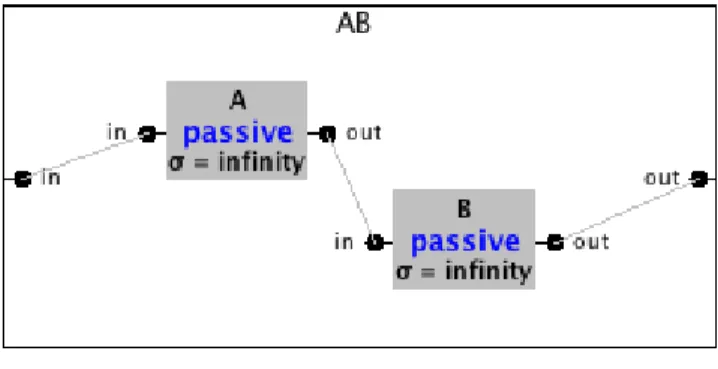
When looking at implementations, these similarities are quite obvious. Let’s consider for example the case of DE-VSJava and Julia, which are Java implementations of respec-tively DEVS and FCM and consider the sample architecture presented in Figure 1.
Using the formal DEVS representation, the first level of this architecture can be described as follows (cf. [11]) :
Figure 1. A simple “pipeline” coupled architecture in DE-VSJava 1 p u b l i c Pipeline ( ) { 2 s u p e r( ”AB” ) ; 3 4 / / D e f i n e AB ’ s e x t e r n a l p o r t s 5 addInport( ” i n ” ) ; 6 addOutport( ” o u t ” ) ; 7 8 / / I n s t a n t i a t e sub−c o m p o n e n t s 9 ViewableAtomic a = new proc ( ”A” , 1 0 ) ; 10 ViewableAtomic b = new proc ( ”B” , 1 0 ) ; 11 12 / / i n c l u d e AB ’ s sub−c o m p o n e n t s 13 add( a ) ; 14 add( b ) ; 15 16 initialize( ) ; 17 18 / / E x t e r n a l I n p u t C o u p l i n g ( s ) 19 addCoupling( t h i s , ” i n ” , a , ” i n ” ) ; 20 / / I n t e r n a l C o u p l i n g ( s ) 21 addCoupling( a , ” o u t ” , b , ” i n ” ) ; 22 / / E x t e r n a l O u t p u t C o u p l i n g ( s ) 23 addCoupling( b , ” o u t ” , t h i s , ” o u t ” ) ; 24}
Listing 2. Java code used in DEVSJava to build the pipeline coupled architecture presented in Figure 1.
AB = < X,Y, D, {Md|d ∈ D}, EIC, EOC, IC >
= < {in, x ∈ Xin}, {out, y ∈ Yout},
{A, B}, {MA,MB},
{((AB, in), (A, in))}, {((B, out), (AB, out))}, {((A, out), (B, in))} >
where MA and MB are two basic DEVS components
(atomic or coupled) each having the same input and output ports as AB.
In DEVSJava, the code of the following Listing 2 imple-ments this “pipeline” coupled architecture: the external ports are declared by lines 5-6, the instances of A and B are cre-ated by lines 9-10 and inserted in AB by lines 13-14; then the couplings are created by lines 19-23.
In Fractal/Julia, as shown in the Listing 3 hereafter, the code is slightly more lengthy because of introspection (see
1 GenericFactory cf = Fractal . getGenericFactory ( boot ) ; 2 / / I n s t r u c t i o n s s k i p p e d . . .
3 / / c r e a t e t y p e s abType , a T y p e and b T y p e . . . 4
5 / / c r e a t e i n s t a n c e o f AB c o m p o n e n t
6 Component ab = cf . newFcInstance ( abType , ” c o m p o s i t e ” , n u l l) ;
7 / / c r e a t e i n s t a n c e o f t y p e A c o m p o n e n t
8 Component a = cf . newFcInstance ( aType , ” p r i m i t i v e ” , ” a I m p l ” ) ;
9 / / c r e a t e i n s t a n c e o f t y p e B c o m p o n e n t
10 Component b = cf . newFcInstance ( bType , ” p r i m i t i v e ” , ” b I m p l ” ) ;
11
12 / / add sub−c o m p o n e n t s a & b i n ab
13 Fractal. getContentController ( ab ) . addFcSubComponent ( a ) ; 14 Fractal. getContentController ( ab ) . addFcSubComponent ( b ) ; 15
16 / / b i n d c o m p o n e n t i n t e r f a c e s
17 Fractal. getBindingController ( ab ) . bindFc ( ” i n ” , a . getFcInterface( ” i n ” ) ) ;
18 Fractal. getBindingController ( a ) . bindFc ( ” o u t ” , b . getFcInterface( ” i n ” ) ) ;
19 Fractal. getBindingController ( b ) . bindFc ( ” o u t ” , ab . getFcInterface( ” o u t ” ) ) ;
Listing 3. Java code used in Fractal/Julia to build the pipeline coupled architecture presented in figure 1.
earlier discussion in section 2.1.), but no more difficult to un-derstand: line 1, the Java main method must first retrieve the component factory from the static Fractal object; then af-ter a few instructions required to create the component types (this step is required for some obscure reason that do not need to be discussed here), the three components are instantiated by lines 6-10, and A and B are inserted in AB by lines 13-14; then the couplings, called “bindings” in FCM are established by lines 17-19.
2.3.
Extension and overloading of definitions
A FractalADL definition can be divided into several sub-definitions that can be read from separate files. Moreover, the language supports a mechanism to ease the extension and re-definition through inheritance. Hence this mechanism allows to reuse previous architecture definitions in order to build new definitions that extend or replace the existing ones.
Indeed, when a definitionB extends a definition A, B pos-sesses all the elements defined in definitionA, like an internal copying mechanism. Moreover, if definitionB defines an el-ement that has the same name in definitionA, B’s definition overridesA’s one. The extension mechanism allows to create a new definition by composition of existing definitions.
For example, let us consider the example given in List-ing 4. This FractalADL definition, named models.hello-world.client, declares a Fractal component named Clientwhose Java content is provided by the class mo-dels.helloworld.ClientModel. This Fractal com-ponent also has a (Fractal) client-type interface named ser-verand typed by the Java interface signature ServerItf.
1 <d e f i n i t i o n name= ” m o d e l s . h e l l o w o r l d . c l i e n t ”> 2 <component name= ” C l i e n t ” > 3 <c o n t e n t c l a s s= ” m o d e l s . h e l l o w o r l d . C l i e n t M o d e l ”/> 4 <i n t e r f a c e name= ” s e r v e r ” 5 role= ” c l i e n t ” 6 signature= ” S e r v e r I t f ”/> 7 </component> 8 </ d e f i n i t i o n >
Listing 4. An example of a simple FractalADL component definition. 1 <d e f i n i t i o n name= ” m o d e l s . h e l l o w o r l d . c l i e n t a l t ” 2 e x t e n d s ” m o d e l s . h e l l o w o r l d . c l i e n t ”> 3 4 <component name= ” C l i e n t ” > 5 <i n t e r f a c e name= ” s e r v e r ” 6 role= ” c l i e n t ” 7 signature= ” A t l e r n a t e I t f ”/> 8 </component> 9 </ d e f i n i t i o n >
Listing 5. FractalADL definition overloading the previous definition of Listing 4 with an alternate interface signature.
In the simplest form, overloading allows to replace or ex-tend some parts of a Fractal definition. For example, in List-ing 5, a new definition is given that overloads the previous definition of Listing 4, such that the interface signature is now given by the AlternateItf Java interface instead of ServerItf. Notice that in this new definition, the con-tent of the component is not specified, which triggers the in-heritance mechanism: by default, the new definition inherits from all the definitions given in the original definition, and the change only applies to the pre-existing interface named server. This change only occurs because in both defini-tions, the interface is given the same server name. In case the name would differ, then this new definition would add a second client interface to the component instead of replacing its existing one.
The FractalADL overloading and inheritance mechanisms allow more complex constructions based on multiple inher-itance. For example, in addition to the previous definitions of Listing 4, we could add a second definition such as the one given in Listing 6. Notice both definitions define the same component named Client but with totally different contents. Without entering the details, the second definitions gives details about the simulation scenario in which the com-ponent will be used, such as the specification of an exogenous event to be injected in that component at time tval (tval is a pseudo-variable provided by a scripting mechanism of FractalADL that is not further described in this discussion). Notice this second definition is not overloading the first one (no extends keyword); it is fully independent of the first one. Hence, a third definition is required to merge these two almost conflicting definitions. Such a merging definition is
1 <d e f i n i t i o n name= ” s c e n a r i o s . h e l l o w o r l d . c l i e n t ” a r g u m e n t s = ” t v a l ”>
2
3 <component name= ” C l i e n t ”>
4 <i n t e r f a c e name= ” h e l l o ” role= ” s e r v e r ” signature= ” H e l l o I t f ”/>
5 <exoevents signature= ” h e l l o ”> 6 <exoevent name= ” s t a r t ” type= ”
S t a r t O f C a l l ” time= ” ${ t v a l }” 7 method= ” g e n e r a t e H e l l o ” />
8 </exoevents>
9 </component> 10 </ d e f i n i t i o n >
Listing 6. Another FractalADL definition for the “client” component of Listing 4
1 <d e f i n i t i o n name= ” e x p e r i e n c e . h e l l o w o r l d . c l i e n t ”
2 e x t e n d s= ” m o d e l s . h e l l o w o r l d . c l i e n t , s c e n a r i o s . h e l l o w o r l d . c l i e n t ( 1 2 ) ”/>
Listing 7. A FractalADL definition that merges multiples definitions into a single compound one.
given by Listing 7 in which the
experience.hello-world.client component results from the merging of
both the previous models.helloworld.client and
scenarios.helloworld.client(12)(the value 12
being passed to the tval argument of the latter definition).
2.4.
Templates and iterative constructions
In a given architecture, the same component often needs to be instantiated several times. For example, in a Peer-to-peer network simulation, the model of the Peer-to-peer node might need to be instantiated thousands of times. When the com-ponent to be multi-instantiated is primitive/atomic, it is suf-ficient to repeat the same declaration. Indeed, the ADL does not always offer a loop mechanism (this is the case in Fracta-lADL), which requires to describe the complete architecture as shown in listing 8: Line 1 names the architecture; Lines 2-7 describe the 3 components Node1, Node2 and Node3 whose definition are given in another file named Node.Fractal. The definition described in this file represents a component supposed to have a client interface named “link”. Lines 8-9 describe the Server component whose definition located in the file Server.Fractal that represents a primitive com-ponent with a server interface named “link”. Finally lines 18-20 describe the connection between the 3 components Node1, Node2 and node3 with component Server.
Reusing this architecture is not easy if we want to vary the number of Nodes in the application. The FCM allows through the Factory and Template constructs to describe only one tem-plate component Node and bind it to a Factory component that will take care of its replication. Notice that the templated component (in our case, the peer Node component) can be of arbitrary complexity: in case of a hierarchical component, the whole hierarchy is replicated. Hence the only difference
1 <d e f i n i t i o n name= ” f r . i n r i a . o s a . N o d e S e r v e r E x a m p l e 1 ”> 2 <component name= ” Node1 ”
3 d e f i n i t i o n= ” f r . i n r i a . o s a . Node ”/> 4 <component name= ” Node2 ”
5 d e f i n i t i o n= ” f r . i n r i a . o s a . Node ”/> 6 <component name= ” Node3 ”
7 d e f i n i t i o n= ” f r . i n r i a . o s a . Node ”/> 8 <component name= ” S e r v e r ” 9 d e f i n i t i o n= ” f r . i n r i a . o s a . S e r v e r ”/> 10 <b i n d i n g client= ” Node1 . l i n k ” 11 server= ” S e r v e r . l i n k ” /> 12 <b i n d i n g client= ” Node2 . l i n k ” 13 server= ” S e r v e r . l i n k ” /> 14 <b i n d i n g client= ” Node3 . l i n k ” 15 server= ” S e r v e r . l i n k ” /> 16 </ d e f i n i t i o n >
Listing 8. Model architecture without loop
between a normal component and a template component, is the fact that the template component offers an additional non-fonctional replication service.
Since the template feature is a non-functionnal concern, it can be added by means of a controller in the membrane of any component. However, the template feature does not al-low a component to be used as easily as a regular one. In particular, since the component can be replicated an arbitrary number of times, a mechanism is required to establish the ex-ternal bindings between the new instances of the (template) component and other components. This is what the Factory component is used for: the Factory component is in charge of supervising the process and establishing the binding (ie. cou-plings) dynamically while new instances of the template are replicated.
We first presented this Template/Factory in [8]; it is slightly different from the original mechanism proposed in the Fractal reference implementations, which do not support overloading and reuse of template as well as our proposed solution.
Let us consider an example: Listing 9 shows the Fractal description on which we want to apply the Template/Factory mechanism. Line 1 names the architecture. Lines 2-3 describe the Node component whose description is defined in the file Node.Fractal. The definition described in this file repre-sents a primitive component having a client interface named “link”. Lines 4-5 describe the Server component whose def-inition located in the file Server.Fractal, which repre-sents a primitive component with a server interface named “link”. Line 6 describes the connection between the Node and Server components through their interface “link”.
In order to reuse this architecture, we need to vary the num-ber of Node components. Figure 2 represents a schematic view of our solution. Each kind of component is represented using a different shape. The circle represents the Node com-ponent; the triangle represents the Server comcom-ponent; and the star represents the Duplicator component (the N, D and S letters represents their respective content). This exam-ple uses the ability of FractalADL to define multiexam-ple layers
1 <d e f i n i t i o n name= ” f r . i n r i a . o s a . N o d e S e r v e r E x a m p l e 2 ”> 2 <component name= ” Node ”
3 d e f i n i t i o n= ” f r . i n r i a . o s a . Node ”/> 4 <component name= ” S e r v e r ”
5 d e f i n i t i o n= ” f r . i n r i a . o s a . S e r v e r ”/> 6 <b i n d i n g client= ” Node . l i n k ” server= ” S e r v e r . l i n k ”
/> 7 </ d e f i n i t i o n >
Listing 9. A simple model layer
thanks to the overloading/extension mechanism earlier de-scribed. In a first ADL layer, the Node component is con-nected to the Server component. In another independent layer, the Duplicator component is connected to the Node com-ponent. In this last layer, the Node component does not have any content but is declared as a template (the T mentionned on the top of the circle). The compositon of these two lay-ers is the result shown in the bottom part of the figure. The
Duplicatorcomponent is connected to the Node
compo-nent which is a regular compocompo-nent with template feature. The
Duplicatorcomponent duplicates the Node component
and binds the new Node component as the template one.
Figure 2. Schematic view of a dynamic architecture.
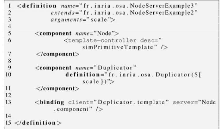
This additional template layer is implemented as shown on Listing 10, which reuses the previous definition to which it adds a variable number of Node components. Lines 1-3 as-signs a name to the resulting architecture, explicits which architecture is extended, and defines the “scale” parameter which is the number of Node components to be instantiated. Lines 5-7 describe the Node component to which the tem-plate feature is added. Lines 9-11 describe the factory com-ponent “Duplicator” whose definition is described in the file Duplicator.Fractal. This definition describes a prim-itive component with a client interface “template” to the non-functionnal replication service. We see in line 10 that the pa-rameter “scale” is passed to the factory component Duplica-tor. Line 13 connects the “template” interface of the factory
1 <d e f i n i t i o n name= ” f r . i n r i a . o s a . N o d e S e r v e r E x a m p l e 3 ” 2 e x t e n d s= ” f r . i n r i a . o s a . N o d e S e r v e r E x a m p l e 2 ” 3 a r g u m e n t s= ” s c a l e ”>
4
5 <component name= ” Node ”>
6 <template−controller desc=” s i m P r i m i t i v e T e m p l a t e ” /> 7 </component> 8 9 <component name= ” D u p l i c a t o r ” 10 d e f i n i t i o n= ” f r . i n r i a . o s a . D u p l i c a t o r ( ${ s c a l e}) ”> 11 </component> 12
13 <b i n d i n g client= ” D e p l i c a t o r . t e m p l a t e ” server= ” Node . c o m p o n e n t ” />
14
15 </ d e f i n i t i o n >
Listing 10. Model architecture with loop
component (Duplicator) to the “component” interface of the Node (it exists in all Fractal components). At runtime, dur-ing the initialization, the factory component Duplicator dupli-cates “scale” times the component connected to its “template” interface. The factory component Duplicator duplicates and binds new components in the same way as the original tem-plate component.
2.5.
Multi-occurence patterns
In [6], we presented the concept of multi-occurrence and demonstrated its feasibility in the DEVS formalism; we also presented few modelling patterns to demonstrate its useful-ness. This multi-occurrence feature is inspired from the con-cept of shared component found in the FCM. The idea of a shared component is that of a component instance that can be found repeated in multiple places in a hierarchical archi-tecture, but with the same internal state (ie. the same internal state is shared by all the occurrences). This kind of compo-nent breaks a bit the intuitive notion of self-contained black-box, since a component behavior receives influences from all the places where it is shared. However, has demonstrated in [6], this construction can prove to be very useful and help to significantly improve reuse-ability of models.
In practice, in FractalADL, the first occurrence of a shared component is declared as a normal component. Then, subse-quent occurrences are declared by giving a path relative to the first occurrence in the component hierarchy. Hence all the repetitions of the shared component do have not an equal im-portance: the first occurrence is a regular component while the remaining occurrences may be considered as proxy (a concept very similar to that of a “symbolic link” in Unix-like operating systems).
3.
EXAMPLES OF USE
In order to better illustrate the usefulness and relevance of the features introduced in the previous section, in the
follow-ing we give two examples: the first one, in Section 3.1., illus-trate the potential of the overloading feature for building sim-ulation scenarios; the second one, in section 3.2., illustrates the potential use of multi-occurrence for building shortcuts in models to lower the computational complexity of a simula-tion.
3.1.
Advanced scenarios using overloading
EE A B Scenario Model Scenario X Model C EE A C B
X
Figure 3. Reuse and adapt a model of reference.
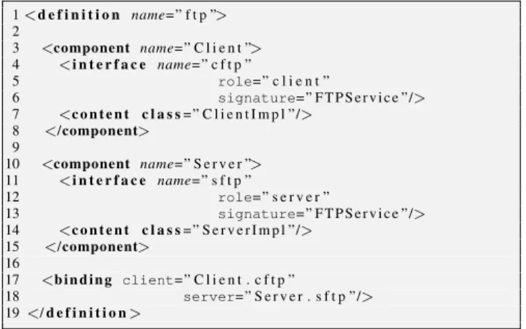
We present hereafter a case study to illustrate the poten-tial usage of the overloading feature for building scenarios: we build an advanced scenario reusing existing component models that are only available in compiled form, at execution level (for example because it came after a long validation and verification process, or because we want to keep the source code secret). Figure 3 shows the composition of the complex scenario and the reference model. The reference model con-tains two components A and B. The complex scenario adds a new component C between A and B, and a new component EE which generates exogenous events. The composition is the result of the model and the scenario. In order to build such a composition we use the overloading feature of FractalADL. To illustrate this kind of composition we build a practical ex-ample: a small security case study based on a reference model in which a user establishes an FTP session with a server using
1 <d e f i n i t i o n name= ” f t p ”> 2 3 <component name= ” C l i e n t ”> 4 <i n t e r f a c e name= ” c f t p ” 5 role= ” c l i e n t ” 6 signature= ” F T P S e r v i c e ”/> 7 <c o n t e n t c l a s s= ” C l i e n t I m p l ”/> 8 </component> 9 10 <component name= ” S e r v e r ”> 11 <i n t e r f a c e name= ” s f t p ” 12 role= ” s e r v e r ” 13 signature= ” F T P S e r v i c e ”/> 14 <c o n t e n t c l a s s= ” S e r v e r I m p l ”/> 15 </component> 16 17 <b i n d i n g client= ” C l i e n t . c f t p ” 18 server= ” S e r v e r . s f t p ”/> 19 </ d e f i n i t i o n >
Listing 11. FractalADL definition used to implement layout of figure 4.
the unsecured version of the protocol. The case study consists in simulating a Man-In-The-Middle attack (MITM) in which an Adversary is able to intercept the traffic flows in both di-rections between the client and the server.
ClientImpl
ServerImpl
Client
Server
cftp
sftp
Figure 4. Components layout of File Transfers Protocol case study.
First, we assume that we have existing models of the client and the FTP server. It is worth emphasizing that none of these existing models has been initially developed to be used in this study; therefore, we will assume that we are not supposed to have the source code of these components. Figure 4 shows the architecture of the model, and Listing 11 details its im-plementation in FractalADL. Line 1 names the model, lines 3-8 describe the client and lines 10-15 the server. Lines 17-18 represents the binding that connects the client to the server.
The protocol represented by this model is a two-party pro-tocol. We will denote the two parties by the name Client and Server (Client want to be authenticated on Server).
From the original model above described, we want to de-rive a man-in-the-middle attacker scenario. Hence we need to introduce a third party Adversary. All the communication between Client and Server are intercepted by the Adversary. Thus both Client and Server talk to Adversary and cannot communicate directly with each other. The Adversary for-wards the information between Client and Server, but - it’s the security break - but it may read, change, or drop any com-munication.
ClientImpl
ServerImpl
Client
Server
cftp
sftp
AttackerImpl
asftp
acftp
Attacker
Figure 5. Components layout of Fractal’s MITM attack.
1 <d e f i n i t i o n name= ” mitm−f t p ” e x t e n d s =” f t p ”> 2 <component name= ” A d v e r s a r y ”> 3 <i n t e r f a c e name= ” a c f t p ” 4 role= ” c l i e n t ” 5 signature= ” F T P S e r v i c e ”/> 6 <i n t e r f a c e name= ” a s f t p ” 7 role= ” s e r v e r ” 8 signature= ” F T P S e r v i c e ”/> 9 <c o n t e n t c l a s s= ” A d v e r s a r y I m p l ”/> 10 </component> 11 12 <b i n d i n g client= ” C l i e n t . c f t p ” 13 server= ” A d v e r s a r y . a s f t p ”/> 14 <b i n d i n g client= ” A d v e r s a r y . a c f t p ” 15 server= ” S e r v e r . s f t p ”/> 16 </ d e f i n i t i o n >
Listing 12. FractalADL definition used to implement layout of figure 5 reusing (extending) the previous definition of Listing 11.
Figure 5 show the new architecture we want to obtain. Since model is locked, we cannot change his topology di-rectly in source code. Listing 12 shows how to use the Frac-talADL overload capability to overload the topology. Line 1 shows that we extend the original ftp model in a new model called mitm-ftp. Line 2-9 represent the declaration of the new Adversary component. And lines 11-14 demonstrate how the original bindings between Client and Server can be over-loaded by a new binding between Client and Adversary, and between Adversary and Server. With this topology, the com-munications between the Client and the Server go through the Adversary.
This example shows how to modify a model to include new component or change topology. The overload capability of Fractal ADL permit to reuse and change some specification of the model like topology. In fact, in our example, commu-nication between the Client and the Server go through the Ad-versary but the FTP model have not been modified. We build a new model extending the original FTP model, and overload the binding between the Client and the Server.
3.2.
Shortcuts based on shared components
The shortcut modeling pattern consists in using a shared component to build interaction shortcuts between distinct components. This construction may be used to shorten the interaction path between multiple components, and hence re-duce the simulation complexity of the model (see for example [11] for a definition of the simulation complexity).
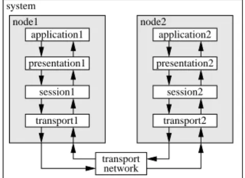
It is worth stressing that the main goal of this shortcut is to create an interaction that does not physically exist in the real system: this fake interaction is only added in order reduce the simulation complexity where the corresponding simpli-fication is assumed to not have a significant impact on the output of the simulation. This kind of shortcut applies well to layered architectures, such as networks, in which peers at a given level need to use the services of lower layers to com-municate with each other instead of directly exchanging mes-sages. system transport network node1 node2 application1 presentation1 session1 transport1 application2 presentation2 session2 transport2
Figure 6. Two interconnected nodes communicating using an OSI-like layered protocol stack.
The shortcut modeling pattern consists in applying the transformation illustrated by Figure 7 everywhere a short-cut end-pointis needed (the figure only shows the transfor-mation for application1, but a similar transfortransfor-mation is required for application2). The application1 inner component is the same as the original one described in Fig-ure 6; the app-sc-wrapper1 is a new wrapping hierar-chical component that replaces the application1 compo-nent in the original model of Figure 6 (both compocompo-nent have exactly the same interfaces); the app-shortcut compo-nent is a shared compocompo-nent that provides an alternate shorter path (hence the shortcut name) between every component in which it is plugged in. The decision to use this shorter path or not to use it is taken dynamically, for every packet, by the
app-switch-filter1component.
Thanks to this construction, an outgoing packet from the application1inner component will either be directed to-ward the realistic path (the one with high simulation complex-ity) toward the presentation1 component, or toward the less realistic path through the app-shortcut component.
application1 app−switch−filter1 app−shortcut app−sc−wrapper1 node1 presentation1 shared low layers...
Figure 7. The shortcut modeling pattern applied to the
application1component. (The same modification is
ap-plied to application2, but is not shown here.)
Compared to DS-DEVS, the dynamic structure variant of DEVS, notice that the decision to use the shortcut for a partic-ular packet does not mean that subsequent packets will have also to use the shortcut. Since both paths are needed at any time, the need here is not for a dynamic change of structure, but for the simultaneous availability of both structures.
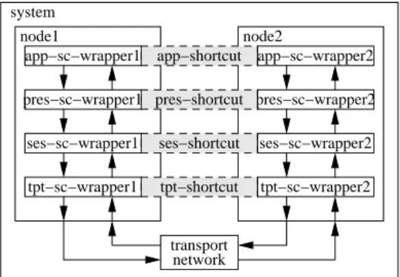
transport network system node1 app−sc−wrapper2 pres−sc−wrapper2 ses−sc−wrapper2 tpt−sc−wrapper2 app−sc−wrapper1 pres−sc−wrapper1 tpt−sc−wrapper1 node2 ses−sc−wrapper1 pres−shortcut ses−shortcut tpt−shortcut app−shortcut
Figure 8. The shortcut modeling pattern may be applied (in-dependently) to each level of a protocol stack.
This construction may be applied several times in the same model. For example, as shown on Figure 8, this shortcut construction may be applied to each of the four compo-nents that model a network layer: the application, as al-ready described in Figure 7 but also the presentation, the session and the transport ones. In each case a new dedicated “switch-filter” component needs to be imple-mented.
Therefore, this shortcut modeling pattern provides a pow-erful mean for adjusting the simulation complexity of a model. However, deciding in which cases it is relevant to use the shortcut path and in which cases it is not, is a difficult question because it strongly depends on the model and the simulation goals (this question is not further addressed in this paper).
4.
CONCLUSION
In this paper, we describe a few advanced features for Ar-chitecture Description Language that we strongly recommend for inclusion in a DEVS implementation standard. These fea-tures come from the FractalADL Library, a reference library for building FCM-based software architectures.
Since the FCM is the (general purpose) component frame-work on top of which our Open Simulation Architecture (OSA) is built, we can state a few important facts to assess the relevance of these features in the current DEVS standard-ization effort:
• Because they have been used in OSA, these features have been successfully used in actual simulations; • Because the FCM is a general purpose component model
and it has been used in large applications, these features, except the modified template feature, have been success-fully used multiple times with success; it is also worth mentioning that the FCM is a specification that have been implemented in multiple programming languages, including Java and C/C++;
• OSA is a general purpose discrete event simulation ar-chitecture which is not exclusively devoted to the simu-lation of DEVS models; however, OSA is primarily de-signed for reuse, and as a matter of facts, DEVS engines such as the JAMES II DEVS simulation engine and re-lated JAMES plugins have been successfully integrated in the OSA architecture.
These facts show that these features have been successfully implemented and tested multiple times, in DEVS simulations, as well as in non DEVS simulations or in general-purpose component-based applications. We claim that these features have proved to be useful for DEVS simulations, and have reached a sufficient level of maturity to be considered for in-clusion in a DEVS standard.
DEVS provides a strong formal background, which allows the non-ambiguous definition of components, but it lacks an implementation specification, which happens to be criticized. However, it should be noted that this lack of constraints cer-tainly explains a large part of the success of the DEVS. With respect to this issue, the philosophy of Fractal could bring in-teresting answers. Indeed, the philosophy of Fractal is to of-fer a maximum of flexibility, which results in allowing almost everything to be changed in a given Fractal implementation. Hence, by forcing its users and developers communities to rely on versatile tools, the FCM gives space for alternative im-plementations while still providing a federating model. While inter-operability requires a set of clear and well-defined APIs, diversity tends to require the opposite. Hence, the difficult is-sue to solve in the current standardization process is certainly to find the best balance between these two conflicting direc-tions.
REFERENCES
[1] N. Medvidovic and R. Taylor, “A classification and comparison framework for software architecture de-scription languages,” Software Engineering, IEEE Transactions on, vol. 26, no. 1, pp. 70–93, 2002. [2] E. Bruneton, T. Coupaye, and J. Stefani, “The
fractal component model specification.” Available from http://fractal.objectweb.org/specification/ [Last accessed: 11/30/2010], February 2004. Draft version 2.0-3.
[3] O. Dalle, “Component-based discrete event simulation using the Fractal component model,” in AI, Simula-tion and Planning in High Autonomy Systems (AIS)-Conceptual Modeling and Simulation (CMS) Joint Con-ference, (Buenos Aires, AR), Februray 2007.
[4] O. Dalle and C. Mrabet, “An instrumentation frame-work for component-based simulations based on the separation of concerns paradigm,” in Proc. of 6th EU-ROSIM Congress (EUEU-ROSIM2007), (Ljubljana, Slove-nia), September 9-13 2007.
[5] J. Ribault and O. Dalle, “Enabling advanced simulation scenarios with new software engineering techniques,” in 20th European Modeling and Simulation Symposium (EMSS 2008), (Briatico, Italy), 2008.
[6] O. Dalle, B. P. Zeigler, and G. A. Wainer, “Extending DEVS to support multiple occurrence in component-based simulation,” in Proceedings of the 2008
Win-ter Simulation Conference (S. J. Mason, R. R. Hill, L. M¨onch, and O. Rose, eds.), Dec. 2008.
[7] J. Ribault, O. Dalle, D. Conan, and S. Leriche, “OSIF: a framework to instrument, validate, and ana-lyze simulations,” in Proceedings of the 3rd Interna-tional ICST Conference on Simulation Tools and Tech-niques, pp. 1–9, ICST (Institute for Computer Sciences, Social-Informatics and Telecommunications Engineer-ing), 2010.
[8] J. Ribault, Reuse and Scalability in Modeling and Simu-lation Software Engineering. PhD thesis, University of Nice - Sophia Antipolis, France, 2011.
[9] E. Bruneton, T. Coupaye, M. Leclercq, V. Qu´ema, and J.-B. Stefani, “The Fractal Component Model and Its Support in Java,” Software—Practice and Experience, special issue on Experiences with Auto-adaptive and Reconfigurable Systems, vol. 36, pp. 1257–1284, Sept. 2006.
[10] O. Dalle, “The OSA Project: an Example of Compo-nent Based Software Engineering Techniques Applied to Simulation,” in Proc. of the Summer Computer Sim-ulation Conference (SCSC’07), (San Diego, CA, USA), pp. 1155–1162, July 2007. Invited paper.
[11] B. P. Zeigler, H. Praehofer, and T. G. Kim, Theory of Modeling and Simulation. Academic Press, Inc., 2000.