Applying Set Based Methodology in Submarine Concept Design by
Matthew C. Frye
B.S. Mechanical Engineering, Virginia Military Institute, 2001
Submitted to the Department of Mechanical Engineering and the Engineering Systems Division in Partial Fulfillment of the Requirements for the Degrees of
Naval Engineer MASSHUSETS INSTTTE
and CHNOLOGY
Master of Science in Engineering and Management
SEP 012010
at theMassachusetts Institute of Technology
LIBRARIES
June 2010
ARCHiVES
C 2010 Massachusetts Institute of Technology. All rights reserved.
Signature of Author
Department of Mechanical Engineering and System Design and Management May 7,2010
C e r ti f i e d b y / / \ D a n F r e y
Associate Professor of Mechanical Engineering d Engineering Systems Thesis Supervisor
Certified by __ _ _ _ _ _ _ _ _ _ _
C by Patrick Hale
Director, System Design and Management Fellows Program Engineering Systems Division
/1
-Accepted by O ,rW
David E. Hardt Chair, Departmental Committee on Graduate Students Department of Mechanical Engineering
Applying Set Based Methodology in Submarine Concept Design By
Matthew C. Frye
Submitted to the Department of Mechanical Engineering on May 7, 2010 in Partial Fulfillment of the Requirements for the Naval Engineers Degree and Master of Science in System Design and Management ABSTRACT
Early stage ship design decisions continue to be a challenge for naval architects and engineers. The complex interactions between the different elements of the ship and the broad spectrum of disciplines required in ship design make it difficult to fully realize the effects and limitations early decisions place on design flexibility.
Naval ship design has primarily focused on using point based design methods that do not necessarily produce the most cost effective, innovative, and high quality designs.
Recognizing these shortcomings, U.S Navy design is exploring the use of Set Based Design (SBD) principles and methodology in designing the fleet for the 2 1s" century. Existing research has shown the merits of SBD in other industries; however, research on the use of SBD in naval design does not exist.
The thesis explores how to execute SBD in light of the recent restructuring of the U.S. Navy acquisition process calling for the use of SBD in pre-preliminary design. This is undertaken using the knowledge gained from exploration of the Ship-to-Shore Connector (SSC) program, the first use of SBD in a new start acquisition program.
The thesis concludes by applying the derived information to an early stage submarine concept design. This effort focused on how to develop submarine design parameters and exploration of how to create and reduce integrated concepts.
Thesis Supervisor: Dan Frey
BIOGRAPHICAL NOTE AND ACKNOWLEDGEMENTS
Matthew Frye is a Lieutenant in the U.S. Navy. He received his B.E. from Virginia Military Institute in Mechanical Engineering in 2001. Commissioned as an Ensign in the U.S. Navy from Officer Candidate School, he is qualified in submarines and served three years aboard the USS CHEYENNE (SSN 773). He transferred into the Engineering Duty Community where he will design, maintain, and acquire submarines for the U.S. Navy. The author would like to thank Dan Frey for taking the time to provide advice, ideas, and encouragement leading to the success of this project. Thanks are also due to CAPT Mark Welsh for providing leadership and direction throughout all the coursework at MIT. Sources outside of MIT that provided much needed resources and information include Peter Canning, Senior Naval Architect at Electric Boat, Groton, CT. Also, Dave Singer and Mike Buckley are owed a great deal of thanks for their information in regards to Set Based Design.
Table of Contents
List of Tables ... 9
List of Figures...9
1.0 Introduction...11
1.1 W hat is Set Based D esign?... ... ... ... . . 11
1.2 M otivation for Research ... 11
1.3 Objective and Outline of Thesis ... 13
2.0 D esign Process Background ... 15
2.1 Evolution of Ship D esign M ethods and Practices ... 15
2.2 D efining Set Based D esign Principles... 16
2.3 D efining the V alue of SBD ... 17
2.4 W here does Set Based D esign fit in?... ... ... ... ... . . 22
2.5 Leveraging Set Based Design in the Acquisition Process ... 23
3.0 Exploring the use of SBD on development of the SSC ... 25
3.1 W hat is the SSC program ?... ... ... ... . . 25
3.2 SBD V ocabulary... 26
3.3 SBD role in the SSC Prelim inary D esign ... 27
3.4 SBD Hurdles ... 34
3.5 D esign Process Results... 34
3.6 SBD success...35
4.0 D efining the SBD Fram ew ork ... 39
4.1 Fram ew ork Sum m ary ... 39
4.2 Organizational Structure ... 40
4.3 Process M ap...41
4.4 Set D evelopm ent... 41
4.4.1 Element Definition and Variable/Range Selection...42
4.5 N arrow ing the Set Trade Space ... 43
4.5.1 Elem ent Specific Exclusion... 43
4.5.2 Com bination Specific Exclusion ... 45
4.6 Final Screen for Balancing ... 45
4.8 Concept Scoring... 48
5.0 Executing SBD in a Subm arine Concept Design ... 51
5.1 Subm arine D esign Background ... 51
5.2 Design Setup: Requirem ents... 53
5.3 Set Developm ent... 54
5.3.1 Elem ent D efinition and Variable/Range Selection... 55
5.4 N arrow ing the Set Trade Space ... 56
5.4.1 Elem ent Specific Exclusion... 57
5.5 D eveloping Balanced D esigns... 58
5.5.1 Balance Filter... 59
5.6 Concept Scoring... 65
6.0 Conclusion ... 67
6.1 The Future of Subm arine Design... 67
6.2 Suggestions for Im plem entation... 69
6.3 Areas for Future Study... 69
References...---71
Appendix A : SSC Program Process M ap ... 73
Appendix B: SSC Program Attributes and M easures...77
Appendix C: Initial Submarine Elements/Factors/Options ... 78
List of Tables
Table 1: Auxiliary Trade Space Summary ... 30
Table 2: Initial Element/Factor/Option Summary for SSC ... 30
Table 3: Reduced Auxiliary Trade Space Summary ... 31
Table 4: Reduced Element/Factors/Options Summary for SSC...32
Table 5: Hull Element Trade Space...56
Table 6: Hull Element Reduction Effort... 58
Table 7: Design Factors and Options... 60
Table 8: Example Integrated Concept Factor/Variable Summary... 64
Table 9: Integrated Concept Output Summary from Balance Filter...64
List of Figures
Figure 1: Designed in Costs [1]... 19Figure 2: Evolution of Design Knowledge [1] ... 20
Figure 3: Areas of SBD Impact [1]...21
Figure 4: Navy Acquisition 2 Pass, 6 Gate Acquisition Process and Stages of Design ....22
Figure 5: US Navy LCAC ... 25
Figure 7: SBD Process for the SSC ... 28
Figure 8: Diagram of the SSC Balance Loop Process... 33
Figure 10: SBD Framework Model...39
Figure 11: Virginia Class Design Modules ... 40
Figure 12: Submarine Design Phases ... 51
Figure 13: B alance Filter ... 59
Figure 14: Balance Filter Volume Module ... 61
Figure 15: Balance Filter Weight Module ... 62
1.0 Introduction
Submarine design is one of many engineering design activities that involve complex relationships ranging from satisfying customer design requirements to detailed design drawings created for manufacturing. With the dearth of information available in
textbooks and across the internet, one can readily find information on submarine design and engineering practices. Much of this information follows from historical design methods such as point based approaches and building block methods. This paper seeks to add to the body of existing work by exploring a methodology, Set-Based Design (SBD), and its application in the concept exploration phase of submarine design. Much of the work will center on U.S. naval design and all information contained within is obtained
from open sources.
1.1 What is Set Based Design?
SBD has become a recognized design methodology (based on the study of Toyota Motor Corporation described in Chapter 2) and as summarized by Bernstein, "While set- based concurrent engineering [set based design] consists of a wide variety of design techniques, the basic notions can be stated in two principles: 1) engineers should consider a large
number of design alternatives, i.e., sets of designs, which are gradually narrowed to a final design, and 2) in a multidisciplinary environment, engineering specialists should independently review a design from their own perspectives, generate sets of possible solutions, and then look for regions of overlap between those sets to develop an integrated final solution." [1]
1.2 Motivation for Research
Failures in ship programs have been traced to a host of factors including failures in the design process, unrealistic expectations, changing requirements, etc. The traditional design process has succumbed to these issues because historical methods are not inherently capable of managing the complexity of large-scale product design. Success has been achieved in the past; however, it often came at the hands of individual efforts to push through the existing design environment and process hurdles. In design
environments where many of the critical skills and experience of the U.S. naval design community have been lost, the transition to younger designers prevents the reliance on personnel experience and capabilities. The ability to capture created knowledge that can be imparted later in the design or potentially many years later would alleviate such issues.
This transition is happening at a time when the already complex nature of ship design is seemingly becoming more complex. This can be owed to component and equipment advances and high technology refresh rates. Employing innovation in new designs requires understanding the potential tradeoffs and interface management. Thus, there is a need to explore multiple options and provide a sound framework to compare integrated concepts.
These are only a couple of the concerns in the future naval design environment. One not previously discussed, but potentially the most important is the budget. Naval design operates within the confines of the Department of Defense (DOD) acquisition process. Acquisition is an incredibly regulated activity and although reform in that area is beyond the scope of this thesis, the manner in which a design is approached has direct
connections in creating a better system. In an era where limited budgets, emerging technology, and evolving mission capabilities complicate the design space, solutions to these issues come in many forms.
Naval design has experienced an evolution of design methods and practices. The use of Integrated Product Teams (IPT) is one such example. Keane et. al. discuss the critical need to extend this effort beyond detailed design phase to produce a collaborative product development environment with the hopes of providing a solution to some of the Navy's critical cost and future design issues. [3] In the current design environment, new methods
for design communication, integration, and information transfer are needed.
SBD represents one such method; however, the ability to transition into an environment where a new methodology can be implemented requires a large amount of work such as:
" Determining what platforms SBD can be implemented on? [Where]
" When can SBD be used? [When]
e How is SBD executed? [How]
* What is the real (versus hypothetical) value in SBD? [Validation]
The list above is only a few of the many concerns and questions surrounding SBD implementation. Research in this area seeks to answer existing questions which will undoubtedly uncover new ones.
1.3 Objective and Outline of Thesis
The goal of this thesis was to explore how to execute SBD recognizing the recent
restructuring of the DOD acquisition process calling for its use in pre-preliminary design. This is then applied to an early stage submarine concept design in order to:
1) Provide a framework for trade space exploration.
2) Determine best method and practices for screening of design factors.
3) Develop a method for design parameter integration that can be used to selectively reduce the number of integrated concepts.
This task was undertaken through looking at SBD applications in a naval design
environment. Although this research contains discussions of other design methodologies, the goal of the research was not to expound upon the virtues of SBD. Rather, this work aims to focus on the execution side (how, when, and if's) of SBD. Any discussion that includes commentary in regards to the advantages of SBD is intended to provide context for the methodology.
Chapter 2 discusses where SBD fits in within the naval acquisition process, potential value it brings to the table, and what one could expect from its use. This section concludes with a general discussion of how to apply SBD.
The thesis continues by looking at the Ship-to-Shore Connector (SSC) program, the first use of SBD in a new start acquisition program, and is contained in Chapter 3. The knowledge gained from exploration of the program and the lessons learned from the SSC program provide guidance on how to execute SBD, how SBD interacts and fits in with the plethora of naval design guidance documents, and what hurdles and issues that arose throughout that design effort. Commentary is included on the success and failures the program achieved using SBD.
Chapter 4 follows by taking the information garnered from the SSC program and developing a framework that can be used for naval applications. This framework identifies general steps for concept exploration with details provided on methods for executing these steps.
Chapter 5 looks at applying elements from the developed framework to the submarine concept exploration process. In particular, this section identifies how the "sets" are defined (elements, attributes, and ranges), the process by which these sets are narrowed, and how to develop integrated concepts. Additionally, how to use SBD principles to facilitate requirement development and traceability is included.
The thesis concludes by looking at methods to facilitate the transition to SBD by looking at the early stage design processes of the OHIO Class replacement program. Advanced concepts in SBD are noted and areas for future work identified.
2.0 Design Process Background
Prior to exploring a shift to a new design paradigm, one must first look at the evolution of naval design practices which has historically been characterized by a spiral design
approach. SBD is then introduced and its role in the ship design process is discussed. This sets the stage for discussion of the use of SBD in the SSC program.
2.1 Evolution of Ship Design Methods and Practices
The traditional approach to developing ship designs utilized a process dubbed the "design spiral" as published by J. Evans in 1959. This model recognizes the complex nature of ship design and approaches the design process from the view of conducting iterative passes from one element to the next: weight, volume, structure, stability, resistance, powering, trim, etc. By systematically addressing each element in sequence and doing so in increasing detail in each pass around the spiral, a single balanced design which
satisfies all constraints can be reached. This approach to design is synonymous with the term point based design since each pass through the spiral attempts to resolve conflicts between elements and develop a design that meets requirements. The result is a base design that is feasible but not typically a global optimum. Another disadvantage is that the number of iterations around the spiral is generally limited by the available time and budget with the design often considered complete when the design period has reached the end of its scheduled time.
The highly iterative nature of point based approaches has evolved over time. One such evolution is concurrent engineering (CE). In CE, a point based design approach is still implemented but the integration of development teams allows engineers to analyze design facets in parallel and helps in design communication. [1] These cross functional teams, or IPTs, allow for faster feedback and flows of information. IPTs, discussed below, were utilized heavily by in the VIRGINIA (VA) class submarine design process. Communication is further enhanced through collocation. Collocation shortens the design processes and mitigates the errors due to limited intra-team communication caused by
distance. The increased complexity of designs in many industries has driven the CE push; however, it does not change the fundamental point design process. [1]
The development of the VA class submarine used a multidisciplinary team-based concurrent engineering approach. Integrated Product and Process Development (IPPD) teams brought the combined experience of the shipbuilders, vendors, designers,
engineers, and ship operators to bear on the ship design.[4] IPPD is a concurrent approach to developing all the life cycle processes necessary to design, build, operate, and maintain the craft at the same time the craft is being developed. Thus, IPPD is a multi-disciplinary integration and teamwork approach based on the use of IPTs involving the life cycle process stakeholders in the design of the craft. IPTs are project specific
groups consisting of designated personnel from stakeholder organizations whose participation ranges from a full-time commitment to ad-hoc representation to address specific issues. Specifically for the VA class submarine project, the IPT structure
facilitated decision-making and product development. The IPT approach took advantage of all members' expertise. The early involvement of production personnel on these teams ensured a match between the design and the shipbuilder's construction processes and facilities, allowed a smoother transition from design to production, and reduced the number of engineering change orders typically required during lead ship construction.
The IPPD approach has been augmented with an additional methodology, Design-Build-Test (DBT) which is a repetitive iterative approach based on designing concepts, testing concepts, and improving concepts based on testing. DBT facilitated the integration process.
2.2 Defining Set Based Design Principles
What is known about the principles as well as execution of SBD is derived in large part to the significant body of research involving the Toyota Motor Corporation; a car
manufacturer that created a strategy coined "set based development" and has become one of the car industry leaders. [5] Traditional product development wisdom dictates the early selection of a single design in order to freeze interfaces between product subsystems so
that team members can work effectively in parallel. This would seem to result in more productive product development effort. This makes sense considering that uncertainty in product development projects creates significant challenges for managers who strive to increase product quality, while reducing development time and costs. Toyota has however capitalized on its ability to converge to a final preferred concept in a manner
which does not restrict the trade space early on and actually uses delayed decision making and "sets" with variable ranges to explore the trade space. Once information becomes available to the designers at stages further along the design path, decisions are then made on what alternatives to eliminate. Remaining concepts continue in
development until additional information and studies are performed. These principles are not only applied to the design itself but also to the engineering requirements. Thus, Toyota develops a variety of concepts which would meet a range of requirements. [5] The main features of this design process are summarized as follows:
" Broad sets of design parameters are defined to allow concurrent design to begin. " These sets are kept open longer and explored in greater detail than typical to more
fully define tradeoff information.
" As the sets narrow, the level of detail (or design fidelity) increases.
* The sets are gradually narrowed until a more globally optimum solution is revealed and refined.
This was characterized by Alan Ward as set-based design. It differs from point-based design where critical interfaces are defined by precise specifications early in the design so that subsystem development can proceed. Often these interfaces must be defined, and thus constrained, long before the needed tradeoff information is available, inevitably resulting in a sub-optimal overall design.
2.3
Defining the Value of SBD
There is no arguing the success that Toyota has experienced; however, clearly linking this success to the use of a SBD mentality requires looking deeper into the Toyota design
process. This begins by studying the balance between manufacturing and design
processes. At first, they seem to be counter intuitive. This has been written and discussed by multiple sources and is dubbed the first Toyota paradox and is associated with Toyota in its Lean Manufacturing System and just-in time inventory. The paradox comes in the form that during the 1980's, Toyota did not follow traditional manufacturing approaches. Traditional manufacturing practice holds that economy of scale is the best path to better products at lower cost: one minimizes price by maximizing machine speed and capacity while neglecting the impact of space, transportation, and inventory; however, Toyota operated with little to no inventory and manufactured vehicles at a lower cost with better quality.
A second paradox, described by Ward et. al., lies at the foundation of the SBD concept and demonstrates how even though Toyota severely delays critical design decisions when
compared to other auto manufacturers, their time to market is shorter than the
competition. [6] Delaying decisions has the initial undesirable consequence of carrying along design alternatives that will be trimmed later on directly resulting in greater cost and man-hours up front. Delaying decisions, however, allows the design team to make decisions when more knowledge has been acquired. This provides designers and
engineers greater influence on the design space as it is defined in greater detail and ideas on cost are more clearly understood.
This highlights the first major area where SBD has impact: Cost. A major problem in U.S. naval design practices (if not in many product development organizations) is that early in the design process, cost estimates on the final product are made and a budget is created that attempts to match the initial cost. This happens even though the major portions of the total ship cost are not incurred until much later in the design process. SBD
strives to reduce the Committed Costs to more closely follow the Incurred Costs. The work of Bernstein illustrates this mismatch.
Percent of Lifetime Product Cost Committed Cost Incurr ed Costs 40 60 so 100
End ofConepua Design Producrion
Figure 1: Designed in Costs [II
Late in the design cycle, the ability to affect cost is significantly decreased and often times, the ability to pull money from one source and reallocate is not possible.
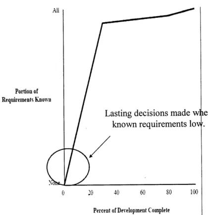
This follows with the next major area where SBD has impact: Knowledge. In any design, knowledge increases over time. The ability to leverage this fact and take full advantage is not something traditional design practices have been able to accomplish. Early design decisions are made by the engineers and managers even though the customer is not sure what they want and the details of the design are not well defined, developed, or
understood. Consequently, the decisions made during these stages are done so with incorrect and incomplete data. As the design evolves over time the engineers, managers and customer better understand, due to analysis and experience, the product and the requirements that are driving the product design.
Portion of Requirements Known
Lasting decisions made when known requirements lov.
N
20 40 60 so 100
Percent of Development Complete
Figure 2: Evolution of Design Knowledge [11
One area remains where SBD has impact: Stakeholder Influence. As touched on before, the initial stages of the design process are where stakeholders can have the greatest
impact. At this stage, the design and its requirements can be considered a blank canvas and thus any decision made has a direct impact on the final product performance and cost. As the design proceeds, the ability to impact the design diminishes because the design becomes more locked in and any major change, cost prohibitive. This ultimately results in the following figure which illustrates the desire to delay cost commitment and increase stakeholder influence late in the design while recognizing the
100 Knowledge (not changeable) -804- . -so - /Commnitted/ Management Influence 40 4 4 0 /
V:
/ 0 20 40 60 so 100Percent of Development Complete
Figure 3: Areas of SBD Impact [1]
As stated earlier, the goal underpinning the use of SBD is the delay of critical decisions to the latest point possible. By delaying decisions, one can improve the design by
delaying the commitment of cost until later in the design process and until such time that information is much better. By delaying the cost commitment one also increases the time in which stakeholders can influence a design.
Much of the research done on Toyota has demonstrated how they were able to achieve a competitive advantage using SBD. As noted earlier, the parallel development that exists in this type of environment requires additional resources which will incur greater up front cost. The danger here lies in the fact that if these cost were to be so large as to dominate the creation of value in the project, overall project success, particularly that tied to SBD principles, would be in jeopardy. Without understanding the underlying mechanisms at work, applying set-based development is fraught with risk. [7] Ford, et. al warns that a better understanding of the underlying causal relationships within this approach is needed for organizations to take maximum advantage while minimizing risk.
2.4
Where does Set Based Design fit in?
Although many organizations would like to emulate the success of Toyota, completely copying the model set forth by the company would not work in a number of industries namely U.S naval design. The nature of the car industry combined with the culture of the company makes it implementation in that form ideal.
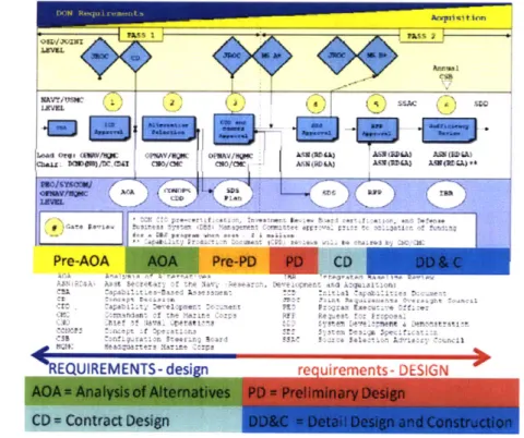
In a naval design application, matching a design methodology with that required to make ship design a process that is innovative, affordable, flexible, etc., requires matching the available inputs and outputs of steps throughout the process to the method that is used. These steps are defined in the DOD acquisition process which was implemented in its modified form in 2008 by the Secretary of the Navy. [8/9] The goal of the modification from its preceding form was to involve the appropriate stakeholders in the acquisition decisions at an earlier stage. As shown in Figure 1, the "2 Pass - 6 Gate" process, involvement begins with the Initial Capabilities Document (ICD) and continues through system development and demonstration.
EQUIREMENTS- design requirements- DESIGN
Figure 4: Navy Acquisition 2 Pass, 6 Gate Acquisition Process and Stages of Design
Figure 4 maps the traditional ship design stages onto the new process. Of particular note is the Pre-Preliminary Design (PPD) phase between the completion of the Analysis of Alternatives (AOA) and Preliminary Design (PD). SBD is anticipated to provide the greatest benefit during this phase as the general inputs and outputs in its use fit both the AOA and PD.
In the past, the outcome of an independently conducted AOA was a preferred alternative, or at most two or three alternatives, that would proceed into a PD. This has not been the case in the last few years as the AOAs for LHA(R), MPFF, and CG(X) did not produce a preferred alternative that the Navy proceeded to produce. For LHA(R) and MPFF, the final acquisition alternative implemented was not part of the recommended solution set coming out of the AOA.[10/11] For CG(X), the final acquisition alternative had not been selected a year after the originally scheduled completion of the AOA and final program cancellation only recently occurred.[12] The AOAs essentially only managed to identify a range of possible solutions for a range of desired capabilities which as shown later works within the context of SBD but not in the realm of point based preliminary design. It was thus left to the Navy to further refine the requirements and solutions before the commencement of PD. This led to the new "2 Pass - 6 Gate" process which recognizes the need for PPD between Gates 2 and 3.
2.5 Leveraging Set Based Design in the Acquisition Process
PPD provides the opportunity to perform trade-offs among individual system
performance, total ship performance, requirements, the Concept of Operation (CONOPS) and cost. [13] Having recognized the inputs from the AOA may or may not provide a solid context or guidance for PD, PPD provides an opportunity to use SBD methodology where the plethora of activities performed by the wide range of geographically dispersed organizations presents a challenge for standard design doctrine.
By the completion of PPD, performing SBD in parallel with the development of a Capabilities Development Document (CDD)I allows for an earlier and more informed exploration of feasible requirements as specified in the CDD. This essentially leads to delaying decisions until requirements are better understood and helps the designers understand the impact of the requirements. This eventually leads to a fixed set of requirements that are derived with a total ship impact in mind. The ship design then proceeds at a level of detail where a quality cost estimate can be performed.
This varies significantly from past, traditional design efforts where at the start of PD, the requirements for the ship are largely fixed and large changes are generally avoided. This is the case despite information or studies coming to light that may cast doubt on the applicability of early design decisions. SBD practice offers considerable flexibility as changes or decisions made later in the design process provide system refinement and narrow the trade space ultimately resulting in a design that converges.
1 A CDD provides operational performance attributes, including supportability, for acquisition personnel in
the military. It includes Key Performance Parameters (KPPs) and other parameters that guide the development, demonstration, and testing of the current increment. It also outlines the overall strategy for developing full capability.
3.0 Exploring the use of SBD on development of the SSC
The SSC program is the first ship/craft acquisition program to use SBD. Based on the scarcity of information available that discusses actual SBD implementation, exploration of its use in this program provides a framework in which to implement SBD in naval design. Some aspects of its implementation are sensitive in nature; however, discussion of those areas is not necessary for the purpose of understanding the SSC programs implementation of SBD. Much of the information contained in this section is contained from Reference 2 obtained from the SSC program office.
As compared to the Toyota method for applying SBD contained in Chapter 2, the SSC programs use of SBD was not part of the full concept/design/manufacturing life cycle. It was conducted in accordance with the PPD phase as noted in Chapter 2.
3.1 What is the SSC program?
The Ship-to-Shore Connector (SSC), as taken from its industry day announcement, is an Air Cushion Vehicle (ACV) that represents the future Navy craft for transporting
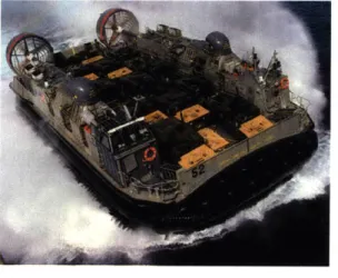
vehicles, cargo, and personnel from ship-to-shore and/or seabase-to-shore. It is the planned replacement for the current Landing Craft, Air Cushion (LCAC), shown in Figure 5, as these craft reach the end of their service life.
Figure 5: US Navy LCAC
(photo courtesy of blog.richardslowry.com/.../1/NAVYLCAC-1g.jpg)
... ... .....
SSC goals include providing high speed, over the horizon, heavy lift capability to transport personnel, equipment, and material for the United States Marine Corps' Marine Expeditionary Brigade (MEB). Like the LCAC, the SSC must have the ability to operate in the well decks of U.S. Navy amphibious ships, operate in planned amphibious and Maritime Prepositioning Force (MPF) ships, operate over beaches, ice, mud, and marsh areas, operate in inland regions, ascend varying beach gradients, and transport a cargo greater than 60 short tons.
Currently, the LCAC Service Life Extension Program (SLEP) started in 2002 is bridging the gap until the SSC is brought into the fleet. [14] For reference, the LCAC SLEP has a design payload of 70 short tons and maintains the available deck area of the LCAC. The SSC is intended to provide increased performance in the following areas: ability to operate in higher sea state conditions; increased payload, range, and speed; reduced crew; reduced maintenance and operational costs; and increased reliability and maintainability. The LCAC is scheduled for replacement by the SSC starting in the year 2019.
3.2 SBD Vocabulary
Terms key to an understanding of SBD are included below:
e Design Factor: A design factor (or design parameter and heretofore referred to as a factor) is an independent variable; it is something the designer can choose or influence to impact the design. In the SBD effort, all factors were initially assumed to impact the SSC design at the Craft level.
e Design Trade Space: The design trade space is defined by elements made up of candidate design factors.
e Element: An element describes a partitioned area of the trade space.
e Design Options: Factors are decomposed into design options (heretofore referred to as an option) that can either be a discrete or continuous range.
" Dominated Option (Combinations): A dominated option is one which has been determined to be inferior in all attributes to another. Those options left after the dominated options have been discarded are called non-dominated. This can also apply to combination of options within an element or across elements.
3.3
SBD role in the SSC Preliminary Design
The SSC program began in the fall of 2007. In light of the change to the new acquisition process and recent issues in translating the results from the AOA into PD, NAVSEA desired to implement a SBD effort in the PPD of the SSC program. The SBD effort operated within the SSC organizational structure utilizing IPTs. The design team was led by experienced naval architects and marine engineers from a number of organizations (NAVSEA, Warfare Centers, Academia, Contractors).
The organizational breakdown for the SSC program is located in Figure 6.
Figure 6: Design Integration IPT for SSC's SBD Effort
e Ship Design Manager (SDM): The lead system engineer on the project, this individual represents the design team in all matters with outside organizations.
e Design Integration Manager (DIM): This individual is responsible for facilitating
communication, decision making, and integration among all the elements.
* System Engineering Manager (SEM): These individuals represent the system expert in the specific element field.
y
C4N SEM Auxiliaries HSI SEMSEM
C4N Auxiliaries HSI
DSEM DSEM DSEM
C4N Auxiliaries HSI
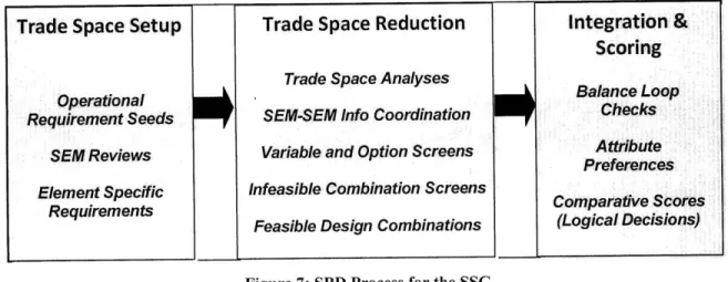
The effort began with the application of the Decision Oriented Systems Engineering (DOSE)2 method in order to design a SSC executable SBD process. DOSE was intended to help deal with the complicating and potentially conflicting demands, the guidance of the Navy System Engineering (SE) Guide and the Ship Design Manager's (SDM) Manual, directives to apply the Set Based Design methodology in conjunction with regression analysis techniques, and directives to support requirements traceability using Dynamic Object Oriented Requirements System (DOORS). The DOSE analyses resulted in an executable process compliant with the Navy SE guide. Although multiple views of the process exist, the following figure provides a summary of the activities at a level of detail required for process understanding.
Trade Space Setup Trade Space Reduction Integration & Scoring
Trade Space Analyses Balance Loop
Operational BlneLo
Requirement Seeds SEM-SEM Info Coordination Checks
SEM Reviews Variable and Option Screens Attribute
Preferences
Element Specific Infeasible Combination Screens
Requirements Comparative Scores
Feasible Design Combinations (Logical Decisions)
Figure 7: SBD Process for the SSC
With a process defined to apply SBD principles to the SSC Program, the next step was to describe the trade space so that the SBD process could be implemented. This involved translating the design issues into a formal trade space description. The method used to describe the trade space was a characterization scheme that provided for apportionment of factors, options, and operational constraints among the elements, or subsystems. As an
example consider the platform attribute speed. As an SSC platform attribute, speed is a function of skirt resistance, thrust, etc. Similarly, skirt resistance is a function of skirt materials and skirt material properties, including properties descriptive of the behavior of platform-specific skirt designs in specific sea states and coastal terrains. Expanding this example to include all platform level capabilities, a field of attributes, attribute ranges, 2 DOSE is a Systems Engineering method that can facilitate process design needs.
options, and component alternatives were developed that, taken together, spanned all derived element attributes and completely described the trade space to be explored.
The trade spaces were then analyzed at the element level. The SSC elements include Hull, Performance (Skirt), Machinery, Command, Control, Communications, Computers & Navigation (C4N), Auxiliaries, and Human Systems Integration (HSI). The selection of elements was not a product of the SBD effort, but rather this was the breakdown the project had initially intended to use. An example of the trade space summary for the auxiliary element is contained below in Table 1.
Auxiliaries Trade Space
Candidate Key Design Specific Options, Variable Ranges
Parameters of Study
Fire Suppression Options Self Contained Water Mist, Pump
Package Water Mist, Aerosol, C02
HVAC System Options Traditional Vapor Compression Cycle,
C02, Bleed-Air
Ventilation Enclosure Cushion Air, Dedicated Fan, Inductive
Options Ventilation
Fuel Tank Corrosion Fuel Bladders, Internal Paint Systems, Control Options Tank Plating
Couplings Options Gamma Couplings vs Conventional
Couplings
Filtration Options TBD Number of Specific Types of Fuel Filters vs TBD Contaminant
Removal Filtration Methods
Fuel Pump Options 60 Hz Pumps vs DC Pumps vs 400 Hz
Pumps
Fuel Quality Maintenance TBD Number of COTS Sensor Types
Options
Fuel Tank Arrangement 4 vs 5 Tanks (includes a center tank)
Options
Trim & Center of Gravity Automated Trim and Ballast System Maintenance Options vs Manual Trim Control
Fuel Heating System Electric Fuel Tank Heaters, Waste
Options Heat Exchanger, or Combination
Tank Insulation Options with or w/o Tank Insulation Control Actuator Options DC Electric, 400 Hz, 60 Hz, vs
Hydraulic Actuators,
Actuator Distribution Distributed, Stand Alone,
Hydraulic Piping Flex Hoses vs Rigid Tubing Actuator Drive Options Belt-Driven vs Gear-Driven, Scavenging Pumps Electric vs Hydraulic
Oil Cooler Fans Hydraulic vs Electric
Table 1: Auxiliary Trade Space Summary
Each of the remaining four elements contained factors and options like those in Table 1. The Trade Space Summary for all elements can be found in Reference 2.
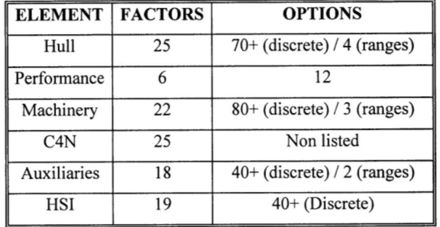
Table 2 details the number of factors and options for each element.
Table 2: Initial Element/Factor/Option Summary for SSC
Once the trade spaces were established, analysis efforts focused on the application of SBD principles to reduce the trade spaces. However, each reduction required
substantiation and for this, each SEM conducted trade studies to develop and
comparatively evaluate subsystem alternatives within the element trade space. SEMs also developed evaluation criteria to support the comparative evaluation of the subsystem alternatives. SSC measures were defined in an evolutionary manner3 to assist in the comparative evaluation of integrated concepts.
The SEMs conducted element-specific analyses to screen the trade spaces of infeasible or dominated options and develop a set of non-dominated attribute ranges, leaving the still
' Evolutionary refers to the manner in which the metrics used for ultimate concept scoring were derived in
part using the factor and option attributes. Thus, if a factor was screened and its attributes no longer relevant at the whole craft level, that measure would be removed.
30
ELEMENT FACTORS OPTIONS
Hull 25 70+ (discrete) / 4 (ranges)
Performance 6 12
Machinery 22 80+ (discrete) / 3 (ranges)
C4N 25 Non listed
Auxiliaries 18 40+ (discrete) / 2 (ranges)
feasible regions of the trade space on the table. The Design Integration Team (DIT, made up personnel ranging from the SDM through the DIM) facilitated the trade space
reduction efforts with constant and proactive oversight. Involvement of the Technical Warrant Holders (TWHs)4 was fundamental to the SSC implementation of SBD. They were involved from the start, from the initial setup of the element trade spaces to the concurrence of SBD results.
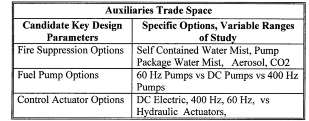
The reduction effort culminated in reduced trade space summaries like that shown in Table 3. Starting from 18 factors and 40+ options, the Auxiliary trade space was reduced to 3 factors and 11 options.
Auxiliaries Trade Space
Candidate Key Design Specific Options, Variable Ranges
Parameters of Study
Fire Suppression Options Self Contained Water Mist, Pump Package Water Mist, Aerosol, C02 Fuel Pump Options 60 Hz Pumps vs DC Pumps vs 400 Hz
Pumps
Control Actuator Options DC Electric, 400 Hz, 60 Hz, vs
Hydraulic Actuators,
Table 3: Reduced Auxiliary Trade Space Summary
The number of possible combinations for the Auxiliary trade space was 48. Although still quite large, this was a significant reduction from the initial thousands of
combinations for this element alone. This table also does not show possible dominated combinations (inter/intra element) that would provide further reduction. Similar reduction efforts were conducted on all the elements with a summary of the results contained in Table 4.
4 Technical Warrant Holders are individuals holding Technical Authority (TA) for a given technical area.
The TWH is accountable for establishing, maintaining, and interpreting technical standards, tools, and processes including certification requirements for the design and life cycle engineering of Navy ships and systems. Upon identifying the appropriate TWHs for the SSC effort, the SEMs kept the appropriate TWHs briefed on events and progress in the SBD effort, soliciting their inputs as warranted.
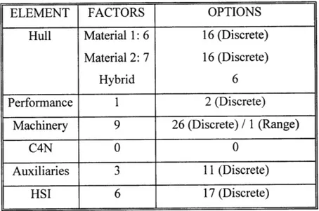
Table 4: Reduced Element/Factors/Options Summary for SSC
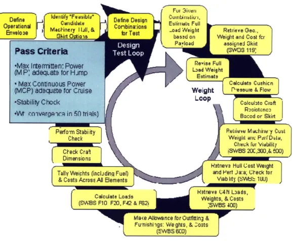
Efforts for further reduction continued until allotted project time required the DIT to move to developing integrated (craft level) concepts for comparative evaluation. These were constructed based on combinations of non-dominated candidate systems solutions that were developed by looking across the elements and then subjected to a balancing loop to ensure that the design candidates passed a first order test for platform viability. The number of concepts that entered the balance loop numbered just over 10,000. Figure 8 shows a diagram of the balance loop process used by the SSC.
ELEMENT FACTORS OPTIONS
Hull Material 1: 6 16 (Discrete) Material 2: 7 16 (Discrete)
Hybrid 6
Performance 1 2 (Discrete)
Machinery 9 26 (Discrete) / 1 (Range)
C4N 0 0
Auxiliaries 3 11 (Discrete)
' Max ContDnuous Pooer the S BleoP s
(Mc P) adsuete for Cruise mint terure a w
-Stability Chock a maues rut
f
W
mArigca in 50 tri tolc) truht orkn(Tp cally Weights a wa Fnally
C
Baselcte forWeightk rur & Falow DimeRsiintenc0
Rlliev MullChin-yeiuht
Tally Weihts (incl diWgight an PerfD- e l & Cots cros ADElemntsViablhty (SVWd'-- 1WU)
Hetneve (;4N LOads, Calcuate
o IsWeights, & Costs
(SWBS8 F1 0 F20, F4& FB2) 'SWBS 400)
Ma<e Allowance for Outfittin!] & .Fu'nishi'igs: We ghts, & ~;osts
(EWBS 6CO)
Figure 8: Diagram of the SSC Balance Loop Process
The deep yellow blocks, the first three blocks in Figure 8, describe the initialization steps in the Balance Loop. A few craft level operational envelope parameters are established such as assumed payloads and required cruise speed, ambient temperature, and wave height. In addition, parameters describing the sets of non-dominated options remaining for each of the elements are defined so that the total possible combinations remaining may be exhaustively tested in the Balance Loop.
Candidate designs that made it through the balancing loop were comparatively evaluated using a multi-attribute utility model: (1) defined by the craft-level measures resulting from the metric development effort that took place throughout the PPD work; and (2) developed specifically for this purpose using commercially available software. Finally, an SSC Baseline Design was selected for further analysis in PD.
3.4 SBD Hurdles
Being the first instance of the use of SBD in the naval ship design community, significant engineering hurdles were faced by the SSC Program. Combining the organizational structure of naval design with that optimal for SBD was not completely possible due to the timing of instituting SBD in the project. The design was also constrained on selection of options in some elements. Considering SBD design is about enhancing design
flexibility through design space exploration and delayed design making, the extent to which these decisions limit the work was unclear.
Cultural hurdles were also faced as in general, engineers are very solution oriented, trying to get to solutions as efficiently as possible. Given a problem, they are excellent at detailed designed solutions; however, a SBD approach shifts away from this line of thinking. The focus turns from deriving a specific solution to looking at a host of design variables and options that could accomplish the required task. It becomes paramount to
substantiate why an option will not work rather than why it might work, especially early on. This lies at the core of how SBD design practice achieves greater design flexibility.
3.5 Design Process Results
The design effort in the SSC project began with greater than 115 design parameters with an almost uncountable number of option combinations. This was reduced to a design space of 11 key factors (design parameters) and slightly less than 3400 design
combinations (those remaining after the balance loop) that were comparatively scored at the craft level. From these design combinations, a preferred concept was selected with backup options for key components in the identified 11 key parameters. These key parameters along with the trade space reduction summary are contained in Figure 9.
Trade Space Redn Design Prameter
(Progressafrom 05/07108 to PD 1) Design Parameter________
140 50 Hull Material
12o Hull Depth
40
10- Transverse Bulkhead Spacing
3 t # of Longitudinal Bulkheads
o Skirt Type
6 -0
Machinery Architecture M~ 40-&
-10 Propulsor Duct Diameter
Electrical System Architecture
0-0
5i5n 51/200 SM 5 S11228 -200 820 71mMO 0 7/24008 8/7/008 821,2008 /4W8 0 Electrical Service Frequency
=Vi Parameters -- #of options (Log 10) EPLA Electric Load
Figure 9: Trade Space Reduction Summary along with key Design Parameters
The design effort revealed a lot in regards to requirements and decision traceability. In particular, the evolution of requirements throughout the process needed to be
accommodated by the evolutionary reduction of the trade space to adequately capture and reflect changes. Since each element began with a list of initial (draft) requirements, the changes made had to be balanced with the reduction of options and the learning that
occurred (in regards to various options) that leads to design discovery. Simply stated, new requirements were discovered and included due to design factor exploration.
Traceability lies at the foundation of SBD as it provides for future design flexibility and allows for delayed decision making. It also allows tracking of which decisions are made
by the SEMs and which need to be approved at a higher level of authority. This is
important as with the large number of decision and design space reduction required, having to have all decisions approved by too high of an authority would have hindered any progress. Conversely, some decisions involve key design issues and as such, need extra visibility.
3.6 SBD success
Being the first use of SBD in U.S. Navy ship design, the program identified early in the effort four ways in which to measure the SBD success. These are presented in order of increasing impact to the initial design and are based on the thoroughness of the result.
"'? ?? ... ... ... ... ....
e Did the SBD effort produce a truly unique solution? This was not achieved; however, the reason can be found in the constraints placed on the process. One particularly limiting constraint was precluding the use of any technology not already
demonstrated in a similar operational environment. Thus, any combinations of chosen options would be unique in the sense that those chosen options may have never been combined before at the integrated level; however, on a component level, it contains mature technology and thus uniqueness was not necessarily achievable. Such constraints limit innovation at the sake of reducing risk.
* Did the SBD effort provide a thorough canvass of the design space, with a sound body of analysis substantiating the tradeoffs available? This was achieved and the only debatable issue is the thoroughness of the effort. Determination in this regard may only happen at a later time when requirements are changed.
e Did the SBD effort identify those design parameters of greatest impact to a good design and which options or ranges of these parameters are of greatest value to a good craft? As previously stated, the 11 most important design parameters were
determined along with the ones of greatest.
* Did the SBD effort provide a staged progression towards a globally optimal design, with each stage resolving design details with successively greater fidelity? This was not achieved and further SBD work is required to understand how to achieve this outcome.
Overall, true judgment of the SBD effort will only come later on as the program progresses through the acquisition process where requirement changes experienced during subsequent phases allow the design team to leverage the body of data and analysis that remains.
The question then arises whether a point based design approach would have provided the same results. There is a chance that the same design could have been created; however,
the question then reverses to what would happen to this design in the face of future
requirement changes. Point based approaches are not geared to handle changes late in the design process. Doing so requires tradeoffs that may result in a design that is less than optimal. The ability to identify the most important design parameters would also be in question as the construction of the design space in a SBD application facilitates the evaluation of design parameters where the point based approach does not.
4.0 Defining the SBD Framework
The SSC program provided an overview of their PPD effort that utilized SBD principles; however, this chapter seeks to define a general framework for SBD implementation that can be applied to the broader scope of naval design projects. This framework provides the basis for undertaking the submarine concept design presented in the next chapter.
4.1 Framework Summary
Although the use of SBD design was initiated in the SSC project as part of the PPD process, Figure 10 provides a generic model that illustrates the major steps in the SBD process.
Process Map (4.3)
FgTrade Space
Summary at the Element Element with Specif ic(4.4) Exclusions
(4.5.1) for Balancing Balancing
Trade Space Dominated/ Itgat inedto Inr-E
M nter-eement Combintin Configurations ElementsntReucio
Figure 10: SBD Framework Model
The shape of the figure illustrates the narrowing of the design space until a preferred concept or family of concepts is selected. The remainder of this chapter discusses how this framework is implemented with examples provided from the SSC example
highlighting how they accomplished certain aspects.
4.2 Organizational Structure
Prior to beginning exploration in the trade space, there is a certain amount of set up work required. As in any process, proper preparation and role definition is imperative for the proper functioning of the SBD effort and developing an organizational structure that
operates in conjunction with the SBD effort is vital to ensuring success. At the same time, if early on in the acquisition process there is a clear understanding that SBD is to be used, a SBD decomposition that matches future organization breakdown can be more easily created.
Specifically, the IPPD approach used in the VA submarine class along with the successes achieved through its use provide a good idea of how future submarine development will proceed. In the event that SBD is to be used in concept exploration or PPD, the goal of team organization should be to match the structure that will be used for later design processes. Key elements of IPPD approach where an SBD effort can takes its
organizational structure from include the Functional Area Teams and System Integrations Teams. The teams operate concurrently with the modular breakdown of the design as shown in the figure below.
SEna"RoomRaftgj] 2BJ5*Super edule'(2BL NGi
Stem EngeRoomMIosl QSM" Bw LNGNN) I
AMRMOdule Habdabity Module Weapons module
Figure 11: Virginia Class Design Modules
(image found at ussnewmexico.net)
In environments where the IPPD will not be employed, organizational breakdown should still follow that which will be used in design and construction.
4.3 Process Map
Once an organizational structure is defined and understood, the next major requirement is the development of an executable process. Development of such a process requires accommodating multiple document requirements and directives (e.g. Navy Systems Engineering Guide, Ship Design Manual). Process development requires defining and deriving the key decisions and determining the flow of information throughout the process. Once completed, the process can assist the program in detailed planning of the technical effort, resolve dependencies, and assist in modifying the process to meet all program requirements. This work should lead to a full process map that directs the entirety of design process.
The use of DOSE facilitated the SSC programs development of an executable program; however, any tool that allows the design team to develop a process that takes into account all required inputs, outputs, value flow, information flow, and stakeholders needs can be used. The process itself is used to communicate how the overall SBD effort moves from a collection of element/factors/options/variables to ship level concepts. Model based software is another tool that can be used to illustrate this flow. Appendix A contains the SSC program process map. The final process should guide the SBD effort from element creation to a final preferred concept.
4.4 Set Development
With an organizational structure in place and a process defined to apply SBD principles, the next step is to describe the trade space so that the SBD process can be implemented. An initial consensus compilation of operational requirements is developed to begin the set-based activity. This compilation goes beyond notional requirements and looks at the operational environment. This will result in a mix of hard and soft constraints,
capabilities asked for by the customer or other stakeholders, and capabilities required of similar craft in similar operational environments.
Requirements in general are evolving as some will not change throughout the design effort, some will change with TWH input, and others will change based on stakeholder
direction. Additionally, others will change based on the need to satisfy conflicting requirements. Lastly, new requirements will emerge as the design progresses and there is a better understanding of the details of the design. This evolution and maturation process drives changes to the requirements documents. Thus, the initial compilation used to initiate the set-based design is meant only to get the SBD effort started.
With the compiled set of operational requirements, a list of options, attributes, and attribute ranges necessary to characterize the ship at the platform level and satisfy requirements, is developed.
4.4.1 Element Definition and Variable/Range Selection
The initial exploration of the trade space yields results that serve as inputs into the chosen element breakdown. The development of factors is derived from the exploration of how the notional requirements (and operational requirements) can be met. Although some
factors are naturally part of the design and do not necessarily map to a specific
requirement, others will have direct ties. With a list of initial factors or elements defined, the effort then moves to selection of elements to represent a set of factors. The selection
of elements should model the product architecture.
Chosen attributes and ranges serve only as points of the departure; each Element Manager (EM)5 is free to relax any of the ranges based on their knowledge of the available design issues and available technologies. The ideal implementation requires any relaxation assumptions made by the EMs to be subject to review by someone, as defined in the organization structure and mapped by the design process, with oversight responsibility for the total design space.
This part of the process must ensure that the trade space summary reflect the EM's best judgments regarding the factors and options to be examined with a detailed plan for their
study completed. Also, there must be a sound reason for the inclusion of each factor and option (e.g. the factor has not been eliminated as a potential vital factor at the craft level.)
5 An EM as defined here would be synonymous with the role of the SEM in the SSC project.
The factor or option in question should not be included if it does not impact the design enough to be considered within the SBD process. Also, where there is a tight schedule and no time for basic science inquiry, the technology needs to be understood. If the EM does not understand the factor well enough to measure it, or can not anticipate how it might impact their design, the factor does not warrant a place in the trade space.
4.5 Narrowing the Set Trade Space
The trade space reduction effort seeks to screen the trade spaces of infeasible or
dominated options and develop a set of non-dominated attribute ranges. This leaves the still feasible regions of the trade space on the table. The trade space reduction efforts can be described as two sub-efforts: (1) Factor/Option Screening (4.5.1), and (2) Combination Screening (4.5.2). The Factor/Option Screening effort focuses on screening whole design parameters and options or option sets, while the Combination Screening effort focuses on screening specific combinations of options based on incompatibilities.
The trade space reduction effort requires constant oversight as the necessity to reduce initially large sets of data must be balanced by the need to not exclude reasonable, and potentially optimal, solutions. Frequent meetings by EM's can usher the process along and provide the necessary push for continued progress.
Of all activities involved in the SBD effort, trade space reduction is the most challenging and stressful. Considerable time and resources in this part should be allocated for full exploration of options and combinations. Proper documentation is paramount throughout the process as the studies conducted and decisions made create the data store where future design efforts and flexibility are derived.
4.5.1 Element Specific Exclusion
The ability to narrow the element trade space focuses on a factor (design parameter) / option (variable range) screening process where the reduction effort is tracked in trade space summaries. The following represent the screening rules used in the reduction effort: