Development and Simulation of a Cylindrical
Cusped-Field Thruster and a Diagnostics Tool for
Plasma-Materials Interactions
by
Anthony Pang
B.E., Mechanical Engineering, The City College of the City University
of New York (2011)
Submitted to the Department of Aeronautics and Astronautics
in partial fulfillment of the requirements for the degree of
T7
Master of Science in Aeronautics and Astronautics
at the
MASSACHUSETTS INSTITUTE OF TECHNOLOGY
ARCHIVES
ssCHUSETTS INSIfUTE
O ECHNOLOGy
L1BRARIES
June 2013
@
Massachusetts Institute of Technology 2013. All rights reserved.
Author ...
-. ..
.
...
...
Department of Aeronautics and Astronautics
23 May 2013
C ertified by ... X
... V...
Manuel Martinez-Sanchez
Professor of Aeronautics and Astronautics
/
r
Thesis Supervisor
A ccepted by ...
...
Eytan H. Modiano
Professor of Aeronautics and Astronautics
Chair, Graduate Program Committee
Development and Simulation of a Cylindrical Cusped-Field
Thruster and a Diagnostics Tool for Plasma-Materials
Interactions
by
Anthony Pang
Submitted to the Department of Aeronautics and Astronautics on 23 May 2013, in partial fulfillment of the
requirements for the degree of
Master of Science in Aeronautics and Astronautics
Abstract
A low power, Hall-effect type plasma thruster known as the MIT-Cylindrical
Cusped-Field Thruster (MIT-CCFT) has been developed and simulated using a fully-kinetic plasma model, the Plasma Thruster particle-in-cell (PTpic) model. Similar to the Diverging Cusped-Field Thruster (DCFT) previously developed in the Massachusetts Institute of Technology Space Propulsion Laboratory, this thruster uses cusped mag-netic fields aligned in alternating polarity in order to confine electrons, thus slowing their flow to the anode and readily ionizing neutral gas, which is then electrostatically accelerated by the anode. The design methodology for the CCFT will be discussed, with significant emphasis on the effects of magnetic topology on thruster performance. In particular, while the topology is similar to that of the DCFT in that it also confines the discharge plasma away from the channel walls to limit wall erosion, the CCFT was also designed to minimize plume divergence.
To predict the CCFTs performance and plasma dynamics, the design has been modeled and simulated with PTpic. From multiple simulations of the CCFT under different operating conditions, the thruster performance and plume characteristics were found and compared to past simulations of the DCFT. Specifically, the predicted nominal total efficiency ranged from 25 to 35 percent, providing 4-9 mN of thrust at a fixed xenon mass flow rate of 4.0 sccm, whilst consuming 90-400 W of power and with a corresponding nominal specific impulse of 1050 to 1800 s. Preliminary observations of the particle moments suggest that the magnetic confinement of the plasma isolates erosion of the channel walls of the discharge chamber to the ring cusps locations. In addition, in contrast to the DCFT, the CCFT does not have a hollow conic plume; instead, its beam profile is similar to that of traditional Hall-effect thrusters.
To supplement the efforts for optimizing longevity of the cusped-field thruster, a new diagnostic tool for erosion studies, novel to the electric propulsion community, has been implemented and has undergone preliminary validation. Ion beam analysis (IBA) allows for in-situ measurements of both composition and profile of the surfaces
of the discharge region of a plasma thruster during operation. The technique has been independently tested on individual coupons with the use of the Cambridge Laboratory for Accelerator Study of Surfaces (CLASS) tandem ion accelerator. The coupons, which are composed of materials with known sputtering rates and/or are commonly used as insulator material, are exposed to helicon-generated plasma to simulate the sputtering/re-deposition found in thruster discharge region. Through comparison of ion beam analysis traces taken before and after plasma exposure, the effective erosion rates were found and validated against simulated results.
Thesis Supervisor: Manuel Martinez-Sanchez Title: Professor of Aeronautics and Astronautics
Acknowledgments
Logistically, this work was supported by the National Science Foundation through the
NSF Graduate Research Fellowship Program and by the Air Force Office of Scientific
Research.
However, even with fiscal support, the work presented in this thesis could not have been possible without significant contributions from countless colleagues, ad-visers, and friends. First, I want to thank Professor Martinez-Sanchez for offering me this challenging and exciting opportunity, and the leeway to pursue it. Without his mentorship and support, this academic adventure could have easily ended up a misadventure. I would also like to thank Professor Lozano for, among many other things, being one of the best instructors, in the lab and in the classroom, that I've ever had.
Other significant contributors to the successful completion of this thesis and the fruition of the CCFT include: Stephen Gildea, for teaching me everything I know about PTpic; Taylor Matlock, for giving me much of the inspiration and motivation for building the CCFT and teaching me everything I know about plasma thruster experimentation; Regina Sullivan, for giving me a crash-course on ion beam analysis, teaching me how to operate a particle accelerator in a week, and generally making Chapter 5 possible; Todd Billings, the MIT Aero/Astro technical instructor, and my UROPs, Dennis Prieto and William Waste, for helping me build the CCFT; and my primary Astrovac lab partners, Louis Boulanger and Jaume Caville, who help me convert a hunk of metal in the vacuum chamber into an operating cusped-field thruster.
I would also like to thank all of my friends and colleagues in the SPL. I drove
you all crazy but you still gave me thoughtful discussions on space propulsion and you all showed up at the pig roast. Special thanks to: Louis and Carla, who had to put up with having me as an officemate for the last two years; Steve and Louis (again!), for valiantly trying to keep me fit twice a week; Fernando, for helping me remember Electric Circuits 101 at least one a week in the lab; and Tom, for always
taking the time to answer all of my questions about the cluster and troubleshooting my computer/coding problems.
I would also like to thank my friends, GA3 execs, and roommates for making my time in Cambridge memorable. In particular, I want to acknowledge Patrick, Simon, Wei, Hang, Jay, Luis, Pedro, and Dan Rothenberg, who kept me sane. There simply weren't enough Settler of Catan games, trivia games, Pirates of the Charles events, or IHOP trips but we'll remedy that someday.
Last, but not least, I dedicate the thesis to my loving parents, my grandparents, sister Xin, and brother-in-law Brandon. I've been blessed with a family who taught me the value of education and have never wavered in supporting me, no matter where my dreams take me.
Contents
1 Introduction
1.1 Hall-effect Thrusters . . . . 1.2 Plasma-Surface Interactions and Thruster Longevity . . . 1.3 Research Overview . . . .
2 The MIT Cylindrical Cusped-Field Thruster Overview 2.1 Background: Cusped-Field Thrusters . . . .
2.2 The Diverging Cusped-Field Thruster . . . . 2.2.1 DCFT Drawbacks . . . . 2.3 Cylindrical Cusped-Field Thruster Basic Design and App
2.3.1 Flat Exit Separatrix and Beam Divergence . . . . 2.3.2 Magnetic Source Selection . . . . 2.3.3 Simulated CCFT Magnetic Field . . . . 2.4 CCFT Thruster Design . . . . 2.4.1 Dielectric Insulator Channel . . . . 2.4.2 Anode Design and Propellant Inlet . . . . 2.5 A ssem bly . . . .
2.6 Magnetic Field Measurements . . . .
roach
3 CCFT Preliminary Results and Performance
3.1 Experimental Setup . . . .
3.2 Experimental Facility and Equipment . . . . .
3.2.1 Astrovac . . . .
19
20 21 24 25 25 28 30 31 32 34 34 35 36 37 39 4143
43 44 44. . . .
. . . .
. . . .
3.2.2 Cathode . . . . 44
3.2.3 Power Supplies . . . . 46
3.2.4 Flow Controllers . . . . 46
3.3 Preliminary Results from First Discharge and Stable Operation . . . 46
3.3.1 Visual Observations of the Plume . . . . 46
3.3.2 Anode Voltage and Flow Scans . . . . 49
3.3.3 Anode Current . . . . 49
3.3.4 Floating Body Potential . . . . 52
4 CCFT Numerical Simulations, Preliminary Results and Performance
Characterization
53
4.1 Background: Fully Kinetic Modeling and Plasma Thruster Particle-in-C ell (PT pic) . . . . 534.1.1 Particle-in-Cell Modeling of Plasmas . . . . 53
4.1.2 Plasma Thruster Particle-in-Cell (PTpic) . . . . 56
4.2 Boundary Conditions, Grid Generation, and Simulation Inputs . . . . 58
4.2.1 Magnetic Field and Grid Generation . . . . 58
4.2.2 Boundary Conditions . . . . 59
4.2.3 Simulation Parameters . . . . 62
4.3 Preliminary Simulation Results . . . . 62
4.3.1 Plasma Structure . . . . 65
4.3.2 Performance Characterization . . . . 65
4.3.3 Erosion Estimates . . . . 71
4.4 Simulations and Preliminary Experimental Observations . . . . 74
5 Ion Beam Diagnostics for Erosion Measurements
77
5.1 Background . . . . 775.2 Rutherford Backscattering Spectrometry and Nuclear Reaction Analysis 79 5.3 Simulation Software and Depth Maikers . . . . 80
5.3.1 SIM NRA . . . . 80
5.4 Research Overview . . . .
5.5 Validation Procedure . . . . 5.5.1 Calibration and Gaussian Fitting . . . . 5.5.2 Validation with SRIM Estimates . . . . 5.6 Experimental Facilities: Plasma Surface Interactions Surface Center . 5.6.1 Cambridge Laboratory for Accelerator Study of Surfaces (CLASS) 5.6.2 Setup of Diagnostics Equipment . . . . 5.6.3 Helicon Plasma Erosion . . . . 5.7 Preliminary Results Summary . . . . 5.7.1 Interpretation and Discussion of Results . . . . 5.7.2 Effects of Heating . . . .
6 Conclusions and Future Work
6.1 CCFT Thruster Recommended Studies . . . . . 6.1.1 Continued Numerical Simulations . . . . 6.2 Ion Bean Diagnostics Recommended Studies . .
6.2.1 External Validation Studies . . . .
6.2.2 Validation with the DCFT . . . .
99
. . . . 100 . . . . 103 . . . . 104 . . . . 104 . . . . 105A Cylindrical Cusped-Field Thruster SolidWorks Drawings
B Instructions for CLASS Tandem Accelerator Operations
B.1 Accelerator Start-up Procedure . . . . B.2 Sputter Source Start-up Procedure . . . .
B.3 Beam Extraction Procedure . . . .
83 84 85 86 87 88 91 93 95 95 97
111
123 123 124 124List of Figures
1-1 Hall-effect Thruster Schematic . . . . 21
1-2 Sputtering Schematic (left), Visual Display of Insulator Cone of the Diverging Cusped-Field Thruster, before and after erosion (right). . . 23 2-1 Magnetic mirroring of electrons in a cusped-magnetic field. Note the
incident ion attracted to the cusp, where there is a sheath from the electron flux on the wall. . . . . 26
2-2 Schematic of the Princeton Cylindrical Hall Thruster (top), CHT mag-netic circuit and field lines (bottom). . . . . 27
2-3 Schematic of the Thales HEMPT magnetic circuit and potential plot
(left), HEMPT plasma plume (right). . . . . 27 2-4 Cross-sectional schematic of the diverging cusped-field thruster, with
overlayed magnetic field lines. . . . . 28 2-5 Erosion profile of DCFT Insulator Cone after 204 hr longevity
experi-ment performed at the AFRL. . . . . 29
2-6 Hollow conical plume of the DCFT operating in high current mode (left), Plume of the DCFT operating in low current mode (right). . . 31 2-7 Magnetic topology, field lines and field strength of the DCFT, with the
convex sepatrices noted. . . . . 32
2-8 External electromagnet placed at end of DCFT (left), Simulated effect on separatrix from increased magnet current (right). . . . . 33
2-9 Plasma plume profile without applied electromagnet (left), Plasma plume profile with electromagnet (right). . . . . 33
2-10 Magnetic field topology represented by magnetic flux lines within the
cylindrical cusped-field thruster, in vacuum. . . . . 35
2-11 Simulated magnetic field strength within the CCFT, in vacuum. . . . 36
2-12 CAD cross section and bill of materials for the CCFT. . . . . 37
2-13 Boron nitride insulator components (left), Boron nitride insulator, in thruster configuration (right). . . . . 38
2-14 Cross section of the anode, with insulating sheath in the steel base. . 38 2-15 DCFT insulator prior to firing (left), DCFT insulator after firing (cen-ter), Eroded diffuser disk (right). . . . . 39
2-16 Schematics of assembly system for the CCFT. . . . . 40
2-17 CCFT fully assembled, with Busek hollow cathode (left), CCFT in Astrovac with cathode on stage system (right). . . . . 41
2-18 Simulated and measured radial magnetic field along boron nitride in-sulator . . . . . 42
3-1 Sketch of the schematic of the experimental setup for the CCFT used at SPL. ... ... 44
3-2 The Space Propulsion Laboratory Astrovac vacuum chamber. The chamber, used for the CCFT testing, is pumped by two cryopumps and one mechanical roughing pump. . . . . 45
3-3 Busek BHC-1500 hollow cathode. . . . . 45
3-4 The CCFT firing with 4 sccm Xe flow and 100 V at the anode (left), CCFT firing with 4 sccm Xe flow and 200 V at the anode (right). . . 47
3-5 Endcap of the CCFT coated with Kapton tape. . . . . 47
3-6 The CCFT firing with 4 sccm Xe flow and 200 V at the anode. ... 48
3-7 The CCFT firing with 4 sccm Xe flow and 300 V at the anode. ... 48
3-8 Anode voltage scan, with different keeper conditions. . . . . 49
3-9 Anode flow scan. . . . . 50
3-10 Anode power levels. . . . . 50
3-12 Shattered remains of the diffuser disk from thermal expansion (left),
Sheared off graphite tip from anode stem (right). . . . . 51
4-1 Particle-in-cell flow chart. . . . . 54
4-2 Interpolated Magnetic Field Lines and Strength Inputs for the CCFT sim ulation. . . . . 59
4-3 Cylindrical Cusped-Field Thruster mesh with thruster components iden-tified . . . . 60
4-4 Note the high negative floating body potential in (a), which does not get resolved, completely alters the trajectories of the charged super-particles, and eventually leads to the code to crash. . . . . 61
4-5 Ion and electron population, over 20 ps, operating at 4 sccm Xe and 600V. Note that the difference between electron and ion count is ac-counted by the presence of double ions. . . . . 63
4-6 Neutral population, over 20 ps, operating at 4 scem Xe and 600V. . 64 4-7 Anode current, over 20 ps, operating at 4 sccm Xe and 600V. .... 64
4-8 Streamlines and ion densities for the DCFT and CCFT. Note how the streamlines follow a hollow conical plume of the DCFT whereas the CCFT has a solid plume shape. . . . . 66
4-9 Radial density of the CCFT Plume, 5 centimeters and 7 centimeters from the thruster exit. Note that the density drops drastically 1 cen-timer away from the centerline. . . . . 67
4-10 Single ion superparticle density snapshot moment at 20 ps. . . . . 68
4-11 Electron superparticle density snapshot moment at 20 ps. . . . . 68
4-12 Single ion temperature snapshot moment at 20 ps. . . . . 68
4-13 Electron temperature snapshot moment at 20 ps. . . . . 69
4-14 Potential snapshot moment at 20 ps. . . . . 69
4-15 Thrust, anode current, and beam current for the CCFT operating at 250 V anode potential and injection of 4 sccm Xe . . . . 70
4-16 Thrust, anode current, and beam current for the CCFT operating at
600 V anode potential and injection of 4 seem Xe . . . . 72
4-17 Erosion rate of the CCFT, operating at 250 V and 4 seem Xe. .... 73
4-18 Erosion rate of the CCFT, operating at 600 V and 4 seem Xe. .... 74 4-19 Simulation of CCFT, operating at 250 V at the anode and with 4 seem
Xe flow (left), CCFT operating at 250 V at the anode and with 4 seem X e flow (right). . . . . 75
4-20 Angled image of boron nitride insert in the CCFT, with rings of erosion at the cusps and deposition in between. . . . . 75 5-1 Schematics illustrating how profilometry measurements were performed
for the 204 hr longevity test. . . . . 78 5-2 Schematic of Rutherford Backscattering Spectrometry and Nuclear
Re-action A nalysis. . . . . 81 5-3 Simulated Rutherford Backscattering Spectroscopy and NRA spectra
of a lithium implanted aluminum sample. . . . . 81
5-4 Simulated spectra of implanted Li, at various depths. . . . . 82 5-5 Setup for planned ion beam analysis erosion/redeposition experiments
with the DCFT. . . . . 84
5-6 Procedure for ion beam analysis. . . . . 85 5-7 Cambridge Laboratory for Accelerator Study of Surfaces (CLASS) 1.7
MV tandem ion accelerator. . . . . 88 5-8 CLASS accelerator schematic, with highlights on cesium ion sputtering
source... ... 89 5-9 Diagram of the electrostatic Einzel lens, which focuses on negative ions
from the cesium source . . . . 89 5-10 CLASS accelerator schematic. . . . . 91 5-11 Setup configuration for NRA and RBS detectors and respective spectra. 92 5-12 DIONISOS helicon-generated plasma eroding a sample. . . . . 93 5-13 NRA trace of aluminum coupons UE1,
E
1, and E2 . . . . .95
5-14 NRA trace of aluminum coupon before and after being heated to 300'
C for 30 m inutes. . . . . 97
6-1 Basic schematic of the Faraday probe used in the experiments. . . . . 100
6-2 Basic schematic of the Retarding Potential Analyzer used in the
ex-perim ents. . . . 102
6-3 Milli-Newton Thrust Stand (left), Setup of DCFT/MiNTS and cali-bration equipment in Astrovac (right). . . . 103 6-4 Front view of experimental setup (left), Back view of the experimental
List of Tables
1.1 Lifetimes of Commercial Hall-effect Thrusters . . . . 22
2.1 Measured Radial Magnetic Field Strength . . . . 42
3.1 BHT-200 Anode Current Measurements . . . . 52
4.1 Variables Used for Simulation . . . . 62
4.2 Performance Characteristics for Various Operating Conditions of the CCFT ... .. ... 71
5.1 SRIM Simulated Sputter Yield, Ar Plasma on Al . . . . 86
5.2 Expected Erosion Depths . . . . 87
5.3 Energy Shift from Experiment and Erosion Determination . . . . 96
Chapter 1
Introduction
In-space propulsion has traditionally been dichotomized into broad categories: chem-ical propulsion and electric propulsion. Generally, these two types of propulsion have been utilized in distinct theaters of space missions. Through harvesting the chemical energy of its propellants and at the cost of specific impulse, chemical thrusters are able to create high enough levels of thrust (newton to kilo-newton) to perform mis-sions which necessitate fast orbit and plane changes, and rapid orbital maneuvers. However, the lower specific impulse of these devices results in higher propellant mass, which could add significant costs to the mission.
Electric propulsion devices generate thrust via the use of electric energy to accel-erate the propellant. In contrast, while most electric propulsion devices are generally incapable of generating thrusts exceeding 1 N, they possess specific impulses signifi-cantly higher than those found in chemical propulsion (thousands of seconds, opposed to the low hundreds found in typical chemical devices such as monopropellants, bipro-pellants, and cold-gas thrusters). Specific impulse can be defined as the relationship between thrust and the amount of propellant used per unit time, and represented in the following equation:
IS = (1.1)
is the mass flow rate of the propellant. From this ratio, it is apparent that high specific impulse results in relatively high thrust obtained with low fuel consumption. Currently, there are many missions, such as deep space missions and long-term drag cancellation for geostationary satellites, which require high specific impulse (> 1000 seconds) due to a high AV requirement for their long duration. In addition, for missions without time constraints, electric propulsion can be used to perform station-keeping for remote sensing or telecommunication satellites, slow orbital maneuvering, plane changing, and orbit raising [3].
1.1
Hall-effect Thrusters
Hall-effect thrusters, which were first developed in the Soviet Union in the early 1960's, consist of a cathode-anode pairing where electrons traveling from the exter-nally mounted cathode to the high potential anode are impeded by a radial magnetic field. The magnetic field, applied with electromagnetic coils, is strong enough (0[100 Gauss]) to trap the electrons within their gyroradii. Electrons also experience an
E x B drift, which creates a Hall current:
JHall
= ene B2 (1'2)These electrons drift azimuthally and, through collisions with injected neutral propellant, create ions, which are electrostatically accelerated out of the chamber and neutralized by other electrons emitted from the cathode. Though Hall thrusters are electrostatic accelerators, the reaction force felt by the structure is not electrostatic but magnetic, through the Hall current. A schematic of a Hall-effect thruster can be
seen in Figure 1-1.
The ions are electrostatically accelerated to an exit velocity,
2e#
vi = - (1.3)
where
#
is the potential at the location of ionization. This is the cause of theElectromagnet V Cathode -n Bd electrons XeonAnodeE Dielectric Z Walls CL Figure 1-1: Hall-effect Thruster Schematic.
higher thrust density Hall thrusters have compared to ion engines, as Hall thrusters are not space-charge limited given the quasineutrality of the plasma in the discharge region. As a result of their higher thrust density and the high reliability (100% success rate in over 200 missions in orbit), Hall thrusters are now increasingly studied and adapted by industry for in-space propulsion. The emphasis of the current research has been devoted toward improving thruster efficiency and extending the lifetime of the devices. Toward those ends, improvements and modifications to low power Hall thruster designs in recent years have included incorporation of high power permanent magnets and adaptation of cusped magnetic topology. The adaptation of these tech-niques at the Massachusetts Institute of Technology has led to the development of the Diverging Cusped-Field Thruster [1] and, with continuing refinement, the Cylindrical Cusped-Field Thruster. The effects of these modifications and their incorporation into the Cylindrical Cusped-Field Thruster design will be discussed in detail in the following chapter.
1.2
Plasma-Surface Interactions and Thruster Longevity
Unfortunately, in addition to propellant capacity, the longevity of any mission using electric propulsion is also limited to the lifetime of these devices. In particular, plasma
sputtering of the dielectric chamber walls of the discharge region of plasma thrusters is a primary life-limiting mechanism for long term satellite station-keeping and long-range space exploration. For Hall-effect thrusters in particular, failure can be defined as soft failure, which is when the dielectric insulator has been eroded to the magnetic circuit and would eventually lead to damage to the electromagnetic coils and thus results in thruster inoperation.
Table 1.1 [7] shows that soft failure severely limits thruster applicability for long missions, rather than the predicted lifetime. In order to address this issue, the primary source of erosion which causes the soft failure, particle sputtering from the plasma, must be investigated.
Table 1.1: Lifetimes of Commercial Hall-effect Thrusters
Thruster
Anode
Anode
Soft-Failure
Predicted
Designation
Power [W]
Efficiency
Time [h]
Lifetime [h]
SPT-50
320
47 %
>2,500
-KM-45 310 40-50% 3,500-4,000 -KM-32 200 30-40% 2,000-3,000 3,000 BHT-200 200 43.5% 1,287-1,519 >1,700HT-100
175
25%
300
1,500
SPT-30
150
26%
600
-SPT-20M <100 <38% 594-910 4,000
In particular, the sputtering of boron nitride (BN) is an especially critical topic due to its widespread use as as insulator wall material in Stationary Plasma Thruster
(SPT) type Hall thrusters. Furthermore, deposition of the sputtered BN can
contam-inate spacecraft surfaces (e.g. solar panels or thermal control surfaces), which makes it a priority to better understand its erosion mechanisms. For plasma thrusters in general, wall degradation tends to be concentrated heavily in certain areas. For Hall thrusters, sputtering-induced erosion concentrates at the exit channel lips, because that is the area where the majority of ionization occurs.
However, while there have been resources spent towards finding the sputtering yield and other material characteristics of boron nitride due to its heritage, there has not been efforts toward developing general material diagnostic tools for studying, on a
ordr
Og
Figure 1-2: Sputtering Schematic (left) [8], Visual Display of Insulator Cone of the Diverging Cusped-Field Thruster, before and after erosion (right) [7]
fundamental level, the interactions between materials and plasmas. The current tools used in the electric propulsion community for investigating erosion are problematic in that they usually neccesitate the dismantling of the propulsion device, are extremely time consuming, and are limited for in-situ measurements. With the increasing so-phistication of materials science and the subsequent advent of many new materials which could outperform boron nitride, there is a need for an expedient means of determining the adaptability of said materials to thruster use. To fulfill this need, ion beam analysis, an analytical technique commonly used in materials science but hitherto less commonly used in the propulsion community, has been employed and its applicability is further explored in this thesis.
1.3
Research Overview
This thesis will cover two discrete research topics: developing a new electrostatic thruster based on the lessons learned from the Diverging Cusped Field Thruster
(DCFT), and testing and validating a novel technique for measuring erosion.
Chap-ter 2 of this thesis describes the background of cusped field plasma thrusChap-ters, the development and performance of the DCFT, its influences on the design criteria of the Cylindrical Cusped-Field Thruster (CCFT) thruster, and the subsequent design and construction of the CCFT thruster. Results from the preliminary testing of the CCFT are shown in Chapter 3. In Chapter 4, the modeling and predicted perfor-mance of the CCFT from simulations run with the fully-kinetic Plasma Thruster Particle-in-Cell (PTpic) code is discussed in full. The implementation and prelimi-nary validation of a novel erosion measurement technqie, ion beam analysis, is covered in depth in Chapter 5. Finally, a summary of the work and recommended future work is provided in Chapter 6.
Chapter 2
The MIT Cylindrical Cusped-Field
Thruster Overview
2.1
Background: Cusped-Field Thrusters
In Chapter 1, the basic principles of Hall-effect thrusters were discussed. While Hall thrusters have certain advantages over other plasma thrusters, such as thrust density compared to ion engines, there are a few limitations. Due to electron confinement within radial magnetic fields which intercept thruster inner walls, there is a resulting flux of electrons to the dielectric insulators and a subsequent formation of a sheath. This sheath induces an ion flux, which could lead to ion recombination at the wall, radial ion acceleration within the discharge, and sputtering of the inner dielectric sur-faces. These effects negatively impact the performance and, in the case of sputtering, severely limit the longevity of Hall thrusters. In fact, it is the erosion of the inner dielectric walls of the Hall thrusters which leads to exposure and subsequent damange to the magnetic circuit, which will be termed soft failure.
To address this problem, efforts have been devoted toward redesigning the mag-netic configuration of the Hall thrusters for alternate means of electron confinement. As a result, the Cusped-Field thruster class was developed as a concept that has sim-ilarities to the general family of Hall devices but is clearly distinguished by the use of magnetic cusps for electron confinement. In these cusps, electrons are magnetically
mirrored and, as such, are limited in their flux to the wall. While the magnetic field near the cusps is radial and contributes to the eponymous azimuthal Hall currents, the electrons are repelled from the cusps due to the high gradient of the magnetic field at their location. To illustrate this magnetic mirroring effect, the contributing repulsive force is shown in Equation 2.1:
F
1 = 2B-mee 11B (2.1)where B is the magnetic field strength, vI is the perpendicular velocity to the wall, V11 is the gradient of the magnetic field parallel to the wall, and me is the mass of the electron. From conservation of the magnetic moment and total electron energy, the electrons entering an area of high magnetic gradient (e.g. the cusps) must increase their perpendicular energy whilst diminishing their parallel energy, thus reflecting the electrons away, as shown in Figure 2-1. If the electrons have sufficient parallel energy, they can overcome the magnetic bottling and collide with the surface. However, the resulting electron flux is significantly lower than the flux found in a standard radial magnetic field.
g Electrons
Ions
Dielectric Surface
Figure 2-1: Magnetic mirroring of electrons in a cusped-magnetic field. Note the incident ion attracted to the cusp, where there is a sheath from the electron flux on
the wall.
Away from the cusps, the magnetic field is mainly parallel to the surface and electron mobility across field lines is facilitated by collisions in the radial direction and anomalous diffusion, but it remains very small. As such, the overall electron flux away from the cusps is negligible and the resulting sheath potential will not be strong enough to attract the detrimental ion flux to the wall.
Among the designs that employ the cusped-field magnetic design, the
Prince-ton Cylindrical Hall Thruster (CHT) [24] and the Thales High Efficiency Multistage
Plasma Thruster (HEMPT) [4] have served as a motivation for initial designs of the Diverging Cusped-Field Thruster (schematics shown in Figures 2-2 and 2-3). A de-tailed comparison between the DCFT design, and the CHT and HEMPT has been documented by Courtney [1]. core M~ror Plug Mirror Plug (b)
Figure 2-2: Schematic of the Princeton Cylindrical Hall Thruster (top), CHT mag-netic circuit and field lines (bottom).
[24]
N
Figure 2-3: Schematic of the Thales HEMPT and potential plot (left), HEMPT plasma plume (right). [4]
2.2
The Diverging Cusped-Field Thruster
The DCFT, developed by Daniel Courtney in 2006, incorporates a cusped-field magnetic topology, as described above, to extend the thruster's longevity. One key difference between the DCFT and the traditional Hall-effect thruster is the use of Samarium Cobalt 3212 permanent magnets for the magnetic circuit. These magnets, which are arranged in an alternating polarity configuration shown in Figure 2-4, have stronger magnetic field strength (0.5 T) compared to traditional electromagnets (0.01 T) while using far less volume and with no need for additional power.
5
2C
1
E
0--3
-2
-1
0
1
2
3
4
5
6
7
Z [m
Figure 2-4: Cross-sectional schematic of the diverging cusped-field thruster, with overlayed magnetic field lines. [7]
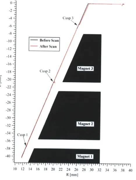
As explained in the prior section, the alternating-polarity configuration creates cusps between each layer of magnets, which are the locations of localized electron flux. As such, these are also the primary locations of erosion for the DCFT. An ero-sion measurement study [7], was performed for the DCFT at the Air Force Research Laboratory. In the study, the DCFT fired continuously for 204 hours in high
cur-rent mode (which will be discussed in the following subsection) and the boron nitride insulator cone's profile was taken before and after operation via a mechanical pro-filometer. The results, in Figure 2-5, reveal the main locations of erosion were at the three cusps, with minor erosion along the exit surface. It is also interesting to note that the location where maximum erosion took place is at the second cusp, where the electron flux to the wall is at its zenith and where it is believed that maximum ionization occurs. 0 -4- Cusp 3 -6--8 -10 - Before Scan -- After Scan -12- -14- -16-- Mgne -18
g
Cusp 2 -20-cus 1 -24 -26- -28- -30--32 --36c -38 -40-10 12 14 16 18 20 22 24 26 28 30 32 34 36 38 40 R Imm]Figure 2-5: Erosion profile of DCFT Insulator Cone after 204 hr longevity experiment performed at the AFRL.
[7]
usually found in Hall thrusters and the incorporation of a divergent channel. In comparison to the annular discharge region of a traditional Hall thruster, the DCFT has a conically-hollow discharge region with a cylindrical anode at the upstream of the base. This design was made to eliminate any erosion which would have taken place in the annular center of the thruster, with the addiitonal reasoning that a diverging channel would also limit erosion on its walls near the exit. An additional benefit of the central pole piece modification includes the facilitatiion of miniaturization of the
DCFT, as per the Princeton CHT.
With a peak anode thruster efficiency of 44%, thrust of 13.4 mN, and specific impulse of 1641 s while operating at an anode potential of 550 V and a flow rate of
8.5 sccm of Xenon [1], the performance of the DCFT is favorable when compared to
commercial Hall thrusters operating at similar power and flow rate.
2.2.1
DCFT Drawbacks
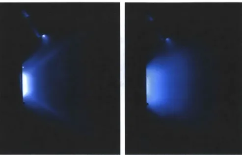
However, there are a number of drawbacks with the DCFT. The foremost weakness of the DCFT is its divergent plume (shown in Figure 2-6), which has reduced thrust and efficiency when compared to a more collimated beam. The expanded plume may also cause damage, through sputtering and deposition, to other satellite components. Also shown in Figure 2-6 are the bimodal operating modes of the DCFT: high-anode-current mode and low-high-anode-current mode. The two modes can be visually dis-tinguished by the plume features. Both modes feature a divergence plume (at 37.50)
and a hollow conical plume. The high-current mode is not desired as the increase in anode current is paired with lowered effiency for a given flow rate. Furthermore, it is hypothesized that the DCFT operating at the low-current mode experiences less erosion than operation in the high-current mode. Unfortunately, operating conditions for mode transition are occasionally difficult to predict and a "mixed" operating mode is often used, where characteristics of both modes are observed.
Last, the divergent channel of the DCFT causes decreased neutral density as propellant travels downstream. This negative gradient of neutral density will lower utilization efficiency if ionization occurs far downstream in the channel.
Figure 2-6: Hollow conical plume of the DCFT operating in high current mode (left), Plume of the DCFT operating in low current mode (right).
2.3
Cylindrical Cusped-Field Thruster Basic
De-sign and Approach
To address the limitations of the DCFT, a new cusped-field thruster was designed. The criteria for the design are as follows:
" Magnetic field lines that begin out of the plume and end at the downstream cusps
" High field strength (>0.5 T) at the cusps
" Low field strength (<0.1 T) outside the mouth of the thruster
" Cylindrical discharge channel
" Flat downstream separatrix, to be discussed in Section 2.3.1
" Comparable discharge region size and number of cusps to the DCFT
These requirements not only fulfill various positive features of the DCFT but may also improve the performance. The first criterion was also used in the DCFT magnetic
topology and facilitates electron travel from a cathode positioned well outside of the plume. The high field strength at the cusps is necessary for the magnetic mirroring of the electrons while the low field strength outside the mouth of the thruster would allow electrons to flow more readily into the channel. The change from a divergent discharge region to a cylindrical region would address the aforementioned issue of decreased neutral density. Last, by maintaining a similar discharge region volume and number of cusps as the DCFT, the effects of the other design changes can be more readily made visible.
2.3.1
Flat Exit Separatrix and Beam Divergence
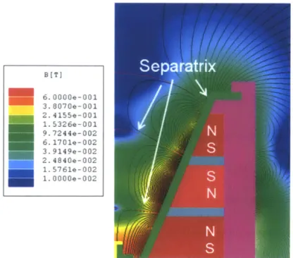
The last design criterion was imposed to address the wide divergence of the DCFTs discharge plume. From previous studies of the divergence [Matlock, 2011], it was found that the ions were electrostatically accelerated out of the thruster perpendicular to the exit separatrix, which is the surface separating
B
lines that go to two different magnetic cusps. The various separatrices of the DCFT are highlighted in Figure 2-7.B[TSeparatrix 6. 00OOe-001 3. 8070e-001 2. 4155e-001 1.5326e-001 9. 7244e-002
N
6.170le-002 3. 9149e-002 2. 4840e-002 1.576le-002 1.00OOe-002N
N
7
S
Figure 2-7: Magnetic topology, field lines and field strength of the DCFT, with the concave sepatrices noted.
Given the convexity of the DCFTs exit separatrix, the plume exiting the thruster would naturally be highly divergent. In an attempt to collimate the beam, Matlock et al experimented with the placement of a focusing electromagnet (operating at 20
A) at the exit of the thruster, as shown in Figure 2-8. In Figure 2-9, the use of the
focusing electromagnet resulted in the thruster plume's divergence visibly decreasing from 37.50 to 21.54.
Flattening
Separatrix
Exit Catp
Figure 2-8: External electromagnet placed at end of DCFT (left), Simulated effect on separatrix from increased magnet current (right). [13]
Imag=0A Imag=20A
Figure 2-9: Plasma plume profile without applied electromagnet (left), Plasma plume
Thus, in order to collimate the beam, the planned design requires a powerful end focusing magnet to produce a flat exit separatrix plane. By placing a permannent magnet, which has higher field strength than the electromagnet, at the end of the magnetic circuit, the new thruster should produce a solid plume, akin to that of a Hall-effect thruster.
2.3.2
Magnetic Source Selection
Following the tradition of the diverging cusped-field thruster, Island Ceramic Grinding Magnetics Samarium-Cobalt 3212 rare-earth permanent magnets were selected for the design's magnetic source. While SmCo-3212 magnets do not possess fields as strong as neodymium magnets, they are used in cusped-field thruster designs because of their thermal properties. Given the relatively high temperatures (2000 C) typically encountered in the DCFT and other plasma thrusters, neodymium magnets would demagnetize after a period of thruster operation. In contrast, with SmCo-3212's maximum operating temperature of 300" C, the CCFT can continuously fire without concerns about damage to the magnetic circuit.
2.3.3
Simulated CCFT Magnetic Field
With these requirements for the new design and chosen magnetic source, magnetic circuits for various cylindrical models were simulated. The simulation package used, Ansoft Maxwell SV, is an electromagnetic field finite element simulation software which was employed in the original design of the DCFT. The simulation employs an axisymmetric, 2D computational domain where geometric shapes are drawn and designated as magnetic material (samarium cobalt magnets, 1018 grade steel), di-electrics (boron nitride, alumina) or non-magnetic (aluminum, graphite). After im-posing Dirichlet null boundary conditions at the boundaries, the magnetostatic solver will determine the resulting magnetic fields from the arrangement of these shapes in the magnetic circuit.
After an iterative process of designing and redesigning various magnetic circuits 34
in order to produce a magnetic topology which would fulfill all of the design criteria, the Cylindrical Cusped-Field Thruster was developed.
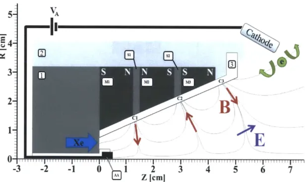
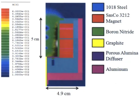
As shown in the axisymmetric magnetic field plot in Figure 2-10, the magnetic topology of the CCFT features magnetic field lines which extend far outside of the exit, a cylindrical discharge channel with the same axial length and averaged radius of the DCFT, and, most importantly, a flat downstream separatrix. As with the Matlock studies, the flat separatrix was created through the placement of a permanent magnetic with alternate polarity at the end of the magnetic circuit.
6 . OOOOe-001 5. 0590:-001 4. 2655e-001 3.5965e-001 3.0324e-001 2.5568e-001 2.1558e-001 1.8177e-001
-
1.5326:-001 1.2922 -001 1.0896-001 9.1868e-002 5 cm 7 .7460e -002 6.5311e-002 5.5066e-002 4 .6431e-002 3.9149e-OC2 3.3009e-002 2. 7832e-002 2 3466e-002 1. 9786e-002 .1 66B3e-002 1. 4066e-002 2.1860-002 1. 0000 -0021018 Steel
SmCo 3212
Magnet
Boron Nitride
Graphite
Porous Alumina
Diffuser
-Aluminum
4.9 cm
Figure 2-10: Magnetic field topology represented by magnetic flux lines within the cylindrical cusped-field thruster, in vacuum.
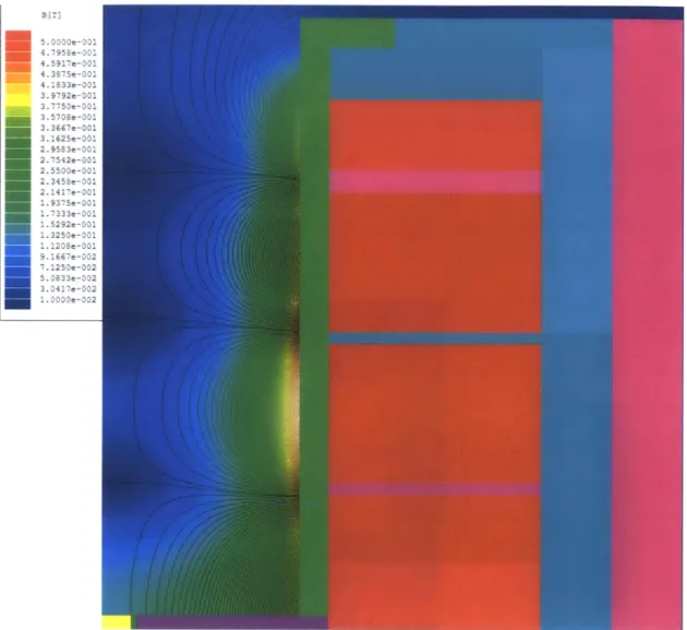
In addition, the high magnetic field strength at the cusps and relatively low field strength at the exit was also achieved, as displayed in Figure 2-11.
2.4
CCFT Thruster Design
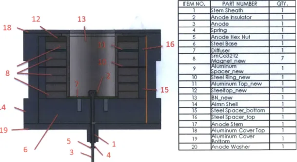
Details of the MIT CCFT prototype are presented in this section, with machine drawings in Appendix A. Figure 2-12 displays the various components featured in the
5.3000e-031 4.7958e-001 4.5917e-11 4.1S33e-001 3.9792e-001 3.7750e-11 3.5708e-001 3.3667e-001 3.1625e-001 2.9583e-301 2.7542e-001 2.55O0e-001 2.3458e-001 2.1417e-001 1. 9375e-001 1.7333e-001 1.5292e-001 1.3250e-001 1.1208e-001 9.1667e-002 7.1250e-002 5.0833e-002 3.0417e-002 1.300e-032
Figure 2-11: Simulated magnetic field strength within the CCFT, in vacuum.
finalized machine drawings of the CCFT in CAD form, with a corresponding bill of
materials.
The following subsections will diskuss key design decisions for critical components
of the CCFT not strictly affiliated with the magnetic design.
2.4.1
Dielectric Insulator Channel
The material used for the dielectric wall of the CCFT diskharge channel was High
Purity (HP) grade boron nitride, purchased from Saint-Gobain Ceramics. The wall
thickness of the cylindrical insert was 2.5 mm throughout the length of the thruster.
12 13 18 16 8 14 19 65 4 3 4
Figure 2-12: CAD cross section and bill of materials for the CCFT.
As with the DCFT, boron nitride was selected due to its ability to sustain high tem-peratures without becoming conductive and thermal conductivity to avoid thermal stress. As noted, it is also a heritage material frequently used in SPT-type Hall thrusters. The existing heritage with SPTs and the DCFT allows for direct compar-isons between the erosion characteristics of the CCFT, of the DCFT, and traditional Hall thrusters. As with the DCFT, the dielectric insert was held loosely in place with an aluminum cap at the exit plane of the thruster, allowing for some axial expansion from possible thermal expansion during operation.
One key difference incorporated in the design of the CCFT insulator is segmenta-tion of the boron nitride. By dividing up the boron nitride tube into smaller secsegmenta-tions, the resulting shorter insulators now have an angle of attack for erosion measurements via ion beam analysis.
2.4.2
Anode Design and Propellant Inlet
For expediency and applicability to the design, surplus DCFT anode stock was used for the CCFT. The anode, composed of graphite due to its high electrical conductivity and excellent sputtering properties, is sheathed in boron nitride to prevent grounding
ITEMNO. PART NUMBER QTY.
I tem Sheath 1
2 ode hsulator 1
3 ode 1
4 pring 1
5 ode Hex Nut 1
6 feel Base 1
7 lffusr r
not ew
9 umnum
10 feel Rin1new
11 uminum Top new 1
12 teeltopnew 1 13 BN new 1 14 mn Shell 1 15 feel Spacerbottom 1 16 teel Spacer_top 1 17 ode Stem I
18 uminum Cover Top 1
19 urinum over 1
Figure 2-13: Boron nitride insulator components (left), Boron nitride insulator, in thruster configuration (right).
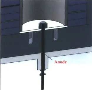
with the thruster body and inserted into the central cavity of the steel base at the furthest upstream section of the diskharge channel. At this point, the anode also helps secure the porous alumina diffuser disk. Additional details for the DCFT anode design can be found in diskussions about the original DCFT design.
Anode
Figure 2-14: Cross section of the anode, with insulating sheath in the steel base.
The steel base, as shown in Figure 2-14, is also where propellant is fed into the thruster. The flow enters from an angled 316 stainless steel tube, welded at the rear of the thruster, into an annular region in the steel base, where it is stagnated by a porous alumina diffuser that distributes it diffused uniformly throughout the disk
and, eventually, into the diskharge channel. Since flexibility was desirable in the installation of the diffuser disk and anode, there is a lack of a perfect seal in the feed system. The diffuser ring was simply set into an inscribed indentation in the steel base and held in place by oversized ceramic washers below the anode, as can be seen in Figure 2-14. As used in the DCFT, this arrangement facilitates changes and modifications to the diffuser without major disassembly of the thruster.
One major difference in the propellant inlet design transitioning from the DCFT to the CCFT is the use of porous alumina, rather than porous type 316 stainless steel for the diffuser disk. This decision was made due to observations of iron deposition on the DCFT insulator cone after hours of operation (as shown in Figure 2-15) is due to sputtering and subsequent redeposition of stainless steel from the diffuser disk.
Figure 2-15: DCFT insulator prior to firing (left), DCFT insulator after firing (cen-ter), Eroded diffuser disk (right). [7]
2.5
Assembly
Due to the relatively high strength of the SmCo-3212 magnets used in the magnetic circuit, there are significant forces between the magnets, which renders assembly a difficult task. In the final arrangement, the repulsive force between the two largest magnets is estimated to be approximately 400N (determined using the Maxwell SV Field Calculator). A system for aligning and safely compressing the magnetic circuit is required for assembly of the thruster.
Machine Press
Steel Base Core
Polycarbonate
Alignment Rod
Screws
Screws
Auminum Casing
Figure 2-16: Schematics of assembly system for the CCFT.
The final design incorporates a polycarbonate rod which is used to align the various magnets and spacers, spaced apart due to the repulsive magnetic forces, collinearly with the aluminum casing. The casing is forced down with a machine press into contact with the steel base, with the magnetic circuit compressed into final thruster configuration. Once the thruster is in place and the press fixed in its location, the aluminum casing is screwed into the steel base core piece, which was modified to ac-commodate several large bolts, as well as the aluminum cover. With this arrangement the magnets and spacers are locked in place using bolts through the steel casing and
into the base core. Once screwed in, the rod is removed from the magnets and, in its place, the porous alumina, ceramic tube insulator and anode are installed. Finally, the aluminum endcap piece is screwed in to secure the boron nitride insulator.
The completed thruster with hollow cathode neutralizer, ceramic wall insulation and test stand is shown in Figure 2-17.
Figure 2-17: CCFT fully assembled, with Busek hollow cathode (left), CCFT in Astrovac with cathode on stage system (right).
2.6
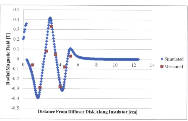
Magnetic Field Measurements
Following the completed assembly of the thruster, an Alphalab DC magnetometer and Hall sensor were used to measure the radial magnetic field strength in the diskharge region of the thruster. These measurements were taken at the cusps and between the cusps along the diskharge wall. The results are shown in Table 2.1.
The results qualitatively and quantitatively match up closely with the Maxwell simulated radial magnetic field strengths, as shown in Figure 2-18. As such, it has been validated that the thruster has been built to design configuration and ready for preliminary testing.
Table 2.1: Measured Radial Magnetic Field Strength
Distance [cm] Magnetic Field Strength [Gauss]
1.0
600
1.8 28702.5
800
3.0
3300
3.5 450 4.0 2800 4.5 800 5.15 300 0 .4 -- --03 0,1 S0 - + Simulated a 4 12 14 Measued 2 -0.1 -0.3 -0.5Distance From Diffuser DiskAlong Insulator [cm]
Figure 2-18: Simulated and measured radial magnetic field along boron nitride insu-lator.
Chapter 3
CCFT Preliminary Results and
Performance
Following assembly, preliminary testing of the CCFT has been performed in the MIT Space Propulsion Laboratory. During the first discharge, voltage and current measurements and visual observations of the CCFT plasma plume were made. In this Chapter, the experimental setup and experimental facilities used for the first trials and results will be discussed in detail.
3.1
Experimental Setup
Figure 2-18 shows the setup was used in the CCFT experiments. As per most thruster performance tests, the thruster body was set at floating potential through the use of an insulator layer, which separated the thruster stand from the chamber, and flexible plastic tubing in the anode propellant line. Due to a lack of knowledge for the optimal cathode position, a cathode stage system was used. The cathode was placed on a 1-axis stage system, which fixed the cathode at an axial distance from the discharge region but allowed for radial traversing. During the first trials, the cathode was continuously repositioned and the resulting changes in the plume were recorded.
For the purposes of the simulation (discussed in Chapter 4), the floating body potential was also measured with a Fluke multimeter.
Figure
SPL.
Cathode .- I-- Heater
(Floating )Power Supply Ground Cathode Stage Power Supply Keeper Power Supply Anode 1g Body Power rneter Supply Cathode Flow Controller Xenon Anode Flow Tank Controller
3-1: Sketch of the schematic of the experimental setup for the CCFT used at
3.2
Experimental Facility and Equipment
3.2.1
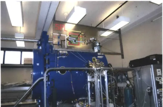
Astrovac
The MIT SPL vacuum facility (ASTROVAC) consists of a 1.5 m x 1.6 m
cylindri-cal chamber equipped with a mechanicylindri-cal roughing pump and two cryopumps
(CTI-Cryogenics CT1O and CTI-OB400 cryopumps), shown in Figure 2-19. The cryopumps
used in tandem are capable of pumping out roughly 7500L/s of Xenon used. The
pres-sure was monitored with a hot cathode gauge, which meapres-sured prespres-sures maximized
at 8.2x 10⁻⁵ Torr while operating at a maximum flow rate of 7.5 sccm.
3.2.2
Cathode
The cathode used for the experiments is the Busek BHC-1500 hollow cathode, which
is commonly used with the BHT-200 low-power Hall thruster and was used extensively
Figure 3-2: The Space Propulsion Laboratory Astrovac vacuum chamber. The
cham-ber, used for the CCFT testing, is pumped by two cryopumps and one mechanical
roughing pump.
for the DCFT. The cathode, which has a porous tungsten hollow insert impregnated
with a low work function emitter comprised of a barium-calcium-aluminate mixture
[14], ignites after using a co-axial tantalum swaged heater wire is heat the emitter to
ignition temperature of approximately 1000
-
1200' C. The ignition is caused by a
keeper, which is used to start the cathode and sustain an internal discharge before
establishing thruster operation [14].
The aforementioned cathode conditioning process involves setting a flow of 2 sccm of Xenon through the cathode and initially setting the heater current at 2 A. After one half-hour, the heater current is increased to 4 A and, another half-hour after that, to 6 A. Five minutes after the heater current is set at 6 A, the cathode is ready to be fired. During normal operating conditions, the cathode operates with 1 sccm of Xe flow and 0.5A through roughly 20V to the keeper, with the heater circuit off.
3.2.3
Power Supplies
Two 1.5k W Agilent N5722A DC power supplies were to supply power to the anode and keeper and operate at a maximum voltage of 600 V and current of 2.6 A, which are more than enough for the required tests. To ignite the cathode and perform conditioning after exposing the cathoding to possible impurities, a HPJA1460PS DC power supply was used to heat the cathode.
3.2.4
Flow Controllers
The cathode and anode flows were regulated using two Omega FMA-A2400 flow controllers, which have been calibrated for Xenon flow and limited to a maximum flow of 10 sccm of Xenon. For all experiments, 99.999% high-purity Xenon gas was used for the anode and the cathode.
3.3
Preliminary Results from First -Discharge and
Stable Operation
3.3.1
Visual Observations of the Plume
The first discharge of the CCFT occurred with low power (100 V on the anode) and a low flow rate (4 sccm). With an increase in anode voltage, the plume became brighter,
with a pronounced solidity along the centerline of the discharge. In both cases, the plume was widely divergent at approximately 450, as seen in Figure 3-4.
Figure 3-4: The CCFT firing with 4 sccm Xe flow and 100 V at the anode (left),
CCFT firing with 4 sccm Xe flow and 200 V at the anode (right).
While the operations are stable within these operating conditions, an increase of anode voltage to above 350 V led to significant arcing between the thruster endcap and the cathode. To mitigate this arcing, the surface of the CCFT endcap was covered in Kapton insulating tape, as seen in Figure 3-5.
With the new thruster configuration, the CCFT was again operated at the same conditions. As a result of the new insulation, the amount of arcing decreased drasti-cally and the plume shape itself has changed. At the same flow rate and potential of 4 sccm Xe and 200 V, the new plume, shown in Figure 3-6, is now far more collimated, with a minor divergence of 15', in comparison to the 450 beam seen in Figure 3-5.
Figure 3-6: The CCFT firing with 4 sccm Xe flow and 200 V at the anode. Increasing the anode potential even further, there appears to be further changes to the plume. In Figure 3-7, there seems to be two plumes emitted from the CCFT: a solid, Hall thruster type beam, with a lower density, divergent (15') plume around it.
3.3.2
Anode Voltage and Flow Scans
With stable operations, the effects of flow rate and anode voltage were explored with flow and voltage scans. The results of these scans can be found in Figure 3-8, Figure
3-9, and Figure 3-10. 1 8-1.6 1.4 X x X *2 scmrn, 0 5 A keeper * 3 sccmn, 0.3 A keeper S8 3 secrn, 0 1 A keeper 06 6 sccn, 0 1 A keeper 0.4 7scorn, 0 1 A keeper 0 2 0 100 200 300 400 Anode Voltage [V]
Figure 3-8: Anode voltage scan, with different keeper conditions. For reference, the complete ionization of 1 seem Xe is equivalent to 0.0718 A of current, assuming single ionization. With double ionization, the current would be 0.144 A.
For the voltage scans, the range of voltages were from 100-375 V, with fixed flow rates at 2 secm, 3 seem, 6 seem, and 7 secm. During the voltage scan, the keeper current was diminshed to presumably decrease the current experienced at the anode. For the flow scan, the anode voltage was fixed and 150 V and 200 V, with flow ranging from 2-7 seem Xe. The voltage did not exceed 375 V because of possible overheating of the anode, and the flow rate was limited due to caution about overly high operating pressures in the chamber.
3.3.3
Anode Current
The critical issue to note is the anode currents, which are higher than the currents found with the DCFT with the same operating conditions, as shown in Figure 3-11
S1.8 1.6 -. T14 1.2 6 6 + Va= 150 V --08 - Va= 200 V 0.6 0A --- - - --- ---0.4 0 4 6 8 10 Flow Rate [sccm]
Figure 3-9: Anode flow scan.
600 500 400 + 2 secm, 0.5 A keeper 300 E 3 sccm, 0 3 A keeper 3 seci, 0.1 A keeper 200 6 sccm, 0.1 A keeper X scecm, 0.1 A keeper W M + 100 A 0 0 100 200 300 400
Anode Voltage [VI]
Figure 3-10: Anode power levels from the voltage scan.
as a reference. They are also higher than expected from full ion conversion of the anode flow, even full double ion conversion.
It can be observed that the anode becomes visibly hot (red-orange color, around 8004 C) when operating at high power, or when a quick transition in anode current