Development and Characterization of a Diverging Cusped
Field Thruster and a Lanthanum Hexaboride Hollow
Cathode
by
Daniel George Courtney
Submitted to the Department of Aeronautics and Astronautics
in partial fulfillment of the requirements for the degree of
Master of Science in Aeronautics and Astronautics
at the
MASSACHUSETTS INSTITUTE OF TECHNOLOGY
uMayne 200May 2008
@ Massachusetts Institute of Technology 2008. All rights reserved.
Author ...
Certified by...
Accepted by...
OFT
AUG 0 12008
LIBRARIES
. ... ...epartment of Aeronautics and Astronautics
May 23, 2008
V... ...Manuel Martinez-Sanchez
Professor
Thesis Supervisor
David L. Darmofal
Professor
As
iate Department Head
Chair, Committee on Graduate Students
Development and Characterization of a Diverging Cusped Field Thruster
and a Lanthanum Hexaboride Hollow Cathode
by
Daniel George Courtney
Submitted to the Department of Aeronautics and Astronautics on May 23, 2008, in partial fulfillment of the
requirements for the degree of
Master of Science in Aeronautics and Astronautics
Abstract
A low power, magnetically confined plasma thruster has been developed and undergone preliminary characterization. The design employs cusped magnetic fields arranged in a divergent fashion to confine electron flow to an anode while providing efficient acceleration of an ion beam, similar to traditional Hall type thrusters. The design, referred to as a Diverging Cusped Field (DCF) thruster, employs aspects of both existing cusped field thrusters and traditional Hall thrusters while including several unique design features aimed at increasing performance. In addition to supporting competitive thrust and efficiency performance, the DCF magnetic arrangement confines the discharge plasma away from the channel walls in order to reduce wall erosion and promote long lifetimes.
The thruster has demonstrated performance levels comparable to typical commercial Hall thrusters. Specifically, a nominal anode efficiency of 44.5% has been achieved while providing 13.4mN of thrust at xenon mass flow rate of 8.5sccm and consuming 242W of anode power. The corresponding nominal specific impulse was 1640s. Preliminary observa-tions suggest that the arrangement successfully contains the plasma away from the channel walls throughout the majority of the discharge chamber. Unique aspects of the DCF dis-charge include an apparent bi-modal operating spectrum and an irregular beam profile. While efficient operation has been observed in both operating modes, the transitions are shown to be accompanied by variations in both ionization efficiency and ion energy distri-bution. The emitted plume was observed to be conical in shape, with a hollow interior and concentrated ion flux diverging at roughly 320.
In addition to the DCF thruster, a small lanthanum hexaboride (LaB6) hollow cathode
has been developed for use with plasma thrusters within the MIT Space Propulsion Labo-ratory. Lanthanum hexaboride was selected due to its insensitivity to impurity poisoning and resultant suitability for experiments which require frequent exposure to atmospheric conditions. The cathode was designed based on larger LaB6 cathodes developed at NASA
JPL. Significant alterations to the design included a threaded ceramic heater and the in-clusion of a thin radiation shield between the cathode tube and keeper electrode. Total current levels between 0.75A and 2.5A were sustained with the external heater deactivated after an initial ignition procedure. Typically the insert had reached temperatures suitable for emission after roughly 30 minutes of external heating at up to 110W of heater power. Thesis Supervisor: Manuel Martinez-Sanchez
Acknowledgments
I would like to thank my advisor, Prof. Martinez-Sanchez for giving me this amazing opportunity and for encouraging me throughout the last two years. Similarly Prof. Paulo Lozano's guidance, assistance and insight has been of immense help for the duration of the project.
My experience at MIT would not have been possible without my funding sources. Specif-ically I would like to thank Prof. Karen Willcox for offering me a last minute teaching assis-tant position when all hope seemed to have disappeared, Prof. Wesley Harris for providing me with funding as a teaching assistant in my second year, and of course my parents for funding the vast majority of my life.
The constant help, advice and all around knowledge of Todd Billings, the MIT Aero/Astro technical instructor, made the experiments presented here a reality.
The generous support of the Busek Company in providing both equipment and test facilities has been extremely beneficial throughout the project to date. Specifically I would like to thank Mike Tsay for performing thrust measurements within Busek.
Finally, I would like to thank all my friends and family who have helped along for the past few years, particularly Mum, Dad, Ashley and Tiz. Noah Warner's help and guidance when I first arrived allowed me to quickly feel welcome in the lab and get involved in research right away. Murat Celik's help both academically and as great friend has been a constant motivator for me to keep at it. Thanks to everyone else at SPL who has helped along the way- Murat, Noah, Bobby, Yassir, Shannon, Blaise, Nareg, Mike and Taylor.
Contents
1 Introduction
1.1 Electrostatic Propulsion . . . . 1.2 Research Overview . . . . 2 The MIT Diverging Cusped Field Thruster Overview
2.1 Review of Traditional Hall Thrusters ... 2.1.1 Performance Metrics ...
2.2 Diverging Cusped Field Thruster Concept ... 2.2.1 Motivation and Comparison with
2.3 DCF 2.3.1 2.3.2 2.3.3 2.3.4 2.4 DCF 2.4.1 2.4.2 2.4.3 2.4.4
Other Cusped Field Magnetic Circuit Design ...
Basic Design and Approach . . .
Magnetic Source Selection . ... Simulated DCF Magnetic Field . Measured Magnetic Field Profile Thruster Design ...
Anode Design and Position . . . Propellant Inlet ...
Dielectric Channel Walls ... Casing and Assembly ...
23 . . . . . 23 ... . 25 . . . . . 27 Thrusters . . 30 . . . . . 36 . . . . . 36 . . . . . 37 . . . . . 39 . . . . . 40 . . . . . 43 . . . . . 43 ... . 45 . . . . . 46 . . . . . 47
3 DCF Preliminary Results and Performance 3.1 Experimental Setup and Facilities ...
3.1.1 Hollow Cathode Neutralizer ...
3.1.2 MIT Space Propulsion Laboratory Facilities . . 3.1.3 Busek Facilities ...
3.2 Experimental Characterization of the DCF Thruster . . . . 55
3.2.1 First DCF Discharge . . . . ... . . . . . ... . 55
3.2.2 Further Testing at SPL ... 56
3.2.3 Thrust Measurements at Busek . . . . 58
3.3 Preliminary Results Summary ... ... ... 65
3.3.1 Observed Bi-Modal Operation ... 65
3.3.2 Cathode Coupling ... ... ... .. 65
3.3.3 Anode and Diffuser Modifications . . . . 66
4 DCF Exploratory Diagnostics 69 4.1 Review of Diagnostic Probe Theory . . . . 69
4.1.1 Faraday Probes ... 69
4.1.2 Retarding Potential Analyzer (RPA) . . . . 70
4.1.3 Interpretation of Results . . . . 71
4.2 Set Up of Diagnostics Equipment . . . . 74
4.3 RPA and Faraday Probe Results ... ... .. 76
4.3.1 Thruster Behavior ... 76
4.3.2 Faraday Probe Analysis ... 76
4.3.3 RPA Probe Results and Analysis . . . . 77
4.4 Summary and Interpretation of Plume Diagnostics . . . . 81
5 DCF Further Observations and Conclusions 83 5.1 Operating Modes of the DCF ... 83
5.1.1 Review of Observed Modes ... 83
5.1.2 Proposed Explanation of Mode Transitions . . . . 84
5.2 Additional Observations ... ... ... . 87
5.2.1 Performance Repeatability and Thermal Concerns . . . . 87 5.2.2 Preliminary Erosion and Plasma Confinement Observations . . . . Relative Performance of the DCF Thruster . . . .
Recommended Studies ... ... . .. 5.4.1 Numerical Simulation ... 5.4.2 Physical Modifications ... 5.4.3 Experimental Studies ... 88 92 95 95 95 96
5.5 Conclusion .. . .
6 LaB6 Hollow Cathode Development
6.1 Introduction ...
6.2 Hollow Cathode Review ... 6.2.1 Thermionic Emission ... 6.2.2 Complete Hollow Cathode Arr 6.2.3 Plume and Spot Mode Operati 6.2.4 Hollow Cathode Plasmas .. 6.3 LaB6 as a Hollow Cathode Emitting
6.3.1 Insert Material Comparison . 6.3.2 Cathode Requirements of the 6.3.3 Available LaBs Insert ....
6.4 LaB6 6.4.1 6.4.2 6.4.3 6.4.4 6.4.5 6.4.6
Hollow Cathode Design. Primary Cathode Tube Orifice Design... Cathode Keeper ... External Heater ... Thermal Considerations . Additional Features .. 99 .. . . .. . . .. . . .. . . . .. . 99 .. ... . 100 .. ... . 100 angement ... 103 ion ... . 104 .. ... . 105 Surface . ... 107 . . . . . 107
fMIT Space Propulsion Laboratory . . 110
. . . 111 .. ... . 112 .. ... . 113 .. ... . 114 .. ... . 119 . . . 120 . . . . . 122 . . . . 123
7 LaB6 Hollow Cathode Characterization 7.1 LaBs Hollow Cathode Testing ...6
7.1.1 Experimental Configuration ... 7.1.2 Cathode Heating and Temperature Measurements 7.1.3 Current Extraction to the Keeper Only ... 7.1.4 Current Extraction to the External Anode .... 7.2 LaB6 Hollow Cathode Performance Evaluation ... 7.2.1 Heating Method ... 7.2.2 Efficient Operating Regimes ... 7.2.3 Comparison with Similar Cathodes ... 7.3 Recommended Future Work ... 7.3.1 Design Modifications ... . 125 . . . . 125 . . . . . 125 . . . . . 126 . . . . . 129 . . . . . 129 . . . . . 137 . . . 137 . . . 137 . . . . . 139 . . . 142 142 98
7.3.2 Experimental Studies ... 143
7.3.3 Theoretical Developments ... ... 144
7.4 LaB6 Hollow Cathode Conclusion ... .... 145
A MIT Diverging Cusped Field Thruster Drawings 153
B MIT Lanthanum Hexaboride Hollow Cathode Drawings 163
List of Figures
2-1 Schematic diagram of the DCF basic operating principles. ... . 23 2-2 Schematic diagram of the DCF basic operating principles. ... . 27 2-3 Sketch of the hollow HEMP type thruster layout reproduced from a number
of sources[l, 2, 3]. Note that it is unclear in the references if the permanent magnets themselves have some variation in inner diameter along the channel. 31 2-4 Schematic of the Princeton CHT thruster and a typical magnetic field profile
(image source [4]). ... 33
2-5 Basic magnetic circuit and design variables considered in developing the final
DCF magnetic circuit ... ... 36
2-6 One of the SmCo magnets used in the DCF prototype, see appendix A for
exact dimensions ... 38
2-7 Magnetic field topology represented by magnetic flux lines within the DCF
thruster, in vacuum. ... 40
2-8 Simulated magnetic field strength within the DCF thruster, in vacuum. . . 41 2-9 Magnetic bottling achieved along field lines with the DCF thruster ... 42 2-10 Measured and simulated axial magnetic field strengths along the DCF thruster
axis. The figure also confirms the presence of a desired axial magnetic trap
in approach to the anode. ... 42
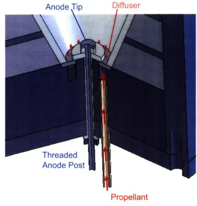
2-11 Cross-section view of the DCF components. ... ... 43 2-12 Partially assembled stainless steel anode and ceramic spacers. ... . 43 2-13 Scale cross section of the anode and fuel assemblies in the DCF thruster.
Propellant is fed through the feed line into an annular channel before diffusing through a porous disc into the channel. . ... . 44
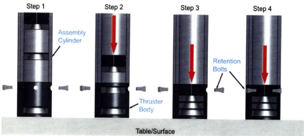
2-14 The HP grade boron nitride cone used to insulate and protect the DCF channel walls. The cone was manufactured by Saint-Gobain Ceramics[5]... 46 2-15 Assembly processes used to compact the DCF permanent magnets . . . . . 47
2-16 Completed DCF thruster.. ... 48
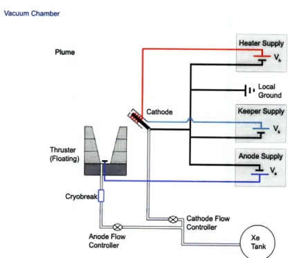
2-17 Assembled DCF and Busek hollow cathode prior to initial testing . . . . . 48 3-1 Sketch of the basic experimental configuration used both at SPL and Busek.
The thruster body was kept floating by insulation between the base and vacuum chamber potential (local ground) and a cryobreak in the propellant
line . ... 50
3-2 The DCF simulated magnetic field showing the approximate locations of the hollow cathode keeper orifice with reference to magnetic flux lines . . . . . 51 3-3 The MIT Space Propulsion ASTROVAC facility used in these experiments.
The chamber is pumped by two cryopumps and one mechanical roughing
pum p. ... .. 52
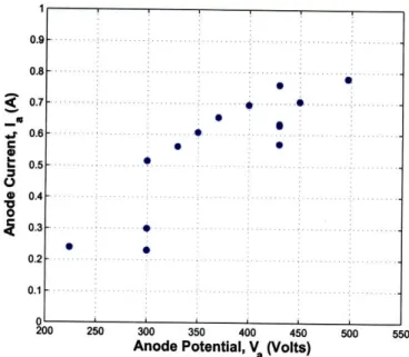
3-4 The Busek company tank T6 which was equipped with a thrust stand. The tank is pumped by a mechanical pump, a diffusion pump and a cryopump. . 53 3-5 Photographs of the thruster in firing configuration at both SPL(a) and Busek(b). 54 3-6 Visible discharge of the first successful DCHT test ... . 55 3-7 Measured anode current with increasing anode potential at a constant flow
rate of 8.5sccm ... 56
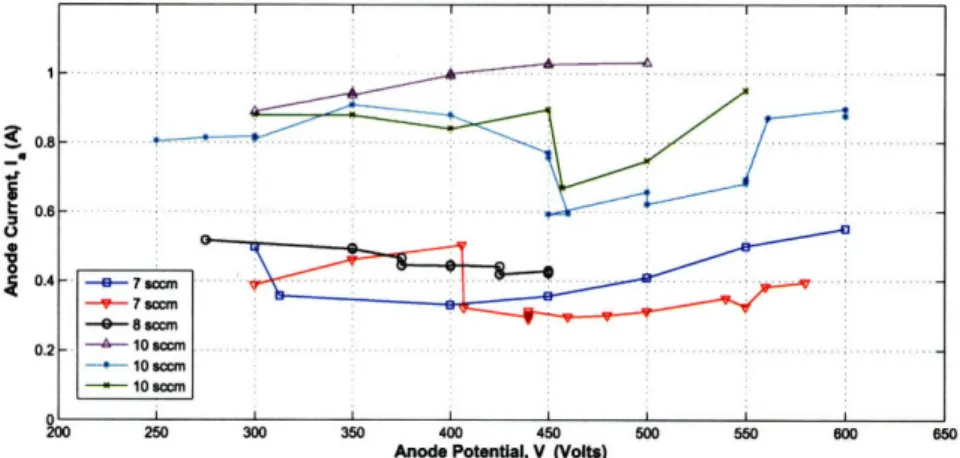
3-8 Anode current with varying anode potential at the flows indicated . . . . . 57 3-9 Photographs of the two characteristic modes of operation of the DCF thruster. 58 3-10 Divergence angle of the visible plume when operating in the low current
mode. When the more diffuse plume is present it appears to be bounded by a cone with a similar angle.. ... .... .... ... . 59 3-11 Simultaneous drop in both anode current and cathode keeper potential during
mode transition. ... .. 60
3-12 Anode current taken at the Busek Company. ... 61 3-13 Keeper potential during scans at the Busek Company. . ... 61 3-14 Anode power anode power levels, the power consumption at the peak
3-15 Thrust measurements taken at the Busek Company, the indicated uncertain-ties represent the standard deviation of the recorded data for each anode
potential. ... 62
3-16 Anode thrust efficiency taken at the Busek Company. . ... 63
3-17 Anode specific impulse measurements taken at the Busek Company. ... 63
3-18 Square root dependence of specific impulse on anode potential. ... . 64
3-19 Simulated magnetic field overlaid onto the visible plume... . . . . .. 66
3-20 The DCF thruster after firing at the Busek company. The material deposited on the walls was electrically conduction. Also note the damage to the anode tip at the center of the channel ... 67
3-21 The original stainless steel anode and the new graphite anode. The anode dimensions were identical ... 68
4-1 Basic construction and operating principles of the type of Faraday probe used in this study (image source[6]). ... 69
4-2 Sample data of a typical Hall thruster angular current density scan using a Faraday probe. The current has been normalized in this example... . 71
4-3 Basic construction and measured signals of the RPA probe used in this study, see Azziz[6] for details. The electron repelling grid is biased below the floating potential at -Ve, while the retarding potential is positively biased at VR. . 72 4-4 Schematic overview of the configuration used when taking diagnostic data of the DCF plume. Both the RPA and Faraday probe were 30cm from the thruster exit plane ... 74
4-5 Diagnostic probes and experimental setup. . ... 75
4-6 Anode current collected prior to collecting the data shown below (April 12, 2008) and current collected while testing at Busek (August 23,2008). In both cases the flow rate was 8.5sccm... 77 4-7 Current density data recorded with the anode potential at 300V, the thruster
appeared to operate in the first, high current, mode during this scan. Angles
4-8 Current density data recorded with the anode potential at 450V, the thruster appeared to operate in the second, low current, mode during this scan. Angles
beyond +450 could not be reached. The spline fit has been cut-off at ±500. 78
4-9 Recorded RPA measurements at Va = 300V with the anode current at 0.69 ±
0.1A and the RPA positioned at -50 from the center line. ... . 79 4-10 Recorded RPA measurements at Va = 300V with anode current of 0.69±0.1A
and the RPA positioned at 280 from the center line. . ... 80 4-11 Recorded RPA measurements at Va = 450V with anode current of 0.53=0.2A
and the RPA positioned at 280 from the center line. . ... 80 5-1 Possible potential profile moving axially along the DCF discharge channel
when operating in the two observed modes. . ... 85 5-2 Selected anode current versus voltage measurements made throughout the
test campaign, both at SPL and Busek. . ... . 87 5-3 Boron Nitride cone after approximately 2 cumulative hours of firing. The
three darkest rings coincide with the magnet boundaries. ... . . 88 5-4 Sketch of the typical erosion patterns observed after firing the DCF thruster.
Darker coloration along the channel walls indicates more deposition. .... . 90 5-5 Photograph of discharge showing brightest regions of plasma separated from
channel walls ... .. ... .. . ... . .. . . .. . .... 91
6-1 A basic hot wire cathode and collector ... .. . 101 6-2 An emitting surface in a plasma. . ... ... 102 6-3 Basic hollow cathode arrangement with keeper. A net electron current is
extracted through the emitted plasma plume downstream of the emitter surface. 103 6-4 Sketches of spot and plume modes in the case where only the keeper is used
to collect electron current ... ... 104
6-5 Sketch of typical axial potential and plasma density variations moving through
a hollow cathode ... 106
6-6 Simplified representation of the processes within BaO-W type emitting surfaces. 108 6-7 Simplified representation of the processes within LaB6 type emitting surfaces. 108
6-8 Emission currents as predicted by equation 6-8. . ... 109 6-9 One of the LaB6inserts used in developing the hollow cathode presented here. 111
6-10 CAD drawing of the assembled cathode. Detailed drawings of each compo-nent, and the complete assembly are presented in appendix B ... 112 6-11 Schematic overview of the assembled LaB6 cathode. Primary components
are indicated and are described in detail during this section. ... 113 6-12 Cathode tube assembly showing retention spring, graphite shunt and LaB6
insert. . . . ... . . .. . . . . .... . 115 6-13 Geometrical parameters affecting hollow cathode design. ... . . 116 6-14 Diameter and flow rate relations predicted to result in the indicated insert
pressures by equation 6.6. The neutral temperature was assumed to be roughly 1700K, or approximately the insert wall temperature during emission. 117 6-15 Simulated vacuum potential distribution at the cathode tip with 600V applied
between the keeper and cathode (ground). . ... 119 6-16 Partial cut-away view of the heater assembly used to heat the cathode insert
to the temperatures required for emission. . ... 121 6-17 Electrical connection slots and thermocouple position. Alumina sleeves
in-sulating the heater and thermocouple wires are shown in position along the cathode tube . ... .. ... .. ... ... .. .. .. .. .. 124 7-1 Sketch of experimental configuration used when characterizing the LaB6
hol-low cathode .. ... ... ... .. .. .. .. .. .. 126 7-2 The LaB6 cathode aligned with the cylindrical, stainless steel anode... . 127
7-3 Measured thermocouple temperatures as a function of time. Heater 1 in-cluded a portion of unprotected wire, the Ta wire for heater 2 was entirely enclosed. In both cases the heater current was ramped up to roughly 4.5A. 127 7-4 Initial and final heater wire configurations. . ... 131 7-5 Keeper voltage with varying cathode flow rates, extracted current as indicated. 132 7-6 Plume mode transitions during flow scans with 1.0A drawn to the external
anode and keeper current as indicated. . ... .. 133 7-7 Plume mode transitions during flow scans with 1.5A drawn to the external
anode and keeper current as indicated. . ... .. 134 7-8 Plume mode transitions during flow scans with 2.OA drawn to the external
7-9 LaB6 hollow cathode operating with the external anode ... . . . . .. 136
7-10 Average power required when operating with the keeper only, for flow rates
less than 2sccm. ... 138
7-11 Total, keeper plus anode, power when extracting 1.0A to the anode. .... 139 7-12 Total, keeper plus anode, power when extracting 1.5A to the anode. .... 140 7-13 Total, keeper plus anode, power when extracting 2.OA to the anode. .... 141 7-14 Cathode to keeper power deposited at minimum (for spot mode) flow rates,
keeper currents as indicated... ... . 141
7-15 Damaged cathode tube after the heater assembly made contact with the keeper electrode during ignition ... . . .. . . ... . . . . . 142 7-16 Cathode after reducing the orifice aspect ration to AR = 0.3. Not all damage
List of Tables
2.1 Summary of the nominal operating conditions for low to mid power Hall thrusters manufactured by Busek[7]. . ... ... 26
3.1 Locations of the Busek hollow cathode during trials. ... 51 4.1 Summary of the diagnostic data presented in section 4.3. ... . 81
5.1 Performance at nominal operating points of the THALES HEMP-T 3050 cusped field thruster, the Busek BHT-200 traditional Hall thruster and the
M IT DCF thruster ... ... 92
6.1 Summary of materials used throughout cathode design process. t The boron nitride used had properties parallel (I1) and perpendicular (1) to the pressing
Chapter 1
Introduction
Current spacecraft propulsion methods can be divided into two broad categories, chemical and electric propulsion. Chemical thrusters rely on the release of energy occurring during chemical reactions. The resultant high temperature products are then expanded through a nozzle and expelled out of the engine. Examples of these thrusters include simple solid rocket boosters and more complex liquid bi-propellant engines. Such devices have been, and continue to be, the primary source of propulsion for launch vehicles. The reason is that, in general, chemical thrusters are capable of very high thrust at the expense of a low specific impulse. Specific impulse, Isp, is defined as the ratio of thrust, T to mass flow, rh, divided by the acceleration due to gravity at surface of the earth. (g = 9.81m/s2).
Ip = T (1.1)
gm
It is clear from equation 1.1 that a high specific impulse is desirable as it implies relatively high thrust for the amount of fuel required. Typical chemical thrusters have a specific impulse less than 450s. The advantages of high I,p can be seen more readily by equation
1.2 which gives the propellant to initial mass ratio for a given AV and specific impulse.
= 1
- e
(1.2)
MO
The mission AV is simply the change in velocity that the thruster is to impart on the spacecraft. From equation 1.2 it is clear that for high specific impulse, the propellant mass decreases.
Electric propulsion thrusters use electrical energy to accelerate the propellant and gen-erate thrust. They include electrothermal thrusters where electric energy is used to simply heat the working gas and, more complex plasma thrusters which accelerate charged parti-cles directly. In general they offer high specific impulse, but often low thrust. Specifically specific impulses ranging from chemical thruster levels to beyond 5000s can be realized with electric propulsion. Thus, in situations where low thrust is acceptable but large AV is required, electric propulsion has a clear advantage over chemical propulsion. Applica-tion examples include satellite staApplica-tion keeping, primary propulsion for deep space missions and earth orbit transfers. For a review of the various forms and applications of electric propulsion, consult Martinez-Sanchez et. al[8].
1.1
Electrostatic Propulsion
Electrostatic thrusters accelerate charged (usually positively) particles through a potential drop to generate a high velocity beam of ions. The reaction to this acceleration provides thrust on the spacecraft. Examples include grided ion thrusters, Hall thrusters and colloid thrusters amongst others[8].
Grided ion thrusters create a discharge plasma then accelerate ions through grids de-signed to admit ions but repel electrons. The resulting thrusters produce a relatively mono-energetic, collimated ion beam and operate efficiently at high specific impulse[8]. However; a significant drawback of grided ion thrusters is that beam current quickly becomes space charge limited through the accelerating grid[9]. The effect being a reduction in the thrust density which can be achieved using the thrusters. Applications of grided ion thrsuters include the NSTAR thruster which propelled the NASA Deep Space One spacecraft from
1998 to
2001[10].
Magnetically confined electrostatic thrusters, like Hall thrusters, accelerate ions through an imposed potential difference but do so within a quasi neutral plasma. The result is that such devices do not suffer from space charge limitation and therefore can achieve higher thrust densities. Despite generally lower efficiencies than grided ion engines[8], Hall thrusters are well suited for satellite station keeping and orbit adjustments. Examples of recent applications include the Busek Company's BHT-200 thruster aboard the AFRL TacSat 2, launched in 2006[7]. This form of thruster will be the focus of this report.
An important component of both grided ion thrusters and Hall type thrusters is the cathode neutralizer. Cathodes provide electrons to both initiate ionization within the pro-pellant gas and to neutralize the emitted ion beam. Without neutralization, emission of an ion beam would quickly charge the spacecraft to a degree where no net thrust is produced. A common form of cathode is the hollow cathode type. Hollow cathodes generate a plasma which couples to the thruster plume through which a net electron current may flow.
1.2
Research Overview
The goal of this project was to explore a new form of electrostatic thruster, the Diverging Cusped Field thruster (DCF). The thruster concept employs an amalgamation of existing technologies and new ideas in an effort to create an efficient, long life electrostatic thruster.
While primarily an experimental proof of concept study, some insight into the operating principles will be offered.
In an attempt to gain insight into the complete electrostatic propulsive unit, this report also details the design and characterization of a small Lanthanum Hexaboride (LaB6) hollow
cathode. The goal of this portion of the project was to develop a hollow cathode which could meet the needs of the MIT Space Propulsion Laboratory for testing various low power thrusters.
Although ultimately designed to operate in tandem, the DCF thruster and LaB6 cathode
will be reported in a decoupled sense. Hence, chapters 2 to 5 are focused exclusively to the DCF thruster while chapters 6 and 7 describe the LaB6hollow cathode.
Chapter 2
The MIT Diverging Cusped Field
Thruster Overview
2.1
Review of Traditional Hall Thrusters
Anode
Figure 2-1: Schematic diagram of the DCF basic operating principles.
Traditional Hall thrusters employ a mostly radial magnetic field across an annular chan-nel as shown in Figure 2-1. For detailed descriptions of Hall thruster physics consult the references[ll, 12, 8]; however a brief overview of the basic Hall thruster operating principles will be presented in order to discuss the similarities, and differences between Hall thrusters
and the DCF thruster.
In a Hall thruster a high potential is applied between the anode and a single, externally mounted, cathode. Electrons, emitted from the cathode are accelerated by near axial electric fields towards the anode. When passing through the magnetic field they begin to drift in a direction perpendicular to the magnetic and electric fields, called E x B drift. The Hall thruster rotational symmetry implies that electrons may drift along closed azimuthal paths. The resulting net drift current is referred to as a Hall current, equation 2.1.
jhau = ene B2 (2.1)
Neutral particles are injected into the channel near the anode to be ionized though electron-ion colliselectron-ions as they flow axially downstream. The electron-ions, whose Larmor radii generally exceed the thruster dimensions, are insensitive to the magnetic field and are accelerated axially by the electric field[ll]. The electrons, moving at the E x B drift velocity do not feel
the electric field in their frame of reference. Ion acceleration occurs through a quasi-neutral plasma. Finally, the ions are combined with an equal current of neutralizing electrons from the external cathode after being expelled from the discharge chamber. A high energy quasi-neutral plasma beam results. Thrust is conveyed to the thruster body via the Lorentz force between the magnets and the current loop created by the confined electrons. This arrangement has advantages over gridded ion thrusters in that is does not suffer from the space-charge limited emission problems of those designs[11, 13]. There are of course, many details involved in Hall thruster operation. An important aspect is the axial transport of electrons through the discharge channel. The mechanisms for electron transport can be largely explained through collisions with heavy atoms both within the discharge chamber, and along the thruster walls[11]. In addition, a departure from classical magnetic diffusion due to turbulent phenomena, sometimes referred to as anomalous or Bohm diffusion, is reported to have a significant effect on the electron transport towards the anode[14].
One draw back of the traditional Hall thruster is that the magnetic field lines inter-cept the channel walls. High electron mobility towards the walls can thus be expected as electron guiding centers tend to follow magnetic field lines. The flux of electrons induces ion attracting sheaths which generate losses both through ion recombination at the walls, and by altering the potential profile within the channel[11]. This last effect can alter the
potential to such a degree that ion acceleration deviates far from the desired axial path. Ions can then be accelerated into the walls or leave the discharge chamber along highly divergent paths[11].When high energy ions impinge on the thruster surfaces the walls may begin to erode. This is a major issue within Hall thruster development[15] as it ultimately limits the thruster lifetime[16].
2.1.1
Performance Metrics
This section introduces some of the observed quantities and performance metrics typically employed when characterizing Hall thrusters. Refer to Fig. 2-1 for some typical quantities of interest for a Hall thruster. The anode current Ia includes both the beam current Ib and the back streaming current Ibs. The back streaming electrons are also referred to as primary electrons as they can dominate ionization of neutral particles. The anode thrust efficiency,
77t given by equation 2.2, relates the beam power to the anode input power (Pa = Vala). The
average specific impulse, described in chapter 1, is calculated using the thrust and anode flow rate as in equation 2.3.In the equations below, T is the thrust produced and rhi is the flow rate through the anode region.
T
2=t
TaP(2.2)
2niaPa
ISp = T
(2.3)
ma9
It can be shown[11] that the anode thrust efficiency can be subdivided into a product of efficiencies as in equation 2.4.
7t = = 7b1uTET/cCOS2 (0b) (2.4)
The beam efficiency Wb, is the ratio of beam current (Ib) to anode current (Ia) and is a
measure of the flux of primary ionization electrons which flow from the cathode into the thruster channel. The utilization efficiency 71, is the ratio of beam current to maximum current obtainable from the flow rate, assuming singly ionized ions. For singly charged ions, the maximum current is hence I, = rhae/m where m is the mass of a Xenon atom (m - 2.18 x 10⁻²⁵kg). The divergence coefficient, cos2(0b) is a measure of the beam
diver-gence, taking into account that only axially directed ions provide thrust in an axisymetric, uniformly distributed plume. Ideally all ions would be accelerated equally through a
po-tential close to the anode popo-tential. The non-uniformity factor, qE accounts for the spread in ion energies. Finally, the charge efficiency 7c accounts for multiply charged ions. The functional forms of these factors are described in more detail in section 4.1 but have been introduced here to gain insight into the benefits of enhancing the various parameters within
Hall thrusters.
When considering the overall thruster and cathode as a unit, both the efficiency and specific impulse are modified due to the power and flow consumed by the cathode. If Pc is the cathode power (generally to the keeper) and irh is the cathode flow rate, the overall propulsive efficiency, 7o is given by equation 2.5.
T2
S=T2
2 (ra + rhc) (Pa + Pc)(2.5)
Similarly, the specific impulse in equation 2.6 is modified to include the cathode flow rate.
* = T (2.6)
(r*ia + rc)g
As the particular cathode properties are not related to the thruster, only the anode efficiency (cathode power/flow are omitted) will be considered when discussing the DCF performance in the following chapters.
Some representative values of thrust, specific impulse and anode efficiency for commer-cial Hall thrusters, manufactured by the Busek Company[7], are presented in table 2.1 to provide context for the values to be reported in the following sections. Notice that anode efficiency tends to increase with power. The increase in efficiency at high power is typical. At low powers energy losses to the thruster walls become increasingly important as the volume to surface area decreases. In addition, low power thrusters require strong magnetic fields which may not be efficiently achievable using typical designs[12].
Power, Pa
IThrust,
T I Specific Impulse,
,p
1200W 12.8mN 1390s 600W 39.1mN 1530s 1000W 58.5mN 1750s 1500W 102mN 1820s Anode Efficiency, r7t 43.5% 49.0% 50.3% 54.6%
Table 2.1: Summary of the nominal operating conditions for low to mid power Hall thrusters manufactured by Busek[7]. Thruster BHT-200 BHT-600 BHT-1000 BHT-1500
2.2
Diverging Cusped Field Thruster Concept
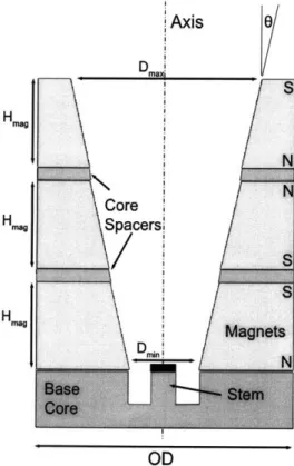
The DCF is schematically illustrated in Fig. 2-2. Three permanent magnets with alternat-ing polarities are arranged in a divergent pattern resultalternat-ing in two strong cusps within the channel and a significant axial magnetic gradient in approach to the anode. The magnetic field strengths within the channel are greatest near the base of the thruster, with decreasing field strengths downstream. The arrangement is intended to magnetically confine electrons streaming from an external cathode. Similar to traditional Hall thrusters a potential dif-ference forms between the anode and the cathode located at the end of the channel. A potential gradient results and ions are accelerated in a quasi-neutral plasma, as in a Hall thruster. This section begins with a description of the DCF concept and its relations with traditional Hall thrusters. Later, the similarities between the DCF and other thrusters with cusped magnetic fields will be discussed. For details of the thruster design, including magnetic field simulations refer to the following sections in this chapter. The DCF thruster
f1 A
I
Anode
Figure 2-2: Schematic diagram of the DCF basic operating principles.
presumably axial electric field between the anode and external cathode, as shown in Figure 2-2. The DCF is, in this respect, related to traditional Hall thrusters and azimuthal Hall currents are anticipated in these regions. However, the magnetic topology obtained us-ing cusped magnetic fields provides several additional mechanisms which contribute to the thruster operation. Mechanisms which are quite distinct from traditional Hall thrusters.
When faced with a magnetic gradient, electron guiding centers feel a repulsive force in opposition to the gradient. The force, given by equation 2.7 is directly proportional the to magnetic gradient tangential to the field line.
F11 = 2B V11B (2.7)
Here v2 is the electron velocity perpendicular to the field. This includes both the cyclotron motion of the electron about its guiding center and the perpendicular motion of the guiding center itself. It can be shown that the proportionality factor on the right hand side of equation 2.7 (the magnetic moment u) is conserved along field lines[17]. Since total electron energy must also be conserved, the invariance of 1L provides a mechanism for magnetic confinement of electrons when the electron energy parallel to a field line goes to zero. The concept is summarized by equating the magnetic moment at two locations along a field line, as equation in 2.8.
V
12
2=
B2 _ 2EK/me - v2 (2(2.8)
Here an electron, with total kinetic energy EK is presumed to move through a magnetic gradient from a region of a given field strength B1 to a region of higher field strength,
B2. The perpendicular energy hence increases at the expense of decreasing parallel energy
until 1/2mev = EK. When fields are arranged to include multiple magnetic cusps a so called magnetic mirror arises where some electrons may be contained between the cusps by multiple reflections at each apex. The ratio of magnetic fields from the point of interest to the maximum field strength along a field line is sometimes referred to as the mirror ratio[18]. This configuration is also referred to as a magnetic bottle.
In the DCF, strong gradients, or magnetic bottles, are present both near the anode and at the magnet cusps. The result is a means for confining electrons both between the anode and first upstream cusp and between the first and second cusps within the channel. This arrangement provides additional electron confinement in tandem with the aforementioned
azimuthal drift currents at the radial field regions. This is in contrast to traditional Hall thrusters where primarily the closed Hall drift currents counter reactive electrostatic forces on electrons by moving them at a velocity where there is no electric field in the electrons reference frame. In addition, the magnetic gradients at the anode serve to inhibit electron flow directly from the external cathode down the center of the discharge channel by creating an axial magnetic trap. Without this feature, electron flow along the thruster axis, where the magnetic field is relatively low, would not be greatly inhibited compared with the regions closer to the channel walls.
Furthermore, the DCF arrangement is designed to reduce wall erosion and ion losses by containing the plasma away from the channel walls. Away from the cusps this is accom-plished by magnetic lines which are mostly parallel to the wall. Electron transport across magnetic field lines is significantly reduced compared to mobility along the field lines[1]. This concept has been employed in ion engines for many years[13]. Therefore in the DCF, when combined with the magnetic gradients at the cusps, mechanisms to reduce electron flux to the walls are present throughout the discharge channel. By reducing electron flux, the sheath potentials required to maintain neutrality at the channel walls are also reduced. As a result a potential profile which avoids accelerating ions towards the walls could be achieved, in contrast to traditional Hall thrusters. Material surface sputter rates will de-crease as both the ion flux and incident energy are reduced. Therefore the arrangement provides a means for reducing wall erosion within the channel. It should be clarified that in this description the ions are not assumed to be magnetized. Rather the potential profile, which is strongly influenced by the magnetically confined electrons affects the ion paths. In addition, such confinement represents an efficiency enhancement, avoiding energy lost when ions and electrons recombine/impact the walls. In summary, the DCF concept may both reduce energy losses to the thruster walls and increase thruster lifetime through reduced wall erosion.
Finally, the DCF features a divergent shape intended to further enhance performance. Most simply the divergent shape reduces losses of ions by increasing the range of trajectories that do not intercept the walls. However; the shape was motivated by several more subtle factors. As described above, the additional magnet creates a complete mirror between the two mid channel cusps. By further confining electrons in this region a secondary ionization region between the cusps could result. The third magnet continues to provide fields parallel
to the walls while the field strength gradually decreases due to the divergent shape. This feature was motivated through observations that similar cusped field thrusters tend to have a highly divergent dischare[19]. It was postulated that given the high field strengths expected within the thruster ions may become weakly magnetized as they pass through the discharge channel. Therefore the divergent shape was intended to gradually reduce the magnetic field strength exposed to axially accelerated ions. as they progress from the first cusp towards the exit plane. A gradual reduction was selected to minimize the deflection of ions at the exit plane where the magnetic field curves sharply. Details of the magnetic circuit design and the expected magnetic field are provided in section 2.3
There are a few potential drawbacks of the DCF concept. First, the divergent channel will result in decreased neutral density along the channel. Therefore, if ionization is not completed in the low diameter upstream region, efficient ionization of the propellent may be difficult. On the same note, it is possible that if the magnetic confinement is too great and the plasma is confined a significant distance away from the channel walls, neutrals could stream between the walls and plasma without being ionized. Secondly, the localized electron confinement between the anode and first cusp, and at the second cusp could result in two stage behavior. The result would be a bi-modal distribution in ion energies, which by equation 2.4 is undesirable.
In summary, when compared to traditional Hall thrusters the DCF thruster concept enhances electron confinement beyond the E x B closed drifts through magnetic mirroring. Also, the DCF thruster is designed to reduce wall losses through constant magnetic protec-tion of the thruster walls, either through parallel fields or strong magnetic mirrors near the cusps and anode.
2.2.1
Motivation and Comparison with Other Cusped Field Thrusters
The DCF design was primarily based on the experience gained from previous thrusters which employ cusped magnetic fields. The basic magnetic circuit stems from the highly success-ful, although not well understood, THALES High Efficiency Multi-stage Plasma(HEMP) thrusters[18, 20, 19]. In addition, the DCF also amalgamates features of the Princeton Cylindrical Hall Thruster (CHT) [21]. This section first describes the proposed operat-ing principles of these thrusters than reviews similarities and unique aspects of the DCF thruster concept.THALES High Efficiency Multistage Plasma Thrusters (HEMP)
The HEMP thrusters have been derived from Traveling Wave Tube (TWT)
technolo-I
Axis
Cusps
Walls
Figure 2-3: Sketch of the hollow HEMP type thruster layout reproduced from a number of sources[1, 2, 3]. Note that it is unclear in the references if the permanent magnets themselves have some variation in inner diameter along the channel.
gies used to amplify RF signals in communication satellite applications. Several itera-tions of the HEMP concept exist[2]. The DCF most resembles the HEMP-T 3050 class of thrusters which, according to recently presented results[l], have a nominal anode efficiency of rlt = 46%, producing 50mN of thrust with an input power of 1500W. HEMP thrusters
use three permanent magnets arranged as in Figure 2-3. The periodic permanent magnet arrangement used in the DCF was inspired by the HEMP thrusters. The concept of using cusped fields to provide both radial field regions, to initiate Hall currents, and wall pro-tection through near parallel fields away from the cusps was also initiated with the HEMP design[3, 22]The DCF adds to this an important feature, namely a central magnetic pole providing a magnetic mirror at the anode approach. Variation in the channel geometry and the exposed magnetic field strength appears to be obtained by some combination of varying the material thickness between the discharge chamber and the permanent magnets[l] and
varying the magnets themselves. However; the exact magnetic configuration is unknown. HEMP thrusters are designed to have a very strong magnetic cusp near the exit plane and two weaker cusps within the discharge channel[18]. The arrangement is claimed to isolate the thruster ionization region to the channel section upstream of the exit plane cusp[18]. Within this region, the combination of magnetic mirrors and field lines parallel to the wall are intended to dramatically reduce electron losses to the walls[19] yielding very high beam efficiencies (back streaming currents of a few percent of the anode current) [18]. The anode is not protected explicitly by the magnetic field lines, rather it is possible that the magnetic mirror between the two mid channel cusps inhibits electron flow to the anode. The apparent beam divergence of the plume emitted from HEMP thrusters varies between reports[23][18]. Visually a divergent cone can be seen, with some reports indicating that the discharge forms a hollow cone of high energy ions[18]. In the cited reference, cone divergence angles around 35% are reported. However; recent experimental data suggests a more diffuse high energy beam profile centered about the thruster axis has been achieved in the latest iteration of the design[23].
Princeton Cylindrical Hall Thruster (CHT)
The Princeton Cylindrical Hall Thrusters[21, 15, 24] employ both an annular region of highly radial magnetic flux lines and a cylindrical region which features a strong magnetic bottle and cusp towards the exit plane. In all reported iterations of the thruster to date, the magnetic field levels are below 1700G, about 1/3 of the maximum field strengths in the DCF (see section 2.3). Hence the confinement region in the CHT is likely to be more diffuse than in the DCF. Sketches of the CHT thruster and magnetic field topology are shown in Figure 2-4. Here the magnetic fields are produced by electromagnets (allowing for optimization of the field[25]), and a ring shaped anode is located at the base of the coaxial region, unlike the central location chosen for the DCF. The CHT thruster has been designed to promote ionization in the coaxial region with ion acceleration confined to the cylindrical portion of the thruster. This isolation is stated to occur by designing the coaxial region to be approximately equal to the neutral mean free path for ionizing collisions [15]. The ion acceleration is then presumed to take place in the cylindrical region of the thruster. A lo-calization of potential gradients in the cylindrical region has been confirmed experimentally using internal probe measurements[26].
core (a) ode-neutralizer anic Chon"e
"
Mirror
Plug
I
Mirror Plug Thruer axis
Figure 2-4: Schematic of the Princeton CHT thruster and a typical magnetic field profile (image source [4]).
The cusped structure and magnetic mirror in the cylindrical region are intended to trap electrons, and hence neutralize space charge, both through the typical Hall current traps and by the magnetic gradient forces[15]. This application of magnetic mirrors specifically to confine electrons in the expected acceleration regions distinguishes the CHT from traditional Hall thrusters. Unlike the HEMP thrusters described above, where magnetic cusps are found only along the thruster wall, the CHT central cusp produces an axial force on the electrons. Therefore, as in the DCF, the CHT magnetic field may counter the reactive force on electrons due to both the closed Hall currents and the axial magnetic gradient forces. In addition, the cylindrical region is intended to reduce ion losses by enhancing the volume to surface area ratio in the acceleration region[21].
The CHT thruster has been largely optimized for small low power applications where the large volume to surface area ratio and strong magnetic fields are highly desirable[15]. Specifically, the 3cm diameter iteration of the CHT operates consistently with anode
effi-ciencies above 20% at anode powers as low as 100W while promising longer lifetime than
I Magnelic Circuit I
traditional Hall thrusters through reduced channel wall erosion[27]. The beam divergence of CHT thrusters can reach 800 in some circumstances, although the most recent optimiza-tions of the field profile have reduced this angle significantly[15].
MIT Diverging Cusped Field Thruster (DCF)
Although the periodic permanent magnetic arrangement of the DCF thruster bears a strong similarity to the HEMP thrusters, the DCF also resembles the CHT thruster with the coax-ial region removed. CHT type thrusters with no coaxcoax-ial region have been developed[28], however; even in this circular cross section case, the anode is place in a region of predomi-nantly radial magnetic field lines which intercept the thruster walls.
The anode position is one of the key distinguishing features of the DCF thruster com-pared to both the HEMP and CHT designs. In the DCF the anode is intentionally placed at the apex of the magnetic bottle to reduce electron flow and facilitates strong variations of this flow via the ability to make small adjustments of the anode's axial location. In the HEMP thrusters the electron flow is presumably inhibited by means of mirroring between the first and second magnetic cusps closest to the anode. The anode itself does not appear to be directly protected by a magnetic bottle. As described above the, in the CHT a ring shaped anode is placed in a region of predominantly radial fields very similar to traditional Hall thrusters.
Both the THALES and Princeton designs claim to separate ionization and acceleration regions within the discharge channel. However, in a 1D arrangement, it is known that the potential drop and hence ion acceleration starts in the ionization layer and becomes steep just beyond it[29]. In analogy to the Chapman-Jouguet detonation condition, the sonic condition (vi = (kTe/m i)1/2) occurs precisely at the exit from this ionization layer, the
flow being supersonic downstream. In the DCF, the ionization region is likely to have a more complex 3D topology, defined by the dominant magnetic bottle; however the same physics should prevail and we expect strong ion acceleration at just the exit of this ionization region. This would seem to negate the possibility of a clean separation between ionization and acceleration regions, as suggested in both the HEMP and CHT thrusters. As a result, in the DCF we anticipate both ionization and acceleration of ions to be strongly localized in combined magnetic bottle and azimuthal drift current traps.
through parallel fields and the magnetic cusps. However, this protection has been specifically optimized[18] to contain electrons within a presumed ionization region upstream of the exit plane. Again, this differs from the DCF where separation of ionization and acceleration regions was not assumed and acceleration is presumed to begin in the region between the anode magnetic bottle and first cusp.
Recent iterations of the THALES HEMP thrusters also feature a divergent pattern[11. However; the detailed design is not divulged and the divergence may occur only between the second and third cusps and may be created via the channel wall shape only, not through use of continuously divergent magnets as in the DCF.
The DCF is thus a combination of both the CHT and HEMP concepts designed to employ favorable qualities of both, in addition to new features aimed at improving the overall thruster performance, in order to produce an efficient long-life thruster. It is important to recognize that while the two references cited here bear the greatest resemblance to the DCF thruster, and have been the primary motivation of the design, there have been several previous thrusters employing magnetic mirrors or cusp fields. For example the Kaufman End-Hall ion source[30], relies primarily on axial forces from magnetic gradients to prevent electron motion towards an anode positioned at the base of the mirror. The anode location of the DCF is thus similar to this design.
2.3
DCF Magnetic Circuit Design
This section reviews the magnetic circuit designed to meet the conceptual requirements of the DCF thruster which were outlined in the previous section.
2.3.1 Basic Design and Approach
The DCF magnetic field topology was developed using Ansoft Maxwell SV[31] software
to simulate the fields produced by various magnetic configurations. Numerous simulations were performed in an effort to produce a magnetic circuit which captured all the of the conceptual benefits of the DCF concept which were outlined in section 2.2. These include (i)strong magnetic mirrors, (ii)protection of the thruster walls and (iii) a gradually decreas-ing magnetic field within a divergent channel. It is important to stress that the exploratory nature of this prototype design did not allow for highly quantitative development of the field, rather a more intuitive approach was taken at this time. Figure 2-5 shows the basic
OD
Figure 2-5: Basic magnetic circuit and design variables considered in developing the final DCF magnetic circuit.
magnetic circuit and geometrical factors which were varied in developing the design. The three permanent magnets are complemented by soft steel (1018 grade Carbon Steel) spacers and a large core at the base of the structure. The spacers help focus and modify the cusp field geometry. The base core was designed to channel magnetic flux into the core stem shown in the figure. The basic scaling dimensions of the thruster are on the same order as Hall thrusters with similar expected power consumption and operating performance. For example the Busek[7] BHT-200 Hall thruster[16] which has an annular channel roughly
20mm in length with ID 20mm, OD 30mm. In the DCF, the magnet diameter at the base
of the discharge channel, Dmin was fixed at 20mm. The channel length from the anode to the first cusp was set by the first magnet thickness, Hag to be 12.5mm. For simplicity the magnet thicknesses and outer diameters were held constant. The outer diameter of all mag-nets, OD in the figure is 64mm. Given that the quantitative effects of the divergent shape were not known during the design phase, the wall angle, 0, was set to 22.50. This angle was selected for the prototype design to provide significant reductions in the field strength along the channel while maintaining a relatively small area, and hence high neutral density, near the thruster base where the majority of ionization is expected to occur. The size of the magnets thus decreases moving axially from the anode, resulting in reduced field strengths in the channel, as desired.
Further design variations focused on the core structures, both at the base and the spacers between the magnets. Magnetic flux was focused through the thruster axis by incorporating an annular channel in the base core structure, resulting in the core stem indicated in the figure. The annulus thickness and depth were varied in order to maximize flux through the stem while avoiding saturation of the steel and maintaining mostly parallel field lines along the magnet walls. The core spacer thicknesses were adjusted to ensure regions of mostly radial field which were several mm in thickness (comparable to the confinement region of traditional Hall thrusters[121), while also ensuring strong magnetic bottling at the cusps.
2.3.2 Magnetic Source Selection
In order to create the desired magnetic topology, permanent magnets were selected over electromagnets. This decision was made given the high field strengths desired, the required complexity of the field topology, and the electrical power savings inherent in using per-manent magnets. For a basic review of perper-manent magnet properties and design criteria
the reader should consult one of the references[32, 33]. In this application we required a magnetic material which could maintain a strong field both at elevated temperatures and in the presence of other magnets with inverted polarities (at the cusps).
Rare earth Neodymium Iron Boron (NdFeB) and Samarium Cobalt (SmCo) magnets were considered given their high field strengths[32]. SmCo was ultimately selected given its good thermal properties and resistance to demagnetization. Specifically, type 3212 SmCo supplied by Dexter Magnetics[32] was used. The B versus H hysteresis curve supplied by the manufacturer is available in appendix C. The quoted residual induction of this material (in effect the expected surface field strength when isolated from demagnetizing forces) is 11.5kG, or 1.15T. Samarium Cobalt has a high intrinsic coercivity of 12kOe at 2000C, meaning it maintains a high intrinsic field in the presence of demagnetizing fields. The listed maximum operating temperature is 30000C, above which permanent reductions in the field can be expected. The specific impact on intrinsic coercivity due to elevated temperatures can be found in the appendix. The Curie temperature, where the material losses its ferromagnetic properties, is 825'C. The thermal behavior is a concern given that typical SPT type Hall thrusters can have wall temperatures around 4000C[16]. As a result some field degradation could occur; however, if the magnetic confinement desired in the DCF is effective, the wall temperature may be much lower.
Figure 2-6: One of the SmCo magnets used in the DCF prototype, see appendix A for exact dimensions.
through considering the conceptual description in the previous section. In traditional Hall thrusters an excessive magnetic field can effectively choke electron flow to the anode, hence restricting operation of the thruster. However, in the DCF concept an excessively high magnetic field will simply serve to contain the plasma further from the chamber walls within the magnetic mirror where the field strength is lower. Since the field goes to zero between the cusps on the thruster axis it is presumable that the operation would be only weakly affected by the specific field strength at the chamber surfaces. Severe magnetic bottling at the anode, which could prevent electron flow as in traditional thrusters, can be overcome by varying the anode position within the field geometry. Such a feature has been employed in the prototype design and will be discussed shortly, in section 2.4.1.
2.3.3 Simulated DCF Magnetic Field
The simulated magnetic flux lines and magnetic field strengths of the DCF thruster, in a vacuum, are shown in Figures 2-7 and 2-8 respectively. The flux pattern shows that both regions of radial magnetic field and strong magnetic bottles were achieved at each cusp along the channel. In addition a strong bottle is achieved at the anode. The non magnetic components shown in Fig. 2-7 will be reviewed in the following sections. Referring to Fig. 2-8, the magnetic field strength in the channel ranges from zero, along the thruster axis at the cusp positions, to roughly 0.5T near the channel walls. This peak strength is approximately three times the maximum(- 1.7kG) found within the Princeton CHT thrusters[15]. The magnetic field is seen to decrease moving axially along the discharge channel as desired. Given these fields, some quantification to the claims in section 2.2 that ions could be weakly magnetized can be made. The Larmor radius, given by equation 2.9, for a Xenon ion (mi = 2.18 x 10⁻² 5kg), accelerated through a 300V potential (perpendicular to the field) in a 0.5T magnetic field is approximately 60mm.
v± _i2eV/mi(
rL = - - (2.9)
we eB
The Larmor radius is thus on the order of the thruster dimensions so some weak interactions could occur(17]. However; given that the maximum field has been used in this calculation, the effects on most ions may not be as significant as first expected.
1018 Stee
SmCo 321 Other
O ý Mawrkc
~d
Figure 2-7: Magnetic field topology represented by magnetic flux lines within the DCF thruster, in vacuum.
anode is given by Figure 2-9. In the figure, the tangential magnetic field strength is shown following a field line which intercepts the anode. In this example, the tangential field gradi-ents are approximately 30T/m and 60T/m in approach to the anode and cusp respectively. Along this field line the ratio of maximum to minimum field, the maximum mirror ratio, is approximately 3.8. Such ratios are difficult to compare given that the minimum field varies radially. However; ratios of similar magnitude are reported in the strongest cusp (at the exit plane) of the THALES HEMP thrusters[18]. Furthermore, both Figs. 2-8 and Figure 2-10 show that an axial magnetic trap has been achieved in approach to the anode. As described in section 2.2, this feature was desired in order to prevent electron flow from the cathode to the anode directly along the thruster axis.
2.3.4 Measured Magnetic Field Profile
Experimental confirmation of the magnetic field was carried out with an AlphaLab DC Magnetometer[34] accurate to within ±2%. The probe dimensions were generally larger
Figure 2-8: Simulated magnetic field strength within the DCF thruster, in vacuum. than the length scales of variation within the thruster field, as a result only the field along the thruster axis could be measured accurately. Comparisons between the measured and predicted fields are shown in Fig. 2-10. Good agreement was achieved. Some uncertainty in axial position existed due to the enclosed nature of the probe. The two experimental curves were measured approximately one year apart, during which time all thruster data to be presented in this report were collected. The results show that minimal degradation of the field has occurred throughout the test campaign.
Figure 2-9: Magnetic bottling achieved along field lines with the DCF thruster.
-n
0 10 20 30 40
Distance From Core (mm)
50 60
Figure 2-10: Measured and simulated axial magnetic field strengths along the DCF thruster
axis. The figure also confirms the presence of a desired axial magnetic trap in approach to the anode. - - - Maxwell Simulation S"* April 14 2007 S0. April 17 2008 - ... ..* \ ... . ... .. .. . . 0*\ O\ o\ 0\ 00 .'.
![Figure 2-4: Schematic of the Princeton CHT thruster and a typical magnetic field profile (image source [4]).](https://thumb-eu.123doks.com/thumbv2/123doknet/14731826.573133/33.918.348.588.116.540/figure-schematic-princeton-thruster-typical-magnetic-profile-source.webp)