Developing a Radio Frequency Enclosure for the
Multiplicity Vertex Detector of the PHENIX Experiment
by
Richard Conway
Submitted to the Department of Mechanical Engineering
in partial fulfillment of the requirements for the degrees of
Bachelor of Science
and
Master of Science in Mechanical Engineering
at the
MASSACHUSETTS INSTITUTE OF TECHNOLOGY
May 1999
© Massachusetts Institute dTTechnology f99. All rights reserved.
Author - rz k--- Z
Department of Mechapo KEngineering
18, 1999
Certified by
Woodie C. Flowers
Pappalardo Professor of Mechanical Engineering
Thesis Supervisor
Accepted by
Amn A. Sonin
Chairman, Department Committee on Graduate Students
Developing a Radio Frequency Enclosure for the
Multiplicity Vertex Detector of the PHENIX Experiment
by
Richard Conway
Submitted to the Department of Mechanical Engineering
on May 18, 1999, in partial fulfillment of the
requirements for the degrees of
Bachelor of Science
and
Master of Science in Mechanical Engineering
Abstract
The Radio Frequency Enclosure is an environmental shield for the
Multiplicity Vertex Detector, which is a central subatomic particle detector in the
PHENIX physics experiment being performed at the Relativistic Heavy Ion
Collider at the Brookhaven National Laboratory. The RF enclosure is designed to provide mechanical protection of the MVD and isolate it from external RF noise, temperature, and humidity while adding as little mass to the detector as possible.
The RF shielding is made of a thin aluminum foil, and Mylar film is used to keep out the external air. Rohacell foam, a high strength and low density
polymethacrylimide foam, is used as the structural support for the enclosure, which helps to minimize the added mass.
The RF enclosure design was developed to the production stage. During the development process, the details of the fabrication, assembly, and installation procedures were finalized and then documented. Additionally, all the tools and fixtures needed for fabrication, assembly, and installation were designed, built, and tested. A prototype enclosure was tested for RF attenuation and air leakage, and the results of both tests indicate that it will adequately shield the MVD's
internal components.
Thesis Supervisor: Woodie C. Flowers
Acknowledgments
Thank you to my parents for their love and encouragement throughout my term here at MIT. Without them I would have neither had the opportunities or taken advantage of the opportunities that have come my way. Their guidance has been
flawless in both frequency and amplitude.
A great thank you also goes to Jehanne Simon-Gillo for her sincerity and
willingness to give her time and financial support to my part of the project. Thanks to the whole MVD team for their experienced advice, as well. My project would
not have been completed without their help.
Professor Flowers also deserves thanks for his willingness to take me under his wing for the duration of the project. The Engineering Internship Program's coordinator, Karl Reid, has put more effort into making the program great than
anyone could have ever expected. Thank you.
Finally, I would like to thank Rachel Cunningham, Daniel Keating, Eugene Lee, Shahram Tadayyon, and Amy Kukla for their steadfast encouragement and
Table of Contents
Section
Page Number
1 Introduction 9
1.1 Overview of work 9
1.2 Overview of RHIC 9
1.3 Overview of PHENIX 10
1.4 Overview of the MVD 11
1.5 Overview of the RF Enclosure 13
2 General notes on RF noise and shielding 16
2.1 What is RF noise? 16
2.2 The need for shielding 16
2.3 RF shielding 17
3 Isolating the MVD from the outside environment 20
3.1 Isolation from RF noise 20
3.2 Isolation from air leaks 21
3.3 Isolation from temperature gradients 24
4 Building the Inner RF Enclosure 26
4.1 Thermoforming properties of Rohacell IG-71 26
4.2 The Inner RF Enclosure Thermoforming Procedure 27
4.3 The Inner RF Enclosure Machining Procedure 31
4.4 The Inner RF Enclosure Assembly Procedure 31
4.5 The Inner RF Enclosure Installation Procedure 34
5 Building the Outer RF Enclosure 38
5.1 The Outer RF Enclosure Thermoforming Procedure 38 5.2 The Outer RF Enclosure Machining Procedure 42
5.3 The Outer RF Enclosure Assembly Procedure 47 5.4 The Outer RF Enclosure Installation Procedure 48
6 Testing the RF Enclosure Prototype 53
6.1 Testing the RF Shielding Capabilities 54
6.2 Testing the Air and Humidity Tightness 57
7 Conclusions/ Recommendations 59
8 Appendices 60
8.1 RF shield attenuation estimations 61
8.2 Thermoforming Rohacell 62
8.3 The Inner Radio Frequency Enclosure 98
8.4 The Outer Radio Frequency Enclosure 110 8.5 Prototype RF Enclosure attenuation test data 135
Section 1: Introduction
1.1 Overview of work
This paper summarizes the work that I have performed in researching, designing, fabricating, assembling, installing, and testing the Radio Frequency (RF) Enclosure of the Multiplicity Vertex Detector (MVD). Testing has shown that the design can be fabricated, assembled, and installed so that tolerances on all specifications can be met and that the RF enclosure can adequately perform the tasks required of it.
The RF enclosure is a component of the MVD. The MVD is a subatomic particle detector in the PHENIX Experiment, which will be operated at the Brookhaven National Laboratory's Relativistic Heavy Ion Collider (RHIC).
1.2 Overview of RHIC
The Relativistic Heavy Ion Collider (RHIC) is a particle accelerator being built at the Brookhaven National Laboratory (see Figure 1-1).
PHOBOS BRAHMS RHIC PHENIX STAR AGS Hooste -Linac -Polarized H Surcm Figure 1-1: The Layout of RHIC at BNL
It will have the capability of colliding heavy ions at energies of 100GeV in each beam.1 Quantum Chromodynamics (QCD) predicts that heavy nuclei collided at these ultra-relativistic energies will undergo a phase transition from ordinary
hadronic matter to a quark-gluon plasma (QGP). 2 QGP is the as-of-yet unseen form of matter believed to have existed immediately after the Big Bang.
Four major experiments: PHENIX, STAR, PHOBOS, and BRAHMS, are under construction at RHIC in order to study QGP physics as well as the physics of polarized proton collisions.1 RHIC is scheduled to become operational in the Summer of 1999. The first RHIC heavy ion physics run will commence in the Fall
of 1999.3
1.3 Overview of PHENIX
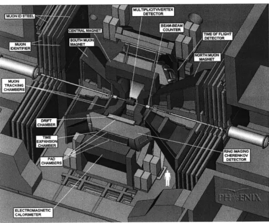
Figure 1-2: The PHENIX experiment's detector layout
Obtained from http://www.phenix.bnl.gov/exportl/docs/html/RHIC.html Obtained from http://www.phenix.bnl.gov/phenix/WWW/html/physics.html Obtained from http://www.phenix.bnl.gov/phenix/WWW/home/phenix_5w.htm
1.
2.
PHENIX is a very large particle detection experiment, which is designed to
detect, identify, and measure the characteristics of each of the many different kinds of particles (electrons, muons, hadrons, and photons) produced at RHIC.
PHENIX is comprised of four magnets, four instrumented spectrometers or arms
(two electromagnetic and two muon arms) and two inner detector subsystems (see Figure 1-2). The PHENIX Collaboration consists of over 430 physicists and engineers from 43 participating institutions in 11 countries (Brazil, Canada, China, Germany, India, Israel, Japan, Korea, Russia, Sweden, and the USA). A
comparable number of support personnel also work on PHENIX.3
Among the major goals of PHENIX are: 1) investigating the Quantum Chromodynamics prediction of a deconfined high-energy-density phase of matter, 2) searching for the quark gluon plasma, and 3) exploring the physics of this new state of matter. PHENIX will also study the physics of polarized proton collisions in order to uncover the secrets of the spin structure of the proton. Currently it is known that the three quarks do not carry all of the spin of the proton. The rest of the spin might be carried by the gluons, sea quarks, some combination of these or
by some as yet undiscovered mechanism.2
1.4 Overview of the MVD
The Multiplicity Vertex Detector (MVD) is the innermost detector of the
PHENIX experiment. The MVD's main physics goals are: 1) to provide a
multiplicity measurement (dN/drj) to the PHENIX Level-1 trigger, 2) to measure fluctuations within the multiplicity distribution on an event-by-event basis (which potentially can be associated with the formation of Quark Gluon Plasma), and 3) to determine the collision vertex. The detector has full azimuthal coverage with good granularity and is capable of reconstructing the collision vertex to
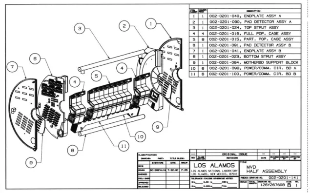
Figure 1-3: Exploded assembly drawing of one half of the MVD
The MVD is a clam-shell design, constructed in two halves to close about the beam pipe (see Figure 1-3). The 64cm long central barrel of the detector is comprised of two concentric layers of silicon strip detectors located at 5cm and 7.5cm from the beam. There are 112 strip detectors with 256 strips on each detector at 200mm strip-pitch. On each end of the central barrel there is a silicon disk comprised of twelve wedge-shaped pad detectors. Each pad detector has
252 elements that increase in size from 2mm x 2mm at the inner radius to 4.5mm
x 4.5mm at the outer radius.4
Each silicon strip and pad is read-out independently. This requires that there be a tremendous amount of signal processing performed inside the MVD. The detector front-end electronics must have the ability to continually process
data at an estimated maximum rate of one collision event every 1 0Ons. These front-end electronics are encapsulated in several custom CMOS chips which
house a preamplifier, discriminator, analog memory unit, and analog to digital converter. The system has pipelined acquisition, performs in simultaneous read/ write mode, and is clocked by the 10 MHz beam crossing rate at RHIC. These die, together with a pair of commercial FPGA's that are used for control logic, are packaged in a multi-chip module (MCM).4
The total allowed mass budget of the MVD is very restrictive. This is especially true in the central barrel region of the detector which shadows the acceptance of the PHENIX electron arms. In order to minimize the mass in the MVD, low density Rohacell IG-71 foam has been used as the support structure wherever possible. The total average radiation length in the central barrel is approximately 1 %; the combined mass of the support structure, RF enclosure, and kapton cables connecting the silicon strips to the MCMs contribute
approximately 0.4% of a radiation length, and the two layers of silicon strips add 0.6%.4 This allows for 99% of the radiated particles to be absorbed by
surrounding detectors while still allowing the MVD to accomplish the tasks of determining the charged particle multiplicity and collision vertex.
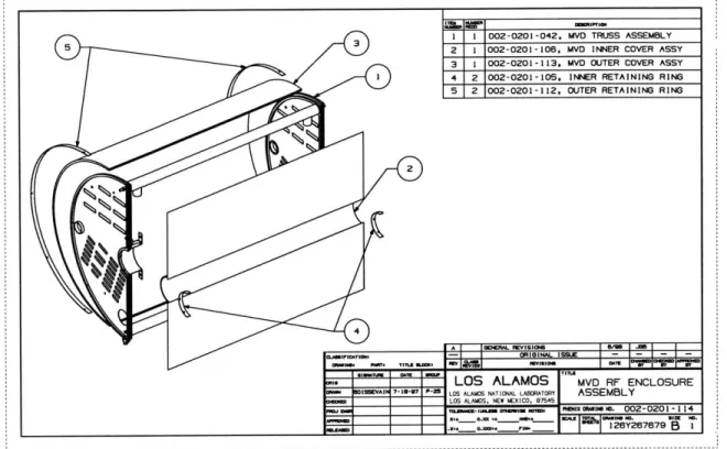
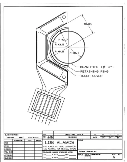
1.5 Overview of the RF Enclosure
The Radio Frequency Enclosure (see Figure 1-4) is an environmental, mechanical, and electronic shield that isolates the MVD from the outside
environment. The main environmental hazards to the MVD's effectiveness are: 1) external RF noise, 2) humidity, 3) high temperatures, and 4) physical damage to the silicon or front-end electronics.
1 1 002-0201-042, MVD TRUSS ASSEMBLY
5 2 1 002-0201-106, MVD IlNER COVER ASSY
3 1 002-0201-113. MVO OUTER COVER ASSY
1 4 2 002-0201-105, lINER RETAINING RING
5 2 002-0201-112, OUTER RETAINING RING
4
A mEWL FFViIO6
-ORIGINAL ISU I
LOS ALAMOS MVD RF ENCLOSURE
IVAI 7-8-W - LOS ALAMOS NATIONAL LABMATORY ASSEMBLY LOS ALAMOS, NEW MEXICO. 187545
InNH WtMIMMI. 002-0201-114
___ ___ 28Y26.7879B
Figure 1-4: Exploded view of the MVD's RF Enclosure
The MVD must be isolated from external RF noise to ensure that the noise radiation is not absorbed by the silicon detectors or readout electronics, which could lead to inaccurate collision vertex and multiplicity findings by the software algorithms. If the silicon support structure (Rohacell foam) absorbs humidity, then it expands, which can cause the central silicon barrel to move and thereby hamper the accuracy of the vertex finding algorithms and perhaps even damage the silicon strip detectors. High temperatures should be avoided in order to keep the silicon detectors running at their optimum efficiency levels as well as to keep the front-end electronics and motherboard electronics from overheating.
In addition to isolation from these environmental hazards, it must also fit into the geometric allowance for the detector, absorb as little of the QGP radiation as possible, be either reusable or replacable, and have minimal cost. In order to
meet these functional requirements, the base design parameters for the RF enclosure are that it: 1) use hemi-cylindrical sheets of Rohacell foam to give it
thermal isolation, strength, and shape while minimizing particle absorption, 2) use Mylar film to provide an air-tight and water-tight seal, and 3) use thin aluminum to provide RF shielding.
Section 2: General notes on RF noise and shielding
2.1 What is RF noise?
Radio frequency noise is electromagnetic interference in the range of radio frequencies. It can be conducted and/or radiated. It is generated by all electrical systems that operate in that range of frequencies, but the particular sources expected to be relevant to the MVD are the electronics associated with the other particle detectors in the PHENIX experimental hall and the particles colliding in the beam pipe. If the amplitude of the RF noise reaching the MVD's sensitive electronics is high, then it can have a significant impact on the ability of the MVD's software to discern the correct multiplicity and vertex of particle collisions.
According to Webster, radio frequencies are electromagnetic wave
frequencies intermediate between audible frequencies and infrared frequencies,5 which have wavelengths roughly between 1 000m and 1 Om; however, in this
document radio frequency noise is considered to be any electromagnetic noise that can affect the MVD. This is because a large majority of the electromagnetic
noise expected to be encountered in the PHENIX experimental hall is RF noise, but due to the impulse-like noise generated by the wave crossings in the beam pipe, there will be some noise that reaches into much higher frequencies.
2.2 The need for shielding
The two ways of avoiding RF noise are to reduce the noise generated and/ or to reduce the noise received. Because the amount of noise generated is uncontrollable in the MVD's particular situation, the focus will be on reducing the amount received. There are three ways to do that: shield the source, shield the receiver, and increase the distance between the source and the receiver. The other particle detectors are responsible for shielding themselves as much as reasonably possible, and because the amount and type of shielding they will
5. Webster's Seventh New Collegiate Dictionary, 1967. G&C Merriam Co., Springfield,
provide is currently unknown, it is assumed that they will not provide enough shielding for the MVD to neglect the noise they transmit. Additionally, the
distances between the sources and the receiver are fixed, because the detector layout in the PHENIX experimental hall has been fixed. Therefore, the MVD must shield its receivers to perform optimally.
2.3 RF shielding
A shield is a partition between two regions of space such that the electric
and magnetic fields of interest are attenuated in passing from one of these regions to the other6. Every electromagnetic wave striking a metallic surface is reflected, transmitted, and absorbed in certain proportions. The shielding efficiency (SE) is the total attenuation measured in decibels of the shield and is the sum of the reflection loss (R), absorption loss (A), and correction term for
multiple reflections loss (C): SE = A + R + C. For most metallic surfaces, the
reflection loss to plane waves is so large that only a small fraction of the energy that strikes the surface will enter the metal.6
The reason for a shield's effectiveness can be explained in terms of the skin effect. For shield thicknesses that reduce any currents induced on one side to zero on the other side, there can be no electromagnetic field on the side with zero current. The current decreases exponentially through the shield thickness as can be seen in Equation 2-1, so it actually will never reach zero no matter how thick the shield is. In Equation 2-1, F is the field intensity at a distance S inches away from the surface, FO is the same field intensity at the surface, p is the resistivity of the material in Q-circular-mils per foot, p is the relative permeability, and f is the frequency in Hertz.
-1.238 ~f
F = Foe - (Eq. 2-1)
Because of this exponential decrease, a perfect shield is theoretically impossible to make. However, at high frequencies, attenuation is rapid and the shield can be
thin and still reduce the transmitted noise to practically undetectable levels.6
There are three idealized mathematical models that can be used to estimate the shielding efficiency of a shield. Each model uses a different
approximation of the noise's wave impedance to arrive at its closed-form solution. The far-field model approximates the noise as plane waves. It is only valid when the noise sources are more than several wavelengths away from the receiver, and
it leads to a fixed wave impedance (Zw) that is the ratio of the electric field intensity to the magnetic field intensity. The electric (or magnetic) field model approximates the noise as a pure electrical (or magnetic) field which assumes that the field is created by a high voltage and low current (or low voltage and high current). It is only valid when the electric (or magnetic) field intensity is "much larger" than the magnetic (or electric) field intensity.
The reflection and absorption losses are functions of the shield material, whether the noise is electric or magnetic, the impedance of the source, the frequency, and to some extent the surface texture7. Because of these
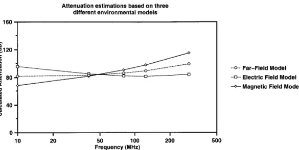
dependences their values differ depending on the field model used. Values for
1 mil thick aluminum shielding 1 m from the source are plotted using the three
different models in Figure 2-1. The original data and derivation of the results can be found in Appendix 1. The equations used to calculate the values for each model were taken from Appendix 6 of the Electrical Interference Handbook1.
7. Ellis, N., 1998. Electrical Interference Handbook, 2nd Ed. Reed Educational and
Attenuation estimations based on three different environmental models 160
'120 -.0
--- Far-Field Model
80 - -- Electric Field Model
-o- Magnetic Field Model
40-0- 1
10 20 50 100 200 500
Frequency (MHz)
Figure 2-1: RF shield attenuation estimations using different source models
The diamonds represent the magnetic field model, the squares represent the electric field model, and the circles represent the far-field model. As can be seen, the electrical field and magnetic field models bound the extremes of the expected attenuation and show opposite dependence on frequency. The far-field
model is approximately the mean of the other models. This is because it assumes that there is both an electric and magnetic field.
As mentioned these calculations are only valid in ideal situations. Any holes, joints, or irregularities decrease the shielding efficiency depending on their dimensions relative to the noise wavelength, but the calculations can be used to provide a rough approximation. When openings are necessary (e.g. for air
cooling purposes) they must be specially designed to minimize their interruption of the induced current flow and strongly attenuate any radiation through them.6
The RF noise environment in the PHENIX experimental hall will have a mix of electrical, magnetic, and far field sources, but their relative proportions have not been determined and the design of the MVD's shield has been completed. The shield was designed so as to attenuate as much RF noise as possible without violating the constraints of size and radiation length.
Section 3: Isolating the MVD from the outside
environment
3.1 Isolation from RF noise
If the RF noise inside the MVD is too high, then the MVD electronics will
not be able to determine if the radiation absorbed by the silicon is from the heavy ion collision or from the RF noise. And if it can't determine which radiation is from the collision, then it cannot determine the multiplicity or vertex.
In order to keep the system signal-to-noise ratio for a single Minimum Ionizing Particle (MIP) signal at greater than the specified 10:1 ratio, it has been determined that the noise inside the MVD must be less than 2500 electrons rms. But how difficult it will be to meet that specification remains to be seen, because the RF noise inside the PHENIX Experimental Hall, where all the PHENIX
detectors are located, is unknown and will not be known until all the detectors are in place and running. Therefore, the MVD should be prepared for the worst case scenario, i.e. RF noise at a large range of frequencies at high amplitudes.
To shield against high frequencies (and short wavelengths) the shielding cannot have large holes as are in a Faraday cage, because the larger the holes the bigger the wavelengths that can seep through them. When extrapolated to the extremely high RF frequencies found in the near square waves that will probably exist in the PHENIX Hall, the shield must be completely solid (no holes) in order to keep out the RF noise. To shield against high amplitudes in lower frequencies, a thicker shield must be used to provide adequate shielding. However, a thick, solid shield adds significantly more mass to the detector than a wire mesh shield, and adding more weight means absorbing more of the QGP radiation.
Two functional requirements conflict with each other: minimizing the absorption of QGP radiation and blocking out external RF noise; therefore, a balance was struck between the shielding provided and the mass added to the detector.
For plane waves, the amount of RF shielding provided per unit thickness decreases exponentially as the thickness of the shielding material is increased6 So the optimal thickness of shielding corresponds to the point at which the exponentially decreasing "thickness versus shielding" curve intersects the
undetermined "thickness versus QGP radiation absorption" curve. The problem is that the "thickness versus shielding" curve cannot be determined until the RF environment in the PHENIX experimental hall has been determined, and that will not be determined until all the detectors are installed and running.
Even if the environment could be determined it is not an issue in any case, because the RF shield design specifies that the shielding must attenuate the noise to the 10:1 signal-to-noise ratio. So the design thickness does not necessarily correspond to the optimal thickness for the shielding concerns, but instead it is determined by the needs of the MVD's silicon, electronics, and software. However, this does not help either, because the thickness needed to meet the 10:1 ratio cannot be determined without a known RF environment.
Because estimating the frequencies and amplitudes of the RF noise to within any useful range is not possible, the RF shield design has been specified with the hope that it will provide adequate attenuation. The design that was chosen is a two-layered aluminum foil shield that completely encloses the MVD. The 0.5mil thick foil layers are separated in the surfaces concentric with the silicon barrel, but make electrical contact at the endcap surfaces and run to ground through a common wire.
3.2 Isolation from air leaks
The MVD needs to be isolated from the outside environment so that the inside temperature and humidity can be controlled. If the temperature rises above
50 Cthen the CMOS chips in the front-end electronics will be damaged, and if the radiation from the heavy ion collisions chronically damages the silicon, then cooling them down will help to decrease the effects of the damage. If the relative
the environment where it operates, then the hygroscopic Rohacell, which holds
the silicon in place, will change shape and decrease the accuracy of the vertex finding algorithms.
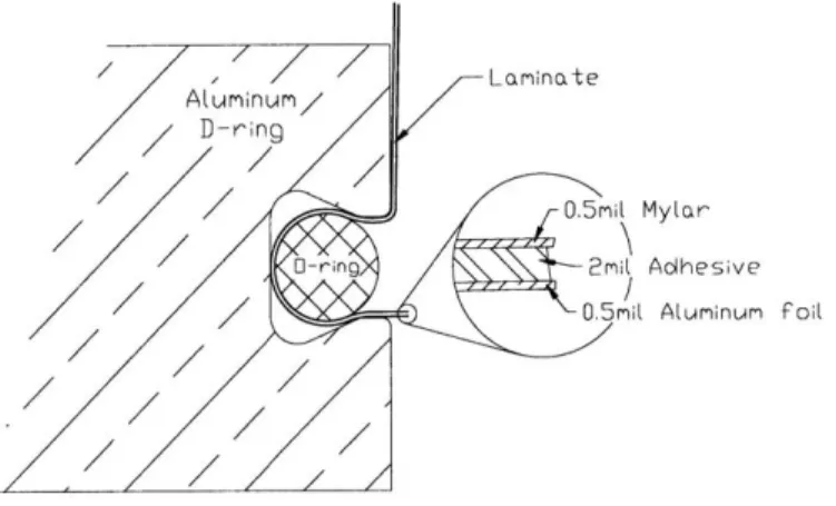
Dupont's Mylar film has been chosen to keep the inner surface of the MVD air-tight. Mylar is a polyester film that provides a barrier to gas and water vapor as well as excellent flex and puncture resistance.8 Each of two 0.5mil thick Mylar sheets is adhered to a 0.5mil thick aluminum foil shield and fit snugly into one of two concentric 0-ring grooves to seal the inner surface (see Figure 6-1).
// Laminate
Aluminum D-ring/
0-ring 2mil Adhesive
O.5mil Aluminum Foil
Figure 3-1: Detail of 0-ring groove and enclosure laminate
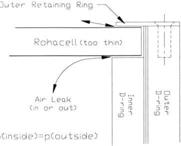
The outer surface is kept air-tight by a 0.25" thick Rohacell cover sandwiched between two layers of 0.5mil thick aluminum foil and held in place by a 1/32" thick aluminum retaining ring (see Figure 6-2).
Ou ter Retaining Ring
RokhazeR
(too thin)
Li
Air Leak (in or out)
p(inside)-p(out side)
(D -3
-1
Figure 3-2: Outer enclosure air leak possible flow path
Each endcap is kept air-tight by two 1/64" thick aluminum endplates positioned between two aluminum D-rings (see Figure 6-3).
Inner and Outer
Endplate Shields 7 ID (0 ID ID Cu 7 7 ID (0 F-1
Figure 3-3: Cross-section detail of D-rings and endplates
There are a few spots on the inner surface that make a completely air-tight and RF-tight seal difficult to accomplish. The corners where the 0-ring grooves of
L T
the D-rings and the seal strips meet are not filleted, and so cause a large amount of strain in the Mylar/ aluminum foil laminate. If the strain exceeds the laminate's
maximum allowable strain, then the laminate will tear and result in an air leak and possibly an RF leak as well. In order to lessen the strain and ensure that no such tears occur, a small amount of tacky putty is placed in the O-ring grooves at the corners. This putty has been found to retain its properties after many weeks of
being exposed to the environment it remains in while inside the RF enclosure. Even if one of the laminates tears, the other laminate in the assembled enclosure will be able to attenuate some of the RF noise and provide the for air seal.
Two other spots that are difficult to seal are the points where the inner Rohacell cover and the inner retaining ring meet the O-ring grooves. These sections are shown in Figure 6-4.
Figure 3-4: Difficult seal points
Again there is a large amount of strain imposed on the laminate at the points where the retaining ring and Rohacell meet the O-ring grooves, and again tears are avoided by putting a small amount of tacky putty in the O-ring groove at that junction in order to ease the strain of the laminates. Cutting the O-rings short of
reaching the end of the groove has also been shown to ease the strain.
3.3 Isolation from temperature gradients
systems, but should the systems fail, the RF enclosure covers will lower the heat transfer rate between the warmer, external environment and the MVD's
environment. This will allow technicians a longer time to repair the cooling system(s).
This lower heat transfer rate is accomplished by the Rohacell foam that provides the structure for the RF shielding foils. Rohacell has a thermal
conductivity of 0.03W/mK. The outer Rohacell cover is 0.25" thick, which gives it a heat transfer resistance value roughly equivalent to one inch of wood. The inner
Rohacell cover is only half as thick at 3mm and therefore has only half of the heat transfer resistance. However, the surface area that is in contact with the external environment is only approximately 1/6th the area of the outer Rohacell cover, so the total heat transferred in via the inner cover is approximately 2.88 times the
heat transferred in via the outer cover assuming the same environmental conditions. All told, the heat transfer through the exposed Rohacell-supported surfaces of a fully assembled MVD is close to the heat transfer through a 23"x23"xO.25" sheet of plywood.
Section 4: Building the Inner RF Enclosure
4.1 Thermoforming properties of Rohacell IG-71
Rohacell is a closed-cell rigid expanded plastic material, or more
accurately, a polymethacrylimide rigid foam (PMI). It has excellent mechanical properties, high dimensional stability under heat, solvent resistance, and a low coefficient of heat conductivity. Its strength, modulus of elasticity, and modulus of shear are not exceeded by any other foamed plastic having the same density.9
See Table 4-1 for comparison of Rohacell's properties with other materials.
Table 4-1: Physical Properties of Structural Support Materials
Density Tensile Compressive Elastic Thermal Radiation
3 Strength Strength Modulus Conductivity Length
(MPa) (MPa) (GPa) (W/mK) (m)
Rohacell 75 2.8 1.5 0.092 0.03 5.45 IG-71 a Pine 300 -900 40 -190 30-80 9-16 0.120 -Woodb Poly- 60 1.6 0.9 0.033 0.03 styrened a. b. c. d.
Rohacell Technical Information pamphlet, page 5 CRC Mechanical Engineer's Handbook
2.51 book
Rohacell Technical Information pamphlet, pages 12-14
Rohacell is fabricated in flat sheet form in various thicknesses and sizes, but the RF enclosure requires that the Rohacell be in a hemi-cylindrical shape. There are two processes that will obtain the correct shape: 1) thermoforming or 2) machining layers that have been glued together. The least expensive and least wasteful of material is the thermoforming procedure.
Thermoforming Rohacell is a process which raises the temperature above
the dimensional stability point and starts breaking the chemical bonds that hold the Rohacell together. While the material is above that temperature, it can be formed into just about any shape so long as the bending radius is more than twice that of the thickness9. When the material is cooled down to below the
dimensional stability point, the structural bonds reform, and the material retains the new shape with approximately the original physical properties.
During the summer of 1997, tests were performed to accurately determine the relationships between the thermoforming temperature, time, pressure, and method to help find an acceptable and reliable procedure which could be used to thermoform the RF enclosure. The PHENIX technical document1 0,
"Thermoforming Rohacell for the MVD's Radio Frequency Enclosure", was written to summarize the setup, testing procedures, data collected, and conclusions drawn from the tests, and it has been included in Appendix 2.
The results of these tests indicated that the amount of springback, i.e. the tendency of the Rohacell to return to its pre-thermoformed shape, can be reduced
by lowering the cooling rate. The results also indicated that higher pressure of the
thermoforming fixture on the Rohacell during the cool down process helps to reduce the amount of size growth.
Size growth occurs when the Rohacell reaches the foaming temperature10, i.e. the temperature at which the chemical bonds are weak enough that the
pressure of the gas inside the foam cells causes the cells to expand.
Unfortunately the foaming temperature is only approximately 10 C above the forming temperature, so it is difficult to avoid foaming altogether, but the size growth can be controlled by the amount of pressure applied through the thermoforming fixture.
4.2 The Inner RF Enclosure Thermoforming Procedure
1. ROHACELL TO BE SHAPED TO RADIUS nisVI /7lo
SHOWN IN 180IC OVEN. I3MMAI N/3 2 LOS ALAMOS MVD ENCLOSURE
CAM~~ LOS ALAMOS NATIONAL LABORATORY I NNER COVER
2. MACHINE TO FINAL LENGTH AND HEIGHT LOS ALAMOS, NEW MXICO. 87,545 0 114
700=- V , N S FinQ 002-00-0
E - 0. .- Qmr 12BY287879B7
Figure 4-1: The inner RF Rohacell cover
For the particular application of thermoforming Rohacell for the inner structural piece of the RF enclosure (see Figure 4-1), the tolerances on its final shape are tight. As can be seen in Figure 4-2 below, the MVD is designed so that there is only a 5.4mm gap between the surface of the Rohacell and the 1 mm thick beryllium beam pipe, and only a 3.35mm gap between the other Rohacell surface and the inner barrel of silicon strip detectors. For the integrity of the experiment and the MVD, no part of the MVD is allowed to touch the beam pipe, and the MVD
management does not want any part of the inner RF enclosure to touch the silicon strip detectors for fear that the contact might affect the detectors' operation. Therefore, even though the curved edges of the inner Rohacell cover are fixed into position, any springback must be avoided to keep the free section of the inner Rohacell's straight edge from bowing out to touch the silicon strip detectors.
Figure 4-2: Clearances around the inner Rohacell cover
However, these tolerances can be met. In addition to the 1997 tests, some tests were completed in June of 1998 in cooperation with the Rohacell
manufacturer's pamphlet. The results helped to show that the required tolerances for the inner hemi-cylinder of Rohacell can be met using the thermoforming materials and procedure delineated in the PHENIX technical documentl1,
"Fabricating, Assembling, and Installing the Inner Radio Frequency Enclosure of the Multiplicity Vertex Detector", which has been included as Appendix 3.
The springback and thickness growth values for the two 1998 tests utilizing the procedure found to produce the best results are tabulated in Table 4-2 below.
Table 4-2: Results of Tests Using the Final Thermoforming Procedure Avg. % change Avg. % change Total amount intruded Avg. % safety in radius in thickness into safety gaps (mm) gaps intruded on
Test #6 0 8.56 0.13 3.10
Test #7 0 7.18 0.11 2.60
The average percent change in radius is the measure of the springback converted into useful dimensions. It was measured by comparing the cooled Rohacell's radius with the radius of the forming fixture. Zero percent springback means that the thermoformed Rohacell has the exact radius that it should have, and therefore there should be no bowing in the straight edge that could touch the silicon strips. The average percent change in thickness was determined using eight measurements along the edges of the cooled Rohacell. The safety gaps are imaginary volumes that occupy the space that starts at the surfaces of the
Rohacell cover and extend out 1/3 of the distance between them and the silicon strip detectors or them and the beam pipe. The safety gap between the Rohacell and the silicon strips is 1.1mm, and the safety gap between the Rohacell and the beam pipe is 1.8mm. Ideally, the Rohacell will never extend past the safety gap, but for safety's sake there is still 2/3 of the entire gap space left to expand into should the inner enclosure need it. The total amount intruded into the safety gap and average percent of the safety gap that was intruded on show that the chosen thermoforming procedure leaves a fair amount of room for error.
This thermoforming procedure was chosen not only because of its size growth and springback results, but also for its ease of production. Other procedures were tested and gave acceptable results, but this procedure
minimizes the fabrication time (5 total hours; about 0.5 man hours) in drying out the Rohacell, preheating the thermoforming fixture, and cooling down the
4.3 The Inner RF Enclosure Machining Procedure
The springback and thickness growth tolerances are met by the thermoforming procedure, but the tolerances on the length and width
specifications are met by machining the Rohacell after it is thermoformed. If the length of the Rohacell is not controlled, then the force put on the curved ends by the strut assembly of the MVD could cause the entire shield to buckle, which could in turn cause the inner RF enclosure to come in contact with the silicon strip detectors.
Here, machining is used not to refer to the use of a mill or lathe, but rather to a more general use of shop tools in a shop environment. More specifically, the
materials needed to machine the Rohacell to the required tolerances are: the thermoforming fixture, low grit sandpaper, an X-acto knife, and a measuring tape. The entire procedure is delineated in the inner RF enclosure technical document already mentioned, Appendix 3. Using the procedure, the Rohacell can be
machined to specifications in a reliable and efficient manner. For an experienced worker, the entire process takes approximately 20 minutes. The procedure is
better done in-house rather than out-sourcing to a machine shop, because it uses the thermoforming fixture as a precise guide for straightness in cutting and as a
length model for cutting to the exact arc length needed. The thermoforming fixture also serves as an excellent device for holding the Rohacell in the desired
position without crushing it.
4.4 The Inner RF Enclosure Assembly Procedure
The inner enclosure assembly procedure, also described in Appendix 3, involves: 1) adhering the RF shielding foils to Mylar foils to increase the tensile and puncture strength and to make the enclosure more air tight, 2) cutting the laminates to the correct dimensions, 3) adhering the foil laminates to themselves, and 4) adhering the laminates subassembly and another Mylar foil to the Rohacell for structural strength. The procedure takes a fair amount of time and experience to perform correctly, but it results in a robust, durable, effective RF shield.
The first step is adhering the shielding foils to the Mylar foils. The 0.5mil
sheets of aluminum foil that provide most of the shielding effect have an adequate tensile strength but are very easy to puncture or tear, and because any tears have
large stress concentration factors associated with them, they will propagate through the entire sheet once they have been started. But if a thin sheet of Mylar is adhered, then the resulting laminate is fairly robust and durable.
Also, the Mylar provides a tighter air seal than the aluminum foil, and
therefore is needed especially at the edges that are used in conjuction with the 0-rings. The adhesive used to hold the foils together is Dielectric Polymers' NT 988-2 dry transfer adhesive. It is a 988-2mil thick adhesive that is delivered in large rolls. Each layer of the adhesive is separated by an extremely non-stick, silicon coated paper. This paper is one of the only materials that the adhesive does not violently stick to, which makes handling the adhesive difficult.
The addition of the Mylar was a significant change to the original RF shielding design. It added several new layers of material to the design, and this added material also added mass, and that mass did not provide very effective RF shielding per unit mass, and so was avoided as much as possible.
However, because the aluminum foil was extremely hard to protect during the assembly and installation procedures, and because the added layers only added 0.06% of a radiation length to the detector, the design changes were implemented.
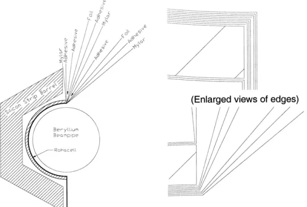
The completed assembly is comprised of ten layers: three layers of 0.5mil thick Mylar, four layers of 2mil thick NT 988-2, two layers of 0.5mil thick aluminum foil, and one layer of 125mil thick Rohacell foam (see Figure 4-3).
V,
>01
<
(Enlarged views of edges)
Ber yLiurn Be mppe
RohaceL
Figure 4-3: Layers of the inner RF enclosure
The second step in the assembly process is cutting the laminates to the correct dimensions. This is a fairly simple step, because the dimensions have fairly loose tolerances. The laminates are constructed to have plenty of extra area to account for any mistakes in the first step made around the edges. This extra will be cut off when the laminates are installed into the rest of the MVD. The only
portion of the laminates that must be cut carefully is the area that will be adhered to the Rohacell cover. This area has a tolerance of about 1/16", which is easily attainable using the aluminum cutting template so that there is no measuring needed.
The third step is adhering the laminates together. To increase electrical shielding, the two aluminum foils must be electrically separated. Mylar is a
polyester, which has a high volume resistivity (1018A cm), and therefore makes a
good enough insulator to separate the foils. The laminates are held together with the NT 988-2 dry transfer adhesive, and are only attached together on the
minimize the mass added as well as reducing the assembly and installation times. The fourth and final step is adhering the laminates subassembly to the Rohacell cover and then adhering a final sheet of Mylar to the uncovered side of the Rohacell. The laminates are adhered to the surface of the Rohacell that is nearest to the beam pipe and on the outside of the MVD. This outer surface is used instead of the inner surface in order to make the assembly procedure easier, reduce the chance of the Rohacell absorbing water from the air, and to give the MVD a uniform look. The additional Mylar sheet is adhered to the other side of the Rohacell to ensure that humidity from the air inside the MVD is not absorbed and to ensure that no dust particles from the Rohacell are blown around inside the MVD, which could interfere with the operation of the silicon strip detectors.
Again the NT 988-2 dry transfer adhesive is used to adhere the laminates subassembly and the additional Mylar sheet to the Rohacell. The NT 988-2 is the
best adhesive found for the job, and one of the only adhesives found that will stick to the Rohacell at all.
It takes approximately 2.5 hours to complete the assembly procedure for the inner RF enclosure for one half of the MVD. The ten layers give a total thickness of approximately 0.136". If only conduction resistance is considered, the total heat transfer resistance through the surface enclosing the beam pipe is approximately 64W/K. The total radiation length is approximately 0.18%.
4.5 The Inner RF Enclosure Installation Procedure
The inner RF enclosure is one of the last components to be integrated into the MVD. It should be installed after all the structural components, electronics, and outer RF enclosure have been installed, but before all cables and hoses have been attached. After it is installed, there is no way for the electronics inside to be modified without first removing the inner enclosure, and the inner enclosure cannot be removed without destroying it. However, because the fabrication procedure is relatively inexpensive and a new enclosure can be made in a matter of a few hours, the decision of whether to repair or modify any of the electronics is not influenced by the removal of the enclosure.
Because it is installed after all the electronics, the procedure for installation must be very reliable and have an extremely small possibility of damaging the already installed components. However, this constraint is not easily met due to the force required to lay the O-rings into their respective grooves. Depending on how the MVD is held in place, the large amount of force could torque the MVD so much that it overcomes the opposing torque due to gravity, resulting in a crash of dire consequences. Therefore, a fixture is being designed that will securely hold the MVD in a fixed position so that there is no chance of an accident.
The installation procedure for the inner enclosure is documented in Appendix 3. It has two main parts: 1) attaching the hemi-cylindrical Rohacell section to the adapter cuffs of the aluminum D-rings and 2) installing the foil laminates in the O-ring grooves and trimming off the extra. With the experience of just a few installation trials, the whole process takes on the order of one hour to complete, but it requires two people during the O-ring installation steps.
The first part is straightforward and simple. The Rohacell with attached laminates must be adhered to the half-MVD's aluminum frame, which is a subassembly that consists of four aluminum D-rings (so named for their shape), four thin aluminum endplate shields, two aluminum adapter cuffs, and two hollow, cylindrical, aluminum struts. In order to precisely locate the inner Rohacell cover the two adapter cuffs are precisely and permanently fixed to the D-rings, and then the inner RF enclosure assembly is adhered to the cuffs and pressure is applied
by four aluminum retaining rings to hold them in place.
The next step is to push the foil laminates into the O-ring grooves. This is most easily accomplished with the help of a spline tool. A spline tool is a tool specifically made for this purpose. It is a handle with one roller on each end. One roller helps to crease the screen or foil into the groove, and the other is made to press the O-ring into the groove without allowing it to slide around. The spline tool that was used was very generic, and therefore had to be modified to the correct dimensions using a lathe. The thickness constraint was determined by the size of the O-ring grooves, and the wheels were machined with a small radius so that they do not buckle under the force.
Figure 4-4: Cracked Buna-N 0-ring material in inner enclosure mock-up
The O-ring material used is urethane. The original material was Buna-N (nitrile), which is a much more universally used and cheaper O-ring, but after little more than a month of being installed with the foil laminates in the D-rings in a mock-up of the MVD frame, it was found that the Buna-N was severely cracking. This can be seen in Figure 4-4 above. One manufacturer and one distributor of
0-rings were contacted for advice and suggestions. One suggestion was that the ozone in the air was causing the cracking, but that potential explanation was quickly ruled out. A test was performed to determine the cause of the Buna-N's cracking as well as to test another O-ring material, urethane, for the same
behavior. The Buna-N was subjected to several independent combinations of the environmental elements that were present while it was inside the O-ring grooves. The elements combined were tension, contact with aluminum foil, contact with
Mylar, and contact with the NT 988-2 adhesive. Also, the urethane was put under tension and in contact with the adhesive. The tests were conducted over three months.
Only the O-ring strips that were put under tension and in contact with Mylar and those that were under tension and in contact with the dry adhesive showed the cracking that the O-ring strips in the MVD mock-up showed. Based on those observations, more precisely controlled tests would have to be performed to have meaningful results. No decisive conclusions were drawn about the cause of the
cracking, but since the urethane showed no signs of cracking, the decision was made to use urethane instead of taking a chance with Buna-N.
Once the 0-rings are in place, the only thing left to do is cut off the extra laminate strips. This is an easy step, but care should be taken, especially at the corners, not to tear or puncture the laminates in any vital area. If any tears or holes are made in the vital areas of the aluminum foil during any step of the
installation, then the enclosure should be scrapped and a new enclosure installed. Many inner enclosures will need to be fabricated during the lifetime of the MVD. At least one needs to be installed during testing of the MVD at the Los Alamos facilities, several others need to be shipped separately to the PHENIX experimental hall, one needs to be used during the MVD's tests at Brookhaven, one needs to be installed before the MVD is installed in PHENIX, and then at least one is needed for every time the MVD is repaired or modified after that. Since there is no disadvantage (besides losing storage space) to fabricating several
extra inner enclosures before they are needed, the same person should make several within a short time period to ensure accuracy and uniformity between the enclosures.
Section 5: Building the Outer RF Enclosure
5.1 The Outer RF Enclosure Thermoforming Procedure
The thermoforming procedure for the outer enclosure is very similar to the procedure for the inner enclosure. The Rohacell must be cut to the approximate size needed and then dried out. Then it can be aligned in the thermoforming fixture, which will hold it in its post-thermoforming shape while it is thermoformed and then cooled.
It is possible to hold the cold Rohacell in its post-thermoforming shape because the final radius of curvature is large enough that bending a flat sheet to that radius will not impose a stress higher than its maximum tensile or
compressive yield stress. The curvature of the thermoforming fixture is circular, but the curvature of the bending Rohacell is the same as that of a cantilevered beam and varies proportionally to the cube of the distance from the fixed end. When the Rohacell is forced around the fixture, it touches the fixture where the natural cantilevered beam deflection equals the deflection of the fixture's
curvature. The intersection of the curves in Figure 5-1 shows the point where the deflections are equal.
Thermoforming fixture curvature vs. Natural Beam bending curvature 0 -0.05 - - - - ---0 .1 - -- - - - -.0 - 0 .15 - - - -- -y=sqrt(r2 2 )-r fixture
- - - y=-x. natural bend
- 0 .2 - - - -- - - -- -
--0.25-.
0 0.05 0.1 0.15 0 .2 0.25 Distance from fixed end(m)
Figure 5-1: Thermoforming fixture vs. Rohacell bending curvatures
When it touches the fixture, the working length of the Rohacell is shortened by the arc length of the fixture to that point. By shortening the working length, the moment on the beam is decreased, which keeps the stresses in the Rohacell from going above its yield stress.
The thermoforming fixture was designed to provide a generally uniform heat flux into and out of the Rohacell. It consists of a 0.0625" thick sheet of aluminum, four 0.25" thick aluminum ribs which hold the sheet in the correct shape, and several small parts which help to rigidly hold the fixture together. The
ribs were machined by clamping four 0.25" aluminum plates together on a rotating chuck that was fixed to the milling bed. The chuck was offset so that the milling bit cut all the aluminum plates to the same correct radius as the chuck was rotated, and holes were drilled through all four plates so that struts could be used to offset the plates from each other without changing their relative axial position.
After the Rohacell is placed into the forming fixture, the temperature of the fixture is increased to and kept at the thermoforming temperature (approximately
temperature is slowly decreased until all the bonds have reformed. At that point the Rohacell can be removed and put in storage until it needs to be cut to the exact dimensions. This procedure is detailed in Appendix 4: Fabricating, Assembling, and Installing the Outer Radio Frequency Enclosure of the Multiplicity Vertex Detector12
The tolerances for the thickness growth and springback of the outer
Rohacell cover are determined by the strain imposed on the shielding foil covering the Rohacell and by the distance between the inner Rohacell cover and the silicon strip detectors, respectively. A conservative estimate shows that the thickness growth cannot be larger than the twice the initial thickness of the Rohacell cover multiplied by the ultimate tensile stress of the foil divided by the Young's modulus of the RF shielding foil (see Equation 5-1 below), or else the foil will tear and produce a hole that high frequency RF radiation can leak into. Calculation of the maximum tolerable thickness growth gives a result of 2.7mils for a maximum final thickness of 0.2527".
Thickness Growth=tf - t E = E = ;t - t< 2iu (Eq. 5-1)
The maximum springback growth is more difficult to determine analytically, because the cylindrical shape leads to a non-obvious working length, the end constraints are not easily defined, and there are two thin aluminum strips installed into the straight edge the have grooves for the 0-rings that help resist any
springback. The maximum springback also depends on the amount of tension used to install the inner enclosure's foil laminates into the 0-ring grooves in the straight edge of the outer enclosure. Because of the difficulty in solving a detailed model, a very conservative estimate was made that the springback should be less than 1/8th of the distance between the edge of the inner Rohacell cover and the
edge of the silicon strip detectors, or less than 0.035".
Although the calculations would be difficult, the idea is not hard to grasp. If the springback of the outer Rohacell cover is negative, i.e. the straight edge bends
in towards the central axis, then there is probably not going to be a problem. But if
the Rohacell springback is positive and during the inner enclosure installation the Rohacell is force into a straight shape, then the springback will pull on the
laminate foil layers of the inner RF enclosure. If the force pulling on the laminates is strong enough, then the laminates will pull the inner Rohacell cover into the silicon strip detectors, which must be avoided.
If the installation procedure for the inner enclosure installation is followed
precisely, then the laminate foils will be cut to match the curvature of any
springback, and there will be very little tension on the laminates. However, if any force is put on the outer enclosure to straighten out the springback, or if tension is put on the laminates when they are installed into the O-ring grooves, then that force and/or tension will remain after the installation. This in turn will pull on the
inner Rohacell cover, which is approximately eight times weaker than the outer RF cover due to its smaller thickness. Because the inner cover is approximately eight times weaker, the pulling force will impart a deflection of its straight edge that will be approximately eight times larger than the outer enclosure's deflection, so any small force on the outer Rohacell cover will cause a large springback in the inner
Rohacell cover (see Equation 5-2 below).
houter = 2hinner -1 > louter = 81inner * 8outer = 88inner (Eq. 5-2)
Tests were done during the fall of 1998 to determine the parameters for a thermoforming procedure that would meet the required tolerances for springback
and thickness growth. Out of the eight outer Rohacell covers fabricated, two exceeded a positive average springback of more than 0.035" (they were 0.05" and
0.11"). For thickness growth, one of the eight covers had a positive average
growth over 2.7mils (5.5mils). Barring those test specimens the procedures tested gave results within the defined tolerances, and the parameters chosen for
the final procedure are listed in Table 5-1 below.
Table 5-1: Properties of outer enclosure thermoforming tests
Drying Drying Forming Forming Cooling Average Average
Time Temp Time Temp Time Growth Springback
180min 120 C 30min 185 C 45min -2.2% -3.6mm
5.2 The Outer RF Enclosure Machining Procedure
Once the outer RF enclosure is thermoformed within the specified
tolerances, it must be cut to exact dimensions. This involves three steps: cutting the length to specification, cutting the width to specification, and then milling out the seal strip grooves. The length is the distance around the curved portion of the Rohacell, and it must be cut to within approximately 1 mm of its nominal value at the corner edges to ensure that the O-ring grooves flow smoothly from the D-rings to the seal strips and back into the other set of D-rings. The width is the distance from one of the curved edges to the other, and it must be cut to greater than
28.81" but less than 29.06" in order to keep the enclosure correctly situated on the
D-rings. The seal strip grooves are grooves that have to be milled into the straight edges of the Rohacell for the aluminum seal strips. The seal strips are machined to very tight tolerances, and the Rohacell must be milled so that the seal strips fit snugly into the grooves without putting too much force on the thin Rohacell edges. The exact dimensions of the outer enclosure are shown in Figure 5-2 below.
129 .125 137 _ R 11.42 mATERIALs ROHA *REOU1RED: 4 .061 137 w~I~-I --29.06 '.B33 REF I I I GP'P. " '"'"t 11'V.- I-I I
r- LOS ALAMOS MVD ENCLOSURE
OA( ,i LOS ALAMOS NAIJONAL LABORATORY OUTER COVER
MAI "LOS ALAMOS, NEW MEXICO. 8745
*ooa1,.. 002ir0Z07 6 109
Figure 5-2: The outer Rohacell cover
Even though the tolerance of the length is fairly tight, it can still be met using a razor blade and fixtures. The first fixture is simply a precise mock-up of the rings and strut assembly. With the Rohacell positioned correctly in the
D-rings, marks can be made which precisely show what the width of the finished outer enclosure should be. The marks can then be used in conjuction with
another fixture to precisely cut the Rohacell to the width marked. This process is neither difficult nor time consuming. It should take an experienced person about
30 minutes to cut one half-cover to specification.
The width tolerance is loose, and can also be met using a razor blade, sandpaper, and a fixture. Because the Rohacell is already cut to the correct length, it can be aligned by those edges in the correct orientation. Using the fixture to hold it in place, the Rohacell can be rough cut to the correct width with a razor blade, and then sandpaper used to bring it to the exact dimension.
Once the length and the width are cut, a seal strip groove needs to be milled into both straight edges of the Rohacell cover. The groove thickness must be machined to within a few mils of the nominal dimensions so that the seal strips
22
CELL 1G71
1 - 1
will fit snugly; therefore, a mill must be used. And because the length of the cover is almost 30", a mill with a long travel distance bed must be used. The milling bit's
axis should be horizontal instead of vertical, because the shape of the Rohacell
cover requires that if a vertical axis mill was used, then an intricate fixture that was extremely well stabilized would have to be designed and constructed and a mill with a large vertical travel as well as horizontal travel would have to be used.
Upon procurement of the use of a horizontal axis mill, a machining fixture was designed and fabricated to hold the Rohacell in place on the milling bed (see
Figure 5-3a, b, and c below).
Outer Enclosure Machining Fixture
For millng seal strip groove in Rohacett cover
386 tapped hoP (through) 2 places
1T
6666IhI36.0E-H
2
1
36 13/32 ha (thr gh); 2 plce Oter Machining Fixture Assembly 6.91 unecn6 u r R co vertop lte (mc-eas
botton half or ... chnin fixtur
1 625
4.0 0.25
-0.875
Figure 5-3b: Enlarged view of top plate (C-beam)
Nn
P
tu
eM
r
re
bly
outer Rohacell cover
top half of machining fixture
bottom half of machining fixture
Figure 5-3c: The outer cover machining fixture assembly
The design consists of two main parts, the base plate and a top plate. The base plate is flat and rigid to provide a reference surface for the mill to align with. The top plate is a C-beam (half of an I-beam), and provides a high vertical stiffness so that the force of the bolts used to clamp the top plate to the base plate is
0.28
Mxc
Ai
Ass
distributed along the entire width of the Rohacell. The design minimizes the complexity with just four parts (top plate, base plate, and two bolts) and thereby
minimized the expense of time and money to fabricate it.
The milling procedure requires that a vertical reference point be found once
by touching the base plate to the milling bit at several points along its width. Then
the Rohacell sheet is bolted in place in the machining fixture and the base plate is set to the correct vertical position and the milling bit is run along the width of the Rohacell. Because the bit used to mill out the foam is not exactly the same diameter as the desired thickness of the seal strip groove, the bed's vertical position is then changed to mill out the extra foam, and the bit is run back along the width for the final cut. After one groove is milled, then the Rohacell is taken out of the fixture, flipped over, and placed back into the fixture to mill out the other groove.
The milling machine used to machine the Rohacell cover test specimens was fairly old and not very accurate. As the bed travelled horizontally from one extreme to the other, the vertical position of the bed relative to the milling bit was shown to change by approximately 1 Omils. There was also another vertical error that did not show up on the digital positioning readout and was not consistent over the tests. It varied from no error to approximately 40mils. It did, however, seem to
be consistent while the Rohacell was bolted in place, so that the groove
maintained the desired thickness. Due to time constraints, the exact reason for the error was not thoroughly investigated; however, it was reasoned and tested that even the largest error that was produced could be tolerated and did not significantly effect the ability of the enclosure to provide RF shielding, humidity and temperature isolation, structural protection, or a secure hold on the seal strips.
Once the milling is finished, the handler should be extremely careful with it, and avoid touching the grooved, straight edges. Each groove makes two thin "lips" of Rohacell, which have a length of 132 mils and vary in thickness from 28mils to 88mils depending on the amount of vertical error in the positioning of the mill relative to the milling bit. These lips are very fragile and could easily be