2D-3D Rigid-Body Registration of X-Ray
Flouroscopy and CT Images
by
Lilla Z6llei
Submitted to the Department of Electrical Engineering and Computer
Science
in partial fulfillment of the requirements for the degree of
Masters in Engineering in Electrical Engineering and Computer
Science
at the
MASSACHUSETTS INSTITUTE OF TECHNOLOGY
August 2001
@
Lilla Z611ei, MMI. All rights reserved.
The author hereby grants to MIT permission to reproduce and
distribute publicly paper and electronic copies of this thesis ASSAHEfuwTTS NTITUrE
in
whole or in part.
OF TECHNOLOGYNov 0 1 2001
LIBRARIES
A uthor ...
...
Department of Electrical Enineering and Computer Science
August 10, 2001
Certified by
...
W. Eric L. Grimson
Bernard Gordon Chair of Medical Engineering and Professor of
Computer Science and)Engineering, MIT Al Lab
"Thesis- Supervisor
Certified by.
Williiam M. -Wells III.
Research Scientist, MIT Al Lab
Assitant Professor of Radiology,
Harvard Medical School pn-Biiham an*-V
ens'Hospital
uervisor
Accepted by
Arthur C. Smith
Chairman, Departmental Committee on Graduate Students
2D-3D Rigid-Body Registration of X-Ray Flouroscopy and
CT Images
by
Lilla Z611ei
Submitted to the Department of Electrical Engineering and Computer Science on August 10, 2001, in partial fulfillment of the
requirements for the degree of
Masters in Engineering in Electrical Engineering and Computer Science
Abstract
The registration of pre-operative volumetric datasets to intra-operative two-dimensional images provides an improved way of verifying patient position and medical instrument location. In applications from orthopedics to neurosurgery, it has a great value in maintaining up-to-date information about changes due to intervention. We propose a mutual information-based registration algorithm to establish the proper alignment. For optimization purposes, we compare the performance of the non-gradient Powell method and two slightly different versions of a stochastic gradient ascent strategy: one using a sparsely sampled histogramming approach and the other Parzen windowing to carry out probability density approximation.
Our main contribution lies in adopting the stochastic approximation scheme suc-cessfully applied in 3D-3D registration problems to the 2D-3D scenario, which obvi-ates the need for the generation of full DRRs at each iteration of pose optimization. This facilitates a considerable savings in computation expense. We also introduce a new probability density estimator for image intensities via sparse histogramming, derive gradient estimates for the density measures required by the maximization pro-cedure and introduce the framework for a multiresolution strategy to the problem. Registration results are presented on fluoroscopy and CT datasets of a plastic pelvis and a real skull, and on a high-resolution CT-derived simulated dataset of a real skull, a plastic skull, a plastic pelvis and a plastic lumbar spine segment.
Thesis Supervisor: W. Eric L. Grimson
Title: Bernard Gordon Chair of Medical Engineering and Professor of Computer Science and Engineering, MIT Al Lab
Thesis Supervisor: William M. Wells III. Title: Research Scientist, MIT Al Lab Assitant Professor of Radiology,
Acknowledgments
First and foremost, I would like to say thank you to my thesis supervisors Prof. Eric Grimson and Prof. Sandy Wells. Both of them greatly supported me in achieving my goals throughout these two years and were there to talk to me whenever I had ques-tions or doubts. Prof. Grimson, thank you for your knowledgeable advice regarding research issues, class work and summer employment. Sandy, thank you for being so patient with me and being open for a discussion almost any time. I learned a lot while working with you!
My special thanks go to my third (and unofficial) thesis supervisor, Eric Cosman,
the author of my precious Thesis Prep Talk. I really appreciated all of our valuable conversations throughout the past year and thanks for keeping me inspired even through a nice and sunny summer. Notice, I managed not to forget how much I
prefer neon to sunlight!
I sincerely appreciate all the help that I got from our collaborators at the SPL,
the Brigham and from the ERC group. In specific, I would like to mention the people who helped me obtaining the majority of my 2D and 3D acquisitions: Ron Kikinis, Dr Alexander Norbash, Peter Ratiu, Russ Taylor, Tina Kapur and Branislav Jaramaz.
Thank you to all the people in the Al Lab for all your valuable suggestions and advice and special THANKS to those who took time to read through my paper and/or thesis drafts: Lauren, Raquel, Kinh and Dave. Lily, thanks for the Canny edge-detection code!
Tina, I would also like to express how greatly I appreciate your never-ending en-thusiasm for research and the trust that you invested in me since the first day I got to MIT. I have truly enjoyed collaborating with you!
And at last but definitely not at least I would like to express my appreciation for the constant encouragement that came from my parents and my bother even if the former have been thousands of miles away... Anyu, Apu es Pisti! Vgteleniil kszon6m
This work was supported by the Whiteman Fellowship and the NSF ERC grant
Contents
1 Introduction 15 1.1 2D-3D Registration . . . . 15 1.2 Medical Applications . . . . 17 1.2.1 3D Roadmapping . . . . 17 1.2.2 Orthopedics . . . . 19 1.3 Problem Statement . . . . 20 1.4 Thesis Outline . . . . 202 Background and Technical Issues 23 2.1 2D-3D Rigid-Body Registration . . . . 23
2.1.1 Medical Image Modalities . . . . 25
2.1.2 Digitally Reconstructed Radiographs . . . . 26
2.1.3 Similarity Measures . . . . 30 2.1.4 Optimization . . . . 32 2.1.5 Number of Views . . . . 33 2.1.6 Transformation Representation . . . . 34 2.1.7 Transformation Parameterization . . . . 36 2.1.8 Other Notations . . . . 38
2.2 Outline of Our Registration Approach . . . . 38
2.3 Sum m ary . . . . 40
3 The Registration Algorithm 41 3.1 The Transformation Parameter . . . . 41
3.2 The Objective Function . . . .
3.2.1 Definition of MI . . . .
3.2.2 MI in the Registration Problem
3.3 Probability Density Estimation . . . . 3.3.1 Parzen Windowing . . . .
3.3.2 Histogramming . . . . 3.4 The Optimization Procedures . . . . . 3.4.1 Powell's Method . . . . 3.4.2 Gradient Ascent Strategy . . . 3.4.3 Defining the Update Terms
3.5 Gradient-based Update Calculations
3.5.1 Partial Derivatives of Density Estimators
3.5.2 Partial Derivatives of Volume Intensities wrt T
3.6 Sum m ary . . . .
4 Experimental Results
4.1 Probing Experiments . . . . 4.2 Summary of the Registration Algorithm . . . .
4.2.1 Step 1: Preprocessing . . . . 4.2.2 Step 2: Initialization . . . . 4.2.3 Step 3: Optimization Loop . . . . 4.3 Registration Results . . . . 4.3.1 Registration Error Evaluation . . . . 4.3.2 Objective Function Evaluation . . . . 4.4 CT-DRR Experiments . . . . 4.4.1 CT-DRR Registration . . . . 4.4.2 Multiresolution Approach . . . .
4.4.3 Robustness, Size of Attraction Basin . . . . . 4.4.4 Accuracy Testing . . . . 4.4.5 Convergence Pattern 80 . 43 44 45 46 47 47 48 48 49 50 51 52 55 58 59 59 62 63 63 64 66 66 68 68 68 72 75 76 . .
4.4.6 Registration Parameter Settings . . . . 4.5 CT-Fluoroscopy Experiments . . . . 4.5.1 Experiments with X-Ray Images of Gage's Skull . . . 4.5.2 Experiments with Fluoroscopy of the Phantom Pelvis 4.6 Sum m ary . . . .
5 Concluding Remarks
5.1 Sum m ary . . . .
5.1.1 Controlled Experiments . . . .
5.1.2 CT - X-ray Registration . . . .
5.2 Future Research Questions and Ideas . . . .
5.2.1 Coupling Segmentation and Registration . . . .
5.2.2 View and Number of Fluoroscopic Acquisitions . . 5.2.3 Defining Automatic Stopping Criterion for Gradient
tion Protocols . . . . 5.2.4 Truncation/Limited Field of View . . . .
5.2.5 Distortion Effects & Dewarping . . . .
5.2.6 Histogram Characteristics . . . .
5.2.7 Code Optimization . . . .
5.2.8 Im proving M I . . . .
6 APPENDIX
6.1 Small Angle Rotation. . . . . .. . . . .
6.2 The Story of Phineas Gage. . .. . . . .
9 82 83 85 92 92 97 Optimiza-97 98 99 99 99 101 101 102 102 102 103 103 105 105 106
List of Figures
2-1 Lateral and AP acquisitions of X-ray fluoroscopic images of the pelvis phantom . . . . . 26
2-2 Orthogonal slices of a head CT acquisition: axial, sagittal and coronal v iew s . . . . 26
2-3 CT-derived DRR images produced by the ray-casting algorithm . . . 28
2-4 CT-derived DRR images produced by the voxel-projection algorithm 30 2-5 The transformation parameter T which relates the coordinate frames
of the imaging environment and the data volume; T = D, o R o Dd. . 34
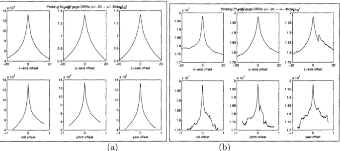
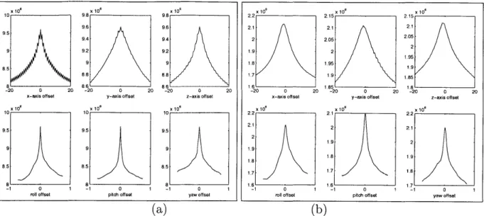
4-1 Results of two probing experiments evaluating (a) mutual information and (b) pattern intensity on the skull dataset. Displacement range of
+/ - 20 (mm) and rotational range of - +/ - 45 (deg) were specified. 61
4-2 Results of two probing experiments evaluating a cost function on (a) the original and (b) the downsampled and smoothed version of the same phantom pelvis dataset. Displacement range of
+/
- 20 (mm) and rotational range of -+/
- 45 (deg) were specified. . . . . 624-3 Single-view simulated fluoroscopic images from the controlled experi-m ents. . . . . 70
4-4 Registration results of a phantom pelvis controlled experiment with the Reg-Pow method: contours of registration results are overlaid on the observed DRR images . . . . 81
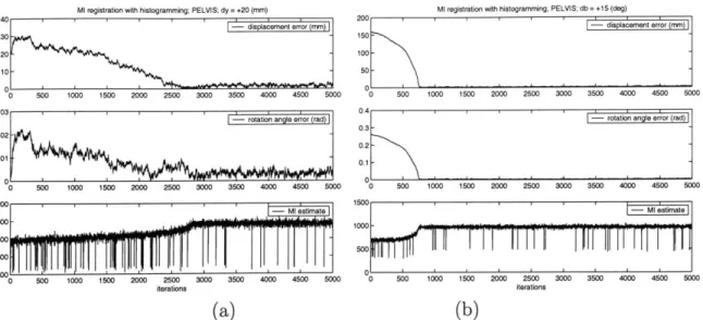
4-5 Sample output from a controlled set of Reg-Hi experiments. Dataset: plastic pelvis. Initial offsets: (a) y = 20 (mm) and (b) 3 = 15 (deg).
Plots display the magnitude of displacement error, rotation angle and the MI estimate at each iteration. . . . . 82
4-6 Real X-ray fluoroscopy of the phantom pelvis and real X-ray images of Phineas Gage's skull . . . . 84 4-7 Error distribution based upon the results of 30 experiments with
ran-dom initial offset on a given interval. Row 1 displays plots with respect to error terms de and re while row 2 demonstrates errors in Dd and R 88
4-8 Error distribution based upon the results of 30 experiments with ran-dom initial offset on a given interval. Row 1 displays plots with respect to error terms de and re while row 2 demonstrates errors in Dd and R 89
4-9 Registration results of an experiment on real X-ray and CT of the Gage's skull dataset using the Reg-Pz method. . . . . 90
4-10 Registration results of an experiment on real X-ray and CT of the Gage's skull dataset using the Reg-Pz method. Contours of the DRR images created by the output of the registration algorithm are overlaid on the original fluoro images . . . . 91
4-11 Registration results of an experiment on real X-ray and CT of the Gage's skull dataset using the Reg-Pow method. Contours of the DRR images created by the output of the registration algorithm are overlaid on the original fluoro images . . . . 93
4-12 Registration results of an experiment on real X-ray fluoroscopy and CT of the phantom pelvis dataset using the Reg-Pow method. Contours of the DRR images created by the output of the registration algorithm are overlaid on the original fluoro images. . . . . 94 4-13 Registration results of an experiment on real X-ray fluoroscopy and
CT of the phantom pelvis dataset using the Reg-Hi method. Contours
of the DRR images created by the output of the registration algorithm are overlaid on the original fluoro images. . . . . 95
List of Tables
4.1 CT dataset specifications; smi: smoothed volume on hierarchy level
2; sm2: smoothed volume on hierarchy level 3; sm3: smoothed volume on hierarchy level 4 . . . . 69
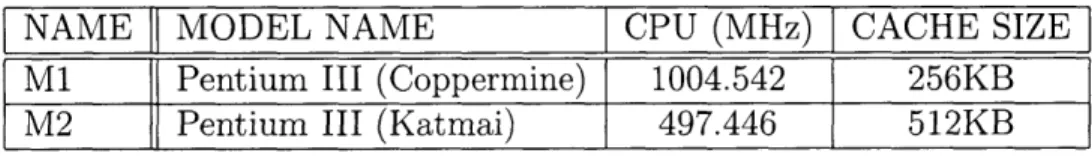
4.2 Computing resources - machine specifications. . . . . 71
4.3 Timing measurements to contrast registration running time on different hierarchical levels. . . . . 74 4.4 Controlled, registration accuracy tests using the Reg-Hi method; No
hierarchy; . . . . 76
4.5 Registration results of methods Reg-Pz, Reg-Hi and Reg-Pow on con-trolled experiments of a phantom pelvis and a real skull . . . . 78
4.6 Error measurements for the X-ray fluoroscopy and CT registration ex-periments on the Gage skull dataset . . . . 87
Chapter 1
Introduction
1.1
2D-3D Registration
Recently, there has been a growing number of medical experts who advocate a mini-mally invasive approach to surgery. Their aim is to reduce the physical stress applied to the human body due to medical treatment/procedures and also to reduce treatment costs, for example, by minimizing the size and number of incisions. Unfortunately, in comparison to open procedures, these approaches restrict the surgeon's view of the anatomy. This leads to an increasing need for advanced imaging techniques that would help them not only with diagnosis, but also with planning and guiding inter-ventions.
Pre-operative images provide an excellent source of detail about the anatomy in question. The widely used three-dimensional image modalities such as Magnetic Resonance Imaging (MRI) and Computed Tomography (CT) contain high resolution information about the imaged body part. Other imaging techniques such as Positron Emission Tomography (PET) and Functional MRI (fMRI) complement that knowl-edge with metabolic and functional information. All these datasets can greatly assist in establishing diagnosis and planning procedures pre-operatively or evaluating an intervention post-operatively. The same set of images can be conveniently utilized in surgery as well. However, they have the drawback that they may not completely
reflect the surgical situation, since they are static.
In some applications it is important to use intra-operative images to follow the
changes caused by the procedure or to visualize the location of a tool. In the operating
room or interventional suite, it is mostly 2D images that are available to record details about the current anatomical state. X-ray, X-ray fluoroscopy and portal images are all good examples of image modalities used for this purpose. Two-dimensional acqui-sitions are often taken instead of volumetric datasets because of timing,
radiation-related and technological arguments. First, acquiring several 3D volumetric images
during a procedure takes too long to make it practical compared to 2D imaging. Sec-ond, the radiation dose to both the patient and the doctor is reduced if only image slices are recorded rather than all the projections needed to reconstruct a 3D volume. Third, by using only 2D images, it is sufficient to have simpler imaging equipment in
the operating suites.
Unfortunately, 2D images lack significant information that is present in the 3D
modalities. Hence, in order to relate the changes recorded by the 2D modalities to the detailed 3D model, medical experts need to fuse the information from the pre-operative and intra-operative images mentally, which can be a challenging task. Therefore, it is useful to find a way to both automate that procedure and to make it reliable.
The combination of pre-operative and intra-operative images conveys the most information if the components are properly aligned in space. To achieve this it is necessary to determine their relative position and orientation. The procedure that identifies a geometrical transformation that aligns two datasets, or in other words locates one of them in the coordinate system of the other, is called registration. There already exist several techniques that can perform this task either semi- or
fully-automatically. Matching, for example, different types of MRI with each other
or with CT datasets is routinely done at numerous medical institutions. Most of these applications operate on images of the same dimensionality, aligning inputs from either 2D or 3D. Could we, nevertheless, align images with different dimensionality
and complement the information from high-resolution pre-operative datasets with the more up-to-date, intra-procedural images? To achieve this goal, not only would we have to account for the different representations of a particular anatomical structure in the multimodal inputs, but we would also need to process information represented in different spaces. Additionally, as the registration results are expected during the medical procedure, the computation time would also be constrained. In a nutshell, these are the main challenges that one needs to address when solving the 2D-3D registration task. In our work, we present a solution to these problems and discuss the performance behavior of our registration framework.
1.2
Medical Applications
In this section, we give some specific examples of medical applications that could benefit from a reliable (and efficient) solution to the 2D-3D registration problem. They belong to the field of Image Guided Surgery (IGS). Their main objective is to introduce highly accurate pre-operative information about the examined anatomy into the operating room (where normally only lower dimensional images can be acquired) and help the execution of interventions carefully planned prior to the procedure by fusing the more detailed pre-operative with the more current intra-operative images.
1.2.1
3D Roadmapping
There exist a number of serious illnesses which can treated by the use of catheters that are maneuvered into the blood vessels of the brain. These include aneurysms
and arteriovenous malformations.
Traditionally, X-ray fluoroscopy has been widely used in these cranio-catheter procedures. There is a currently existing procedure called 2D roadmapping in which doctors follow the path of a catheter in the patient's body with the help of dynamic intra-operative 2D imaging. The procedure takes place in a special fluoroscopy suite. Prior to the intervention, opaque contrast material is injected into the patient, and a 2D acquisition is obtained. The resulting image shows vessels with high contrast
because of the injected contrast agents. This type of data is used pre-operatively for diagnosis and planning, and it is also often acquired at the beginning of a procedure to serve as a reference set during the procedure. When the contrast agent is no longer present in the blood, dynamic fluoro images are acquired to follow the changes due to the intervention and to record the most current state of the treated body part. These are then subtracted from the pre-operative static image. As a result the vessels (of high contrast in the operative data) and the catheter (not present at all in the pre-operative data) are the only structures highlighted. Continuing this process allows the physician to obtain information about the actual location and the movement of the catheter.
The main disadvantage of this method lies in having only a static 2D reference image highlighting the vessels. It is not rare that cranio-catheter procedures take more than 5 hours. During such a long time it is difficult to prevent any patient movement. Misalignment between the pre-operative image and the intra-procedural ones is inevitable. When that happens re-injection of the contrast agent is necessary for obtaining another static reference image and the intervention is halted.
In the future, the drawbacks of the 2D roadmapping method might be overcome by using a 3D dataset as the reference from which synthetic 2D images can be generated as needed'.
Prior to the surgery, when the initial dose of contrast agent is injected, it requires a 3D volume rather than 2D images to be taken. During the procedure, when the dynamic fluoro images are obtained, they are compared to simulated projection im-ages created from the 3D dataset. In this way, if the patient moves, it is only the parameters that describe the patient position and orientation in the imaging model that have to be modified in order to have the simulated and intra-procedural images line up again. These parameters are the ones that a 2D-3D registration algorithm would compute.
'This project has been jointly proposed by Alexander M. Norbash, MD (Department of Radiology, Brigham and Women's Hospital and Prof. William Wells (Artificial Intelligence Laboratory, MIT).
1.2.2
Orthopedics
Metastatic Bone Cancer
Another application is related to an orthopedics procedure, the treatment of metastatic cancer in the bones. The task here is to remove localized lesions from particular
lo-cations of the bones. Again, the treatment plan can be thoroughly designed prior to the operation using 3D CT volumes with high information content, but during the intervention, guidance and verification is only practical by making use of intra-operative images. Utilizing both of the two data sources requires the alignment of the intra-operative and pre-operative datasets.
Total Hip Replacement
Hip joint replacement surgery has several uses for 2D-3D registration. One is implant-ing an acetabular cup into the pelvic bone durimplant-ing total hip replacement procedures. In order to verify the correct position and orientation of the metal cup before the op-eration terminates 2D images are acquired. These need to be related to the 3D model of the anatomy. Another use concerns cases in revision surgery. Such a procedure is necessary if, following a total hip replacement procedure, the acetabular cup gets mislocated or gets deattached from the pelvis.
These orthopedics applications are currently pursued by the HipNav project at
CMU and researchers at Johns Hopkins University.
Spine Procedures
Spine procedures are another very large application area for IGS, since back problems are very common, and the potential complications of damage to the spinal cord are devastating. Planning may effectively use pre-operative CT, while the interventions may be most practically guided by the use of C-arm X-ray equipment. One example procedure is vertebroplasty, which is the reinforcement of a failing vertebra by the placement of cement. Other applications include the placement of pedicle screws as components of stabilization hardware.
1.3
Problem Statement
The goal of the project described in this document is to register pre-operative volumet-ric data to intra-procedural 2D images. We are particularly interested in examining the problem of aligning 3D CT volumes to corresponding X-ray fluoroscopy. As a single 2D image, in practice, does not convey sufficient information about the spatial location of the imaged object, we require two projection images to achieve our task. We assume that the two imaging views are related by a known transformation, hence it is necessary to recover the required transformation with respect to only one of them. (This is a realistic assumption as biplanar images are often taken by rotating the imaging source by a pre-specified angle around one of the imaging axis. Also, biplanar acquisitions are considered to be standards in cranio-catheter applications.) In solving the proposed problem, our main challenges lie in identifying a similarity measure, or objective function, that can quantify the quality of the alignment between the images and defining a procedure to modify and refine current estimates of the problem parameters in a way that the similarity score is optimized.
An additional primary focus of this effort is finding 2D-3D alignment methods which have computational complexity that is compatible with the time constraints implied by the interventional applications.
Experimentally, we aim to demonstrate the performance characteristics of our reg-istration algorithm on a wide variety of datasets. The collection includes fluoroscopy and CT datasets of a plastic pelvis and a real skull and also a high-resolution CT-derived dataset of a real and plastic skull, a plastic pelvis and a plastic lumbar spine segment.
1.4
Thesis Outline
In Chapter 2, we introduce the problem of 2D-3D registration in a more thorough manner. We present the technical difficulties involved in the analysis and comparison of the multimodal and multidimensional datasets. We then summarize a handful
of approaches that have already presented promising results in this area. We also introduce some frequently-used medical image modalities, describe some objective functions and some fast methods that simulate X-ray generation; which is a subtask of some registration methods. In Chapter 3, we focus on the computational details of our own approach. We describe the particular choices made when designing the components of our algorithm, we demonstrate the data structures used to encode the transformation variables and provide an in-depth derivation of the most important formulas used in the implementation. In Chapter 4, registration experiments are described using both synthetic and real datasets as well as detailed analysis of their results. The thesis concludes with Chapter 5, which summarizes the project and our contributions. Finally we describe some related future research ideas that we would like to investigate. In the Appendix, the reader may find a precise derivation of a particular mathematical formula and also a summary of the fascinating case of Phineas Gage, whose skull was used in our experiments.
Chapter 2
Background and Technical Issues
Introduction
In this chapter, we give a general introduction to the 2D-3D rigid-body registration problem applied specifically to medical modalities. We present a concise summary of research studies that have been applied to the problem while outlining a highly selec-tive set of objecselec-tive functions, optimization procedures and medical image modalities that are most frequently used in medical image processing. We also describe a fast technique that produces simulated projection images, called digitally reconstructed radiographs, as this technique was crucial in speeding up and monitoring our regis-tration procedure. Then we introduce a new approach that we used to address the
2D-3D registration task.
2.1
2D-3D Rigid-Body Registration
Registering pre-operative datasets to images acquired intra-operatively can provide up-to-date information at the treatment site, guiding surgery or other interventions. When using different image modalities, information invisible in one of them can be incorporated into the other. Three-dimensional intra-procedural image acquisition is uncommon - typically only two-dimensional datasets can be obtained for such purposes. Although these images lack the spatial detail of volumetric data, they have
the advantages of faster acquisition time and potentially reduced amount of radiation exposure to both patients and doctors. Ideally, one can recover the advantages of the volumetric data by aligning the intra-operative 2D images with pre-operative volumes. However, not only do we have to focus on solving the multi-dimensional registration problem, but the algorithm running time should also be kept reasonable. If the alignment results cannot be produced well within the time-limits of an intervention, the algorithm cannot be used.
The majority of the medical applications for the proposed kind of registration task has emerged in the field of radiology. Alignment information is crucial in planning, guidance and treatment procedures. More specifically, the medical community has expressed interest in applying the 2D-3D alignment results in the following applica-tion areas: placement of pedicle screws in spine surgery [5, 6], aortic endoprostheses in transfemoral endovascular aneurysm management [7], verifying patient setup ac-curacy for radiotherapy and acetabular implant position in case of total hip replace-ment [1, 2, 11], displaying surgical instrureplace-ments in the pre-operative CT volume [5], projecting important anatomical structures visible in CT onto 2D acquisitions and confirmation of depth electroencephalogram electrode position [33].
Our collaborators1, in specific, are interested in applying the 2D-3D registration in the field of orthopedics and neuroradiology. Two of the major projects that of interest are head catheter tracking in case of cranio-catheter procedures and monitor-ing acetabular cup insertion durmonitor-ing total hip replacement surgery. (A more detailed description of these and other procedures can be found in Chapter 1.) Therefore, the experimental dataset that we have acquired is mostly images of the skull and the pelvis.
'Alexander M. Norbash, MD (Department of Radiology, Brigham and Women's Hospital) and the Engineering Research Center (ERC) group including collaborators from CMU, Johns Hopkins University and MIT
2.1.1
Medical Image Modalities
The most commonly used 2D medical image modalities for the 2D-3D alignment task have been portal images and X-ray fluoroscopy (fluoro). Portal images are used in radiation treatment procedures. Their creation employs high-energy treatment radi-ation beams instead of low-energy imaging radiradi-ation, hence they could be considered byproducts of a procedure and their quality is extremely poor - they are of low resolution and they have low contrast. Research studies involving this modality use various segmentation techniques prior to or simultaneously with the registration pro-cedure [1, 2, 30] in order to identify key structures in the portal images. Otherwise the individual intensity values have not been found to be sufficiently informative to describe the imaged anatomy.
Fluoroscopic images, on the other hand, reveal much more detail about the exam-ined anatomy. They are taken by X-ray machines and are created by short wavelength energy. Fluoro images best visualize bony structures of the anatomy (Figure 2-1), as it is the bony tissues that absorb the most amount of radiation in the human body. The major disadvantage of this modality stems from the fact that without correction, its geometric accuracy degrades due to pincushion and radial distortion effects in cur-rent equipment. (Distortions of this sort are not a problem with the newer generation solid-state detectors.)
Among the 3D image modalities, Computed Tomography (CT) has been most widely considered for the registration task. CT images are created by assimilating multiple X-ray acquisitions. The X-ray machine rotates around the patient's body and at pre-specified angles shoots X-ray beams through the imaged object. The reconstructed images represent the absorption rate due to the intervening tissues
called the Hounsfield number.
On the other end, the imaging plate records the absorption rate of different tissue types which quantities are referred to as Hounsfield numbers. The tomographic data acquisition is conventionally modeled by the Radon Transform and reconstructed according to the Filtered Backprojection algorithm. Distortion problems are usually
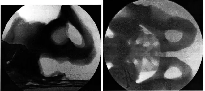
Figure 2-1: Lateral and AP acquisitions of X-ray fluoroscopic images of the pelvis phantom.
not of major concern in case of this modality. Figure 2-2 shows three orthogonal slices of a real head CT acquisition.
Figure 2-2: Orthogonal slices of a head CT acquisition: axial, sagittal and coronal views
2.1.2
Digitally Reconstructed Radiographs
In our application, we focus on fusing CT and X-ray fluoroscopy images. One of the key challenges when attacking the 2D-3D registration problem is the need for an appropriate way to compare input images that are of different dimensionalities. The
most common approach is to simulate one of the modalities given the other dataset and an estimate about their relative spatial relationship, so that the images can be compared in the same space. Then the transformation estimate can be updated to maximize an alignment score according to some similarity measure.
Reconstructing the 3D volume from 2D images is one alternative, but it requires numerous projection acquisitions and large computation time. It is more feasible to simulate 2D images from the 3D volume. Most existing applications follow this
approach.
Ray-Casting
Simulated projection images, that are to model the production of X-ray acquisitions from volumetric CT are called Digitally Reconstructed Radiographs (DRRs). These images are traditionally formed by implementing the so-called ray-casting algorithm which we briefly summarize. Rays are first constructed between points of the imaging plane and the imaging source. Then the individual intensity values of the DRR images are computed by summing up the attenuation coefficients associated with each volume element (voxel) along a particular ray. An example of a DRR image created according to this algorithm is shown in Fig. 2-3.
Although producing high-quality results, this procedure can be quite inefficient for our purposes. As it must visit every voxel while computing the projection image, it tends to be extremely time-consuming. The creation of just one projection slice can take up to 100 seconds on a fast 1000 MHz machine. If we want to introduce a registration algorithm for interventional use, which task might require the creation
of hundreds of DRRs as intermediate steps, we need to find alternative methods to approximate the 2D projections.
The speed limitations of the ray-casting algorithm are partly due to the size of the volumetric datasets. The majority of the CT volumes that we analyzed had dimensions of (512x512x200). (See a more detailed summary of the specifications of our datasets in Table 4.1 of Chapter 4). But the other part of the problem stems from the fact that if we closely follow the ray-casting algorithm, the data voxels are
(a) (b)
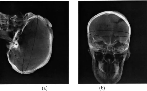
Figure 2-3: CT-derived DRR images produced by the ray-casting algorithm
not accessed in an optimal way. As DRR-creation is a significant component of the registration application, several research studies have concentrated on defining more practical methods for their computation.
One way to address the problem of handling large volumes is to somehow restrict the size of the 3D datasets to be analyzed. In [3], the authors introduce a focused registration technique. The region of interest in the CT acquisition is segmented out prior to the intervention (e.g., the image of a vertebra) and the alignment algorithm is applied only with respect to that sub-entity. The same issue may also be effectively addressed by the application of a multiresolution approach, where it is a downsampled and smoothed version of the input images that are first aligned[18, 15, 16]. (The hierarchical approach not only decreases the computational time, but also increases the robustness of the algorithm. A more detailed description of the hierarchical
approach can be found in Chapter 4, where we present our experimental results.)
Voxel-Projection
To approach the problem from an algorithmic development point of view, it is useful to invent new approximation methods for constructing the DRRs. One such
-dure, which we used in our registration experiments, is called voxel-projection [14]. The main idea behind this new method is the attempt to maximally optimize memory accesses while processing the input datasets. Instead of carrying out the calculations following the layout of the DRR intensities to be determined in memory (and travers-ing the CT volume in a random manner), it accesses the volume elements in the order in which they are stored. First the algorithm estimates how much influence an indi-vidual volume element would contribute to elements of the DRR image. Then, after projecting the voxel centers onto the imaging plane, a smoothing function assures that the resulting image is not corrupted by banded intensities. That could happen due to lack of interpolation and due to ignoring the impact of a voxel on neighboring pixels. In our application, we achieved some improvement in the quality of the DRR images
by increasing the minimal size of the smoothing kernel originally determined [14]. To
compare the image quality of radiographs produced by the ray-casting method and the voxel-projection technique, compare Fig. 2-3 and Fig. 2-4, which display DRR images derived from the same CT volume with the two different algorithms.
Careful examination of Fig. 2-3 and Fig. 2-4 reveals that the two DRR-production algorithms result in images that are very similar. The main criticism against the outputs of the fast, voxel-projection technique could be that its images are not as smooth as that of the traditional procedure. Some intensity banding is visible on the more uniformly colored regions of its images.
The voxel-projection strategy has led to a speedup of factor 6, especially when relatively lower resolution projection images are sufficient.
Other DRR Techniques
Other approaches that also improve the computational burden of the ray-casting procedure include shear-warp factorization [32, 8 and the pre-computation of line integrals with the construction of a new data structure called Transgraph2 [12].
2
The name Transgraph is based on Lumigraph from the field of Computer Graphics.
(a) (b)
Figure 2-4: CT-derived DRR images produced by the voxel-projection algorithm
The main idea behind the latter comes from the field of computer graphics, and is referred to as view-based rendering. It allows for fast computation of the DRR values and easy differentiation of the function generating them. Interpolating the densely sampled pre-computed line integrals proves to be more efficient than im-plementing the ray-casting technique. However, that strategy imposes a significant pre-computational/pre-processing step.
2.1.3
Similarity Measures
In many registration systems, the quality of alignment is scored by objective functions. Common registration methods can be grouped into two major categories based upon the nature of the similarity measure that they apply: they can be classified as feature-or intensity-based.
Feature-based Techniques
Feature-based approaches rely on the presence and identification of natural landmarks or fiducial markers in the input datasets in order to determine the best alignment. It is necessary to segment the most significant features in both of the input images and the
matching criterion is then optimized with respect to them. Contour- and point-based techniques [5, 6, 10, 41] are examples of this strategy, as well as registration methods that compare medialness properties of segmented anatomies
[30].
Others carry out a minimax entropy strategy [1, 2] executing simultaneous registration and segmenta-tion steps. Although the reduced number of features to be registered could provide great computational speedup (after the segmentation procedure is completed), major drawbacks of these methods lie in the need to carefully plan the image acquisition protocols in advance and the need for potentially re-scanning the patient if the diag-nostic images do not contain the fiducials, the assumption that most of the fiducial markers can be located in all of the analyzed inputs, the inconvenience of planting artificial markers on the patient and the dependence on the segmentation procedure that can potentially introduce (additional) errors. These solutions might also require some level of user interaction, which generally is not desirable throughout medical procedures.Intensity-based Measures
Intensity-based measures operate on the pixel or voxel intensities directly. They calculate various statistics using the raw intensity values of the inputs which are then compared in the images to be aligned. Though the number of points to be registered is much greater than in the case of the feature-based methods, no feature extraction step is required.
An extensive study of intensity-based similarity measures applied specifically to
2D-3D applications has evaluated the performance of six different objective functions
in matching X-ray fluoroscopy and CT images [3]. The imaged organ was a phan-tom spine, and it was only a user-defined small region of interest (e.g., an individual vertebra) that was registered at a time. The objective functions considered by the authors were: normalized cross-correlation [33], entropy of the difference image [9], pattern intensity [6], mutual information [20, 15], gradient correlation [34, 33] and gradient difference [3]. After a careful registration study (using fiducial markers to ensure accuracy), the authors ranked these measures based upon their accuracy and
robustness. They found that the best objective functions for the examined multi-modal registration task are pattern intensity and gradient difference. These measures proved to be the most robust with respect to the (simulated) presence of soft tis-sue and of a surgical instrument appearing only on one of the modalities. Both of these objective functions were implemented to use the whole input image in order to
evaluate the current quality of alignment.
The information theoretic measure of mutual information (MI) performed poorly in these experiments. It did not handle partial occlusions and truncations well and its performance further deteriorated when soft tissue was present. The study found two possible explanations for the failures of this similarity measure that has at the same time been very successful in the 3D-3D domain. First, MI is stated to require a large set of samples to obtain a good probability density estimate for the underlying entropy calculations. Although that is given in the 3D-3D registration problems, for the 2D-3D application that was not true. We say more about this aspect of their results later, in Chapter 3. Second, the authors claimed that as the search space of MI is much larger than what the problem requires, it is more difficult to recover the required parameters in it. (MI does not make the assumption that the two compared
modalities are related via a linear function, it assumes a broader statistical relation-ship between the analyzed variables.)
Other intensity-based measures that have also been introduced for solving the CT-DRR registration task are absolute correlation coefficient [34], cross correlation and magnitude of scalar product of gradient [33] and a second order estimation to mutual information that aims to incorporate spatial information into its MI-measure
[31]. The pattern intensity measure was also successfully applied in an MR-derived
DRR and CT registration problem [14].
2.1.4 Optimization
Provided we have a suitable similarity function, the best alignment parameters can be located with the help of an optimization procedure. Such a protocol is responsible
for modifying the current parameter estimates in a way that the similarity function eventually takes on its (local) extremum. In this work, we assume that the similarity measure is a reward and not a cost function. Hence the perfect/ideal alignment is assigned the highest score and an optimization procedure aims to maximize the objective function.
There are two major types of strategies that perform the maximization task: non-gradient and gradient methods. Non-gradient strategies execute a local search in the parameter space by evaluating the objective function at different locations according to a pattern, while gradient procedures use the gradient information to indicate the direction to the desired extremum. The former strategy might be easier to implement as it requires only the evaluation of the objective function and no additional computations to derive the consecutive search directions. However, the latter could potentially be much faster as its search is specifically guided towards the extremum. Among the non-gradient methods, we found that the Powell method
[34],
the downhill simplex strategy[14]
and an iterative optimization of individual transformation parameters (often called as "coordinate ascent" method) [5, 3] are the most popular. Among the gradient-based approaches, it is the Levenberg-Marquardt-type strategies [11, 29] and the hill-climbing (gradient ascent) approach [42, 15] that dominate.2.1.5
Number of Views
In our experiments, examining only a single 2D image is not sufficient to robustly re-cover all registration parameters required to properly position the examined anatomy in the 3D world. While we can quite accurately recover in-plane rotation and displace-ment transformations, it is difficult to determine any out-of-plane transformations. In order to establish all of the transformation components with a desired level of cer-tainty, it has proven advantageous to use two or more 2D acquisitions [2, 12, 14, 35] for the proposed alignment problem.
2.1.6
Transformation Representation
Our task when attacking the 2D-3D registration problem is to return a geomet-ric transformation that best specifies the position and orientation of the examined anatomy at the time of obtaining the 2D projection images. In other words, we want to find a way to align the imaging and the world coordinate systems or to deter-mine the correspondence between the intra-operative imaging environment and the coordinates of the pre-operative volumetric data (Fig. 2-5).
We focus on fusing CT and biplanar X-ray fluoroscopy images. In that specific case, the emphasis is on registering bony structures, since both modalities best visual-ize such information. Characterizing the rigid movement of bones implies six degrees of freedom. One 3D parameter specifies orientation, the other provides displacement information. No other transformation, such as shearing or scaling is allowed. If we also wished to align finer details, such as soft tissues, we would define higher-dimensional transformations. Data coordin T ate system Imaging coordinate system
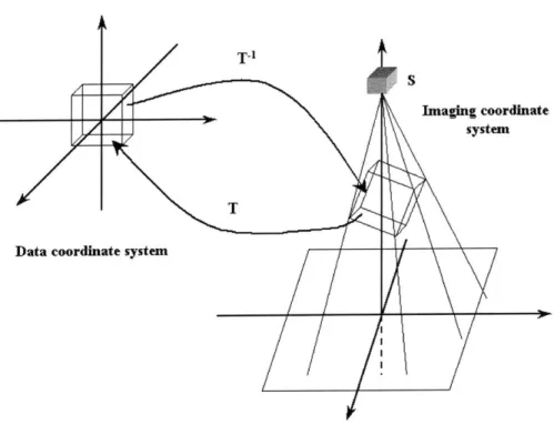
Figure 2-5: The transformation parameter T which relates the coordinate frames of the imaging environment and the data volume; T = D, o R o Dd.
Throughout this thesis, we denote the transformation that aligns the two coor-dinate systems by transformation T. In order to obtain a better intuition for what movement T represents, we decompose it into a collection of sub-transforms. When operating on data-points of the 3D volume, it is most natural to have all rotations happen around the center of the volume. Hence, if the data is not centered in its own coordinate system, a displacement operator needs to be applied. This displacement operator is constant for a given registration task as it only depends on the specifica-tions of the input volumetric dataset. Following the displacement, it is a rotational step and a translation in the oriented system that ensure the desired alignment. If we denote these operations by Bc,
Q
and B respectively (the underscore c notation emphasizes the fact that the associated variable refers to a constant), then a trans-formation G from data coordinates to the imaging environment could be composed asG= BoQoB.
As mentioned above, though, we are interested in computing the inverse of this transform, G-1, which converts image coordinates into data coordinates. Hence, we
can write transformation T:
T = G-' = B; o
Q
o B-1. (2.1)In order to simplify our notation, we introduce new transformation variables for the inverse operations
Dc Bc-1, R
Q
1 , and Dd = B 1 ,and thus modify the way we express T as:
T = G-' = B;1 o
Q-'o
B1 = D o R o Dd. (2.2)The objective of the registration algorithm is to recover the non-constant
nents of T as accurately as possible. In Chapter 3, where we iteratively estimate the best parameters to provide the ideal alignment between the input images, the nature of the above decomposition plays an important role. (Note that we keep the same notation introduced for the decomposition of T throughout the rest of this document.)
2.1.7
Transformation Parameterization
For representing all six degrees of freedom of the rigid-body transformation, we use a new data structure. It is called pose and its name stems from the two notions that it describes: position and orientation. Given a pose parameter we can easily identify both its rotational and displacement components. As the rotational component is not linear in its parameters, the order of applying the transformation elements is essential; reversing them could produce a significantly different transformation. We use the usual convention of applying rotation first and then displacement. Therefore, if pose S were composed of rotational and displacement components (r, d), when applied to a coordinate point x, the resulting point could be written as
x' = S(r, d, x) = r(x) + d.
The composition of two pose transformations is not commutative. Given two poses
Si(ri, di) and S2(r2, d2), we have
S3(r3, d3, x) = S2(r2, d2, Si(ri, di, x)) = S2 o S1(ri, di, x)= r2(rl(x)) + r2(di) + d2,
so r3 = r2 o r1 and d3 = r2(di) + d2.
That is to say, in the case of two consecutive transformations, the rotational elements are composed and the total displacement results from the rotated version of the first translation added to the second translation.
If the pose parameter only had a displacement component, we would write
and if it only involved rotation, then the transformed point would become
X' = S(r, x) = r(x).
It is important to remember the above conventions, as in Chapter 3, when deriving the partial derivatives of the objective function with respect to the transformation
parameters, we heavily rely on them.
There exists several ways to encode the transformation parameters that need to be recovered. The displacement part of T can be conveniently represented in a 3D vector format, however, the rotation parameter can be formulated in several different ways. Just to name a few of the options, we could use: roll-pitch-yaw; Z-Y-X Euler angles; Z-Y-Z Euler angles; equivalent angle-axis, orthonormal matrices and quaternions [23, 36]. We decided to represent our rotation operators as unit quaternions. This representation was appropriate for our needs as the quaternion encoding is easy to formulate and the composition of rotation operators (which occurs very frequently in our code) becomes a vector multiplication in that space. One way to define a quaternion is by a four-dimensional vector whose elements encode the
rotational information as follows:
q = cos , sin 0 . (2.3)
In Definition (2.3), 0 refers to the angle of rotation around the unit-length axis w.
Quaternions
are appropriate measures if we want to define a metric on the space of rotations and they allow a uniform sampling of the rotation space [36].We also use the equivalent angle-axis notation when illustrating the derivation of one of the update terms of the gradient ascent procedure in Chapter 3. In that case, if we represent the rotation transform with vector k, the magnitude of k determines the angle of rotation and its direction stands for the axis of rotation.
2.1.8
Other Notations
To follow the conventional notation in the medical imaging literature, we write U to denote the reference image and V to express the intensity values of the moving or floating images. In our case, U stands for the X-ray fluoroscopy acquisitions while V stands for the simulated radiographs. As the DRRs are constructed from the CT volume given a transformation estimate T, when we indicate the images that we compare, we use the notation (U(x); V(T(x))) to explicitly emphasize that dependence.
2.2
Outline of Our Registration Approach
Goal
The aim of our study is the registration of biplanar 2D X-ray fluoroscopic images to a corresponding 3D CT dataset. The geometry of the imaging environment is assumed to be known, so the location of the two imaging sources for the 2D acquisitions is taken to be fixed. By updating our initial best estimate of the transformation components, we aim to make the CT-derived simulated projection images (DRRs) best approximate the observed fluoro acquisitions.
The Choice of Similarity Measure
Our choice of similarity measure depended on the examined image modalities, prior knowledge about features and possible distortions in the images to be registered, speed requirements (whether the registration needed to be completed in real time during a surgical intervention or the procedure was for treatment purposes and hence it could run for hours prior to or following the intervention) and implementation issues.
We decided to use the information theoretic notion, mutual information, to mea-sure the quality of image alignment. While Penney et al. found the performance of pattern intensity to be superior to MI [3], we have chosen this particular objective function because of several reasons.
First, we have experienced robust performance and good accuracy in the past using MI, both in addressing the 3D-3D multi-modal rigid-body registration [15, 16] and the 2D-3D video-frame to model surface alignment [17].
Secondly, execution time played another critical factor in our decision. We did not intend to use any pre-segmentation techniques to reduce the size of the examined data volume to make the algorithm run faster. We made this choice partly because we wanted to eliminate user interaction from our procedure and partly because, even if desired, it could be quite difficult to segment out individual bone segments in the anatomies that we analyzed. For instance, in case of the pelvis, the ischium, ileum and sacrum are so uniformly and smoothly joined that it would be extremely difficult to distinguish clear boundaries between them. Also, in case of MI, it has been shown that it is possible to reliably maximize its value even without using all available intensity information provided by the inputs. We investigate a stochastic sampling approach, which was introduced in a 3D-3D multi-modal registration problem [16]. The full input volume is considered in the registration task, but only a few randomly selected samples of it represent the dataset at each iteration. According to that scheme, we estimate probability distributions of image intensities by a sparse ray-casting method as opposed to by constructing full DRRs. It is not clear that pattern intensity could be implemented in this framework. That similarity measure is evaluated over the whole input image or at least on connected subregions of it. Hence, using pattern intensity in case of bigger datasets could become very computationally intensive and time-consuming.
Third, the generality of MI, the fact that it does not assume a linear relationship between the random variables being compared, allows for a potential reuse of the algorithm for image modalities other than the ones currently presented.
Maximization Strategy
In our study, to automatically locate the transformation that corresponds to the best alignment, we consider two optimization procedures: a stochastic gradient ascent pro-cedure and the non-gradient Powell method. We preferred a gradient-guided search because of its computational efficiency, however, the Powell method was found to be extremely robust and was very helpful when designing experiments on the real X-ray datasets. The stochastic nature of the gradient-based optimization procedure is explained by using noisy approximations of partial derivatives instead of relying on true and accurate measures. The reason for applying such an estimate is to simplify computations, to speed up the overall registration process and to help escaping local extrema of the similarity measure.
2.3
Summary
In this Chapter, we presented a high-level description of the 2D-3D registration prob-lem and we provided some terminology and background information relevant to our proposed project. Additional details included specifics about medical image modali-ties, similarity functions, optimization techniques and about the transformation rep-resentation that we used to encode the searched pose parameters. We also gave a short summary of the motivation and the basic framework of the alignment approach that we investigated.
Chapter 3
The Registration Algorithm
Chapter Summary
In this Chapter, we give a detailed description of our registration procedure. First we remind the reader what transformation components we aim to recover as a result of our rigid-body registration algorithm. Then we introduce mutual information, the objective function we use, and describe its implementation details. We also compare two different optimization approaches, Powell's method and stochastic gradient as-cent, which we have used to locate the extremum of the objective function. We derive in detail some of the update terms that are necessary for finding the desired alignment transformation. Lastly, we give a general overview of the registration algorithm. The description, results and performance evaluation of our experiments are presented in Chapter 4.
3.1
The Transformation Parameter
For the specific case of fusing CT and X-ray images, the primary focus is on registering bony structures, since both modalities best visualize such information. Characteriz-ing the rigid movement of bones implies six degrees of freedom, three describCharacteriz-ing a rotational and three a displacement term. Our registration tool can also be thought of as a tool for aligning two different coordinate systems: that of the intra-operative
imaging environment and that of the pre-operative image volume itself. Transforma-tion T is used to transform the imaging coordinates to their corresponding equivalent in world coordinates (Fig. 2-5).
As detailed in Chapter 2, T is a pose parameter. It is constructed from a rotational and a translational element. However, in order to distinguish constant and variable components of T, we decompose it into three individual sub-transforms. We write
T = D, o R(r) o Dd(d). (3.1)
In Eq. (3.1), D, is a constant displacement term that is responsible for positioning the data volume into the center of its own coordinate system (so that rotation may be performed around its center). R encodes the rotational component required to per-form the match, and translation Dd positions the object in the imaging coordinate system. As we specify T to be the transformation that expresses imaging coordi-nates in terms of data coordicoordi-nates, the appropriate order of the sub-transforms is Dd
followed by R and D,. Decoupling the components of the transformation in such a way is useful because it makes the parameter space more directly searchable for the optimization procedures.
When we have access to multiple views of the same anatomy, we assume that the relationship between the various viewing sources is known. Hence, when we want to simulate projection images taken by other than the initial imaging source, we first apply a known, view-dependent transform to the coordinates and then apply the above introduced T. In case of a biplanar application, where transformation N provides the relationship between the two imaging locations, we have T2 = T o N. In
more detail, we can write the expression of a point transformed by T and T2 as