HAL Id: cea-02439441
https://hal-cea.archives-ouvertes.fr/cea-02439441
Submitted on 14 Jan 2020HAL is a multi-disciplinary open access archive for the deposit and dissemination of sci-entific research documents, whether they are pub-lished or not. The documents may come from teaching and research institutions in France or abroad, or from public or private research centers.
L’archive ouverte pluridisciplinaire HAL, est destinée au dépôt et à la diffusion de documents scientifiques de niveau recherche, publiés ou non, émanant des établissements d’enseignement et de recherche français ou étrangers, des laboratoires publics ou privés.
Testing and Modelling Iodine-induced Stress Corrosion
Cracking (I-SCC) in Zircaloy alloys
D. Le Boulch, M. Bono, E. Federici, N. Mozzani, M. Rautenberg, V.
Chabretou
To cite this version:
D. Le Boulch, M. Bono, E. Federici, N. Mozzani, M. Rautenberg, et al.. Testing and Modelling Iodine-induced Stress Corrosion Cracking (I-SCC) in Zircaloy alloys. OECD/NEA WorkshopPellet-Cladding Interaction (PCI) in Water-Cooled Reactors, Jun 2016, Lucca, Italy. �cea-02439441�
P a g e
1 | 16
Testing and Modelling Iodine-induced Stress Corrosion Cracking (I-SCC) in
Zircaloy alloys
D. Le Boulch
(1), M. Bono
(1), E. Federici
(2)(1) CEA-Saclay, DEN, DMN/SEMI, F-91191 Gif-sur-Yvette, France +33 (0) 169088386 – david.leboulch@cea.fr
(2) CEA-Cadarache, DEN, DEC, F-13108 Saint-Paul-lez-Durance, France
N. Mozzani
EDF/R&D, F-77818 Moret-Sur-Loing, France
M. Rautenberg
EDF/SEPTEN, F-69628 Villeurbanne, France
V. Chabretou
AREVA NP, F-69456 Lyon, France
Abstract
The I-SCC behavior of cold-worked stress-relieved (CWSR) Zircaloy-4 was investigated by means of internal pressure tests in both inert and gaseous iodine environments. I-SCC susceptibility was derived from tests on both un-irradiated and neutron-irradiated claddings tubes. Crack propagation rates were obtained from tests on pre-cracked tubes.
The internal pressure tests conducted on un-irradiated cold-worked stress-relieved Zircaloy-4 cladding tubes in an iodine vapor environment were used to investigate the influence of loading mode (either constant pressure tests, constant circumferential strain rate tests, or constant circumferential strain tests) and test temperature (320°C to 488°C) on the I-SCC process. The experimental results obtained with different loading modes indicated that there is an apparent threshold hoop stress, below which I-SCC does not occur.
The tests were simulated by finite element models using a specific viscoplastic constitutive equation. The I-SCC initiation and time-to-failure predictions were modelled by a Kachanov's damage law written with a hoop stress threshold. In the simulations, the Kachanov’s law can be used in post-treatment of calculations or coupled with the viscoplastic constitutive equation for the cladding in order to simulate the initiation and the propagation of the I-SCC crack. The coupling was implemented in the finite-element code CAST3M [1].
P a g e
2 | 16
1 Introduction
The Pressurized Water Reactor (PWR) core is composed of fuel assemblies, fuel cladding being the first barrier. During an increase of the reactor power, the expansion of the pellets leads to the Pellet Cladding Interaction (PCI) that results in a thermomechanical loading on the cladding. In conjunction with iodine expelled from the pellet, it can lead to the hypothetical failure of the cladding by Iodine Stress Corrosion Cracking (I-SCC).
The aim of this paper is to describe both the experimental and modelling approaches used at CEA for the description of I-SCC of stress-relieved (SR) Zircaloy-4 tube cladding. The I-SCC initiation and time-to-failure predictions are modelled by a Kachanov's damage law written with a hoop stress threshold. The Kachanov’s model can be used in post-treatment of calculations or coupled with the viscoplastic constitutive equation for the cladding.
Experimental procedure and results are first described in this paper. On the basis of the results, the different features of the model are detailed. Finally, simulation vs. experiment comparisons are presented.
2 Experimental procedure and results
I-SCC susceptibility of different batches of CWSR Zy-4 PWR cladding was investigated by means of internal pressurization tests on smooth specimens. Those tests were performed on both un-irradiated and neutron-un-irradiated cladding, to determine the influence of neutron irradiation on I-SCC susceptibility.
To create the iodine vapor environment, approximatively 75 mg of iodine was introduced inside a crucible which was introduced inside each specimen before pressurization. It gives an iodine surface concentration close to 3 mg.cm–2 which is in the range of iodine surface concentrations that lead to
saturated effect of the iodine content on I-SCC susceptibility of Zircaloy-4 [2]. The iodine partial pressure at the beginning of the tests was evaluated to 3.105 Pa [3]. It was found in [4] that a critical
iodine partial pressure is needed for the ISCC to occur, this critical range is between 0 - 60 Pa and that beyond 60 Pa, the iodine partial pressure does not influence anymore the ISCC behavior.
The diametrical strain of the cladding can be measured by a laser throughout the tests. The inner pressure can be regulated by this laser in order to pilot the diametrical strain. In this paper, all the inner pressure tests presented were conducted at constant pressure.
The mean hoop stress applied to the cladding is expressed in (Eq 1) as a function of the pressure “P” applied inside the cladding, the outer radius “Rout”, the inner radius “Rin” and the thickness “e” of the
cladding.
𝜎𝜎𝜃𝜃𝜃𝜃= 𝑃𝑃.(𝑅𝑅𝑜𝑜𝑜𝑜𝑜𝑜2. 𝑒𝑒+ 𝑅𝑅𝑖𝑖𝑖𝑖) (Eq 1)
In the tests presented in this paper, the pressure “P” is applied at 2 bar/s until a target value is reached, then the pressure is maintained at a constant value. The pressure rate of 2 bar/s is chosen fast enough so that the times required to load the specimen to the target value is small compared to the times-to-failure expected (few minutes versus some hours respectively). It is not chosen too fast to avoid adiabatic heating of the gas inside the specimen.
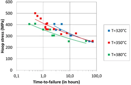
I-SCC susceptibility was studied on un-irradiated CWSR Zy-4, on smooth specimen, in the temperature range from 320°C to 380°C [3] (see the results on Figure 1). I-SCC was also studied on
P a g e
3 | 16
smooth specimen of un-irradiated CWSR Zy-4, called Zy-4 X11 in this paper, in the temperature range from 350°C to 488°C [5] (see the results on Figure 2). The irradiated CWSR Zy-4 was studied at the temperature of 350°C [6] on smooth specimen (see Figure 3).
Figure 1: Inner pressure tests at constant pressure on smooth specimen under iodine vapor environment. Effect of the temperature on I-SCC susceptibility of un-irradiated CWSR Zy-4 cladding [3]
Figure 2: Inner pressure tests at constant pressure on smooth specimen. Effect of the temperature on I-SCC susceptibility of un-irradiated CWSR Zy-4 (X11 batch) cladding [5]. Comparison of the results
P a g e
4 | 16
Figure 3: Inner pressure tests at constant pressure on smooth specimen. I-SCC susceptibility of irradiated CWSR Zy-4 cladding [6]. Comparison of the results obtained under iodine vapor
environment with results obtained under inert environment.
I-SCC susceptibility (as defined as the difference between the time-to-failure obtained under the iodine vapor environment and the time-to-failure obtained under the inert environment) is decreasing with temperature. At the opposite, the more the temperature increases the more the I-SCC times-to-failure decrease (together with the times-to-failure obtained under the inert environment). The kinetic of the I-SCC fracture is accelerated by the temperature. The irradiation increases the I-SCC susceptibility of the CWSR Zy-4. On un-irradiated material, there is an apparent stress threshold of about 240 MPa that seems to be independent of the temperature between 320°C and 380°C. But the conclusion is not apparent for temperatures above (420°C and 488°C).
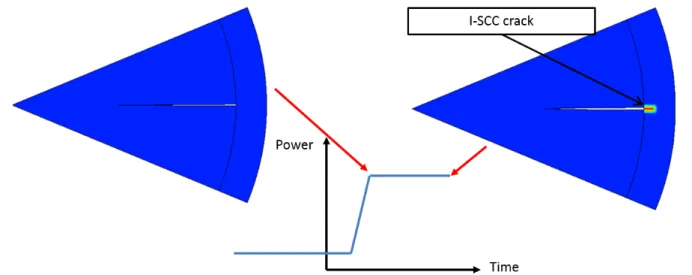
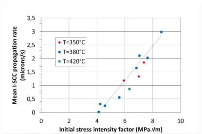
In order to evaluate the I-SCC crack growth rate and the I-SCC tenacity “KSCC”, internal pressurization
tests have also been carried out on pre-cracked specimens. Some results were obtained at different temperatures from 350°C to 420°C on un-irradiated CWSR Zy-4 [7] (see the results on Figure 4). The pre-cracking procedure is a fatigue-corrosion procedure and is described in [7]. Some results were obtained for irradiated CWSR Zy-4 at 350°C [8] with a fatigue procedure described in [9].
The results give mean propagation rates “V” as a function of the initial stress intensity factor “K0”
applied to each specimen. The mean propagation rate “V” is expressed as a function of the time-to-failure “tF”, and the difference between the final I-SCC crack depth “af” and the pre-crack depth “a0”
both measured post-mortem.
𝑉𝑉 =𝑎𝑎𝑓𝑓𝑡𝑡− 𝑎𝑎0
𝐹𝐹 (Eq 2)
“K0” is expressed in (Eq 3) as a function of the mean hoop stress “σθθ” ,as defined in (Eq 1), and the
pre-crack depth “a0”.
P a g e
5 | 16
Figure 4: Inner pressure tests at constant pressure on pre-cracked specimen. Effect of temperature on I-SCC tenacity (KSCC=4 MPa.√m) and on the I-SCC propagation rate.
Figure 5: Inner pressure tests at constant pressure on pre-cracked specimen. Effect of the irradiation on I-SCC tenacity (KSCC=1 MPa.√m on irradiated CWSR Zy-4).
I-SCC tenacity and the propagation rate seem to be independent of the temperature. The irradiation decreases the I-SCC tenacity of the CWSR Zy-4.
I-SCC propagation times appear to be short in comparison to the usual initiation times (few minutes versus hours respectively). As a consequence, the experimental time-to-failure can be assimilated to the time to initiate an I-SCC crack on the smooth specimen.
3 Results and modeling
3.1 Simulation of the inner pressure experiments
To simulate the inner pressure tests, finite-element simulations were performed with CAST3M [1] in the 2D radial-tangential plane of the cladding. The viscoplastic behavior of the cladding was simulated with an orthotropic viscoplastic model [10] for irradiated or un-irradiated Zy-4 cladding. This model is implemented in CAST3M through the MISTRAL module [11].
P a g e
6 | 16
Figure 6 : On the left, 2D finite element mesh used in the simulations with the symmetrical boundary conditions (red lines) and the pressure applied at the inner wall of the cladding (green line). On the
right, an example of the mesh used for the calculations with the Kachanov-Miller’s model. The internal pressure is applied by radial nodal forces at the inner wall of the cladding. The internal pressure also creates an axial resultant force F on the end caps of the specimen. The value of F is a function of the internal pressure P and the inner radius Ri n of the cladding:
𝐹𝐹 = 𝑃𝑃. 𝜋𝜋. 𝑅𝑅𝑖𝑖𝑖𝑖2 (Eq 4)
In order to take into account F, the simulations were performed using the assumption of the generalized plane strain. In this assumption, the resultant axial load F is applied to the mesh at the center of the generalized plane strain center which is situated at the center of the cladding. In the example shown in the left of the Figure 6, the simulated angle is θ=22.5°, so the force applied in the calculations (Fapplied) is equal to F/16.
𝐹𝐹𝑎𝑎𝑎𝑎𝑎𝑎𝑎𝑎𝑖𝑖𝑎𝑎𝑎𝑎 =𝐹𝐹. 𝜃𝜃2. 𝜋𝜋𝑟𝑟𝑎𝑎𝑎𝑎 (Eq 5)
The geometry of the mesh was recomputed after each step of calculation. In particular, the radial nodal forces applied at the inner wall of the cladding and the axial load were recomputed after each step. As a consequence, the hoop stress defined in (Eq 1) represents its initial value.
3.2 I-SCC modeling with the Kachanov’s model
To describe I-SCC, the Kachanov’s damage model [12] as written in (Eq 6) has been chosen. 𝑑𝑑𝑑𝑑
𝑑𝑑𝑡𝑡 = 𝐴𝐴〈 𝜎𝜎𝜃𝜃𝜃𝜃
1 − 𝑑𝑑 − 𝜎𝜎0〉𝑖𝑖 𝑤𝑤𝑤𝑤𝑡𝑡ℎ < 𝑋𝑋 >= �𝑋𝑋 𝑤𝑤𝑖𝑖 𝑋𝑋 > 00 𝑤𝑤𝑖𝑖 𝑋𝑋 < 0 (Eq 6)
This model describes the evolution of a damage variable D as a function of an effective hoop stress (σθθ/(1-D)) and a threshold stress σ0. The scalar “A” and the exponent “n” are parameters of the
model. The damage variable D is a scalar that ranges from 0 to close to 1. Before any damage occurred, D equals 0. Then, as long as the effective hoop stress is higher than the threshold stress σ0,
D increases with time.
3.3 Kachanov’s model used in post-treatment of FE simulations
The Kachanov’s model can be used in post-treatment of the FE simulations. The effective σθθ used in
(Eq 6) is the hoop stress calculated at the inner wall of the cladding, the value D=1 stands for the initiation of an I-SCC crack at the inner wall of the cladding, in the calculations. Because the I-SCC
P a g e
7 | 16
propagation time is short in comparison to the initiation time, the time calculated to initiate a crack with Kachanov’s model (D=1) can be compared to the experimental times-to-failure.
A set of parameters was identified for the un-irradiated CWSR Zy-4 in [3], on the results presented on Figure 1. The effect of the temperature on I-SCC is taken into account with an activation energy Q as written in (Eq 7). The stress threshold σiodine=240 MPa appeared to be independent of the
temperature.
𝑑𝑑𝑑𝑑
𝑑𝑑𝑡𝑡 = 𝐴𝐴𝐼𝐼𝑜𝑜𝑎𝑎𝑖𝑖𝑖𝑖𝑎𝑎. 𝑒𝑒−𝑄𝑄𝑇𝑇〈 𝜎𝜎𝜃𝜃𝜃𝜃
1 − 𝑑𝑑 − 𝜎𝜎𝐼𝐼𝑜𝑜𝑎𝑎𝑖𝑖𝑖𝑖𝑎𝑎〉𝑖𝑖𝐼𝐼𝐼𝐼𝐼𝐼𝐼𝐼𝐼𝐼𝐼𝐼 (Eq 7)
The times-to-failure calculated with the Kachanov’s model are compared to the experimental results on Figure 7. As an illustration, the times at which the calculated Diametrical Strain “DS” is larger than 40% are plotted on the figure under the name “Inert-DS>40%” curves. These curves illustrate the times-to-failure that could be obtained in an inert environment. In that figure (and the following figures), it is assumed that the times-to-failure calculated with the Kachanov’s model cannot be longer that the times-to-failure evaluated with the “Inert-DS>40%” curves.
Figure 7: Inner pressure tests at constant pressure on smooth specimens. Comparison of the Kachanov’s model with the experimental results obtained on the un-irradiated CWSR Zy-4 [3].
P a g e
8 | 16
The Kachanov’s model, used with the set of parameters identified above, has been applied to the un-irradiated CWSR Zy-4 (X11 batch) on the Figure 8. The I-SCC susceptibility of the material is slightly over-estimated at 350°C. At 420°C and 488°C, the “Inert-DS>40%” curves are close to the experimental times-to-failure obtained under an inert environment. At 420°C, the Kachanov’s model and the “Inert-DS>40%” are very close while they are superposed at 488°C. It is consistent with the small I-SCC susceptibility of the un-irradiated CWSR Zy-4 (X11 batch) at these temperatures. It can be concluded that the Kachanov’s model, identified for a range of temperature from 320°C to 380°C in [3], with an apparent stress threshold of 240 MPa, extrapolates well to the results obtained at 420°C and 488°C too.
Figure 8 : Inner pressure tests at constant pressure on smooth specimens. Comparison of the Kachanov’s model with the experimental results obtained on un-irradiated CWSR Zy-4 (Zy-4 X11
batch) [5].
The parameters of (Eq 7) were identified for the irradiated CWSR Zy-4. Only the activation energy “Q” was fixed to its value identified on un-irradiated CWSR Zy-4 [3]. The Kachanov’s model for irradiated CWSR Zy-4 is compared to the experimental results on Figure 9. As an illustration, the times at which the calculated Diametrical Strain “DS” is larger than 20% are plotted on the figure.
P a g e
9 | 16
Figure 9 : Inner pressure tests at constant pressure on smooth specimens. Comparison of the Kachanov’s model with the experimental results obtained on irradiated CWSR Zy-4 [6]. The effects of
the temperature are extrapolated with the Kachanov’s model.
3.4 Coupled Kachanov’s model in CAST3M
In order to simulate both the initiation and the propagation of a crack, the Kachanov’s model can be coupled to the viscoplastic models of the cladding. For that purpose, it has been implemented in the MISTRAL module and coupled to the viscoplastic models available in that module [13].
To simulate the crack opening, a crack strain tensor “εf”, as described in the Ottosen’s model [14],
has been added to the other type of strains in the MISTRAL module. It’s a method to make the coupled damage model independent of the size of the mesh used in the calculation [14]. For an application to tangential direction of the cladding, the tangential component is the only non null value of the tensor. The tangential component is written in (Eq 8) as a function of the length Lθ of the
elements in the tangential direction and of the critical opening of the crack “uC”.
𝑑𝑑𝜀𝜀𝜃𝜃𝑓𝑓 𝑑𝑑𝑡𝑡 = 𝑑𝑑𝑑𝑑 𝑑𝑑𝑡𝑡 . 𝑢𝑢𝐶𝐶 𝐿𝐿𝜃𝜃 𝑤𝑤𝑤𝑤𝑡𝑡ℎ 𝐺𝐺0= 1 2 . 𝜎𝜎0. 𝑢𝑢𝐶𝐶 (Eq 8)
The critical crack opening “uC” and the stress threshold σ0, as defined in (Eq 6) in the Kachanov’s
model, allow to define the minimal fracture energy “G0” of the model.
The Figure 10 illustrates the response of the coupled Kachanov’s model under a uni-directional loading which consists in applying a constant strain rate “V”, on one element, with the properties of the cladding in its tangential direction (with the viscoplastic model for the CWSR Zy-4 [10]). The fracture energy “G”, which is defined as the area under the curve in this figure, tends to “G0” as the
applied strain rate “V” decreases. It can be noticed that the displacement-to-failure is equal to the critical crack opening “uC” plus a viscoplastic elongation of the material. For the lowest strain rates
“V”, the viscoplastic elongation is neglectible and the displacement-to-failure is equal to the critical crack opening “uC”.
P a g e
10 | 16
Figure 10: Uni-directional response of the Kachanov’s model coupled with a viscoplastic model in CAST3M, at different uni-directional constant strain rate V. The calculation was made on one element, with σ0=100 MPa and uC=0.5 microns. The curves obtained with V=10-7 s-1 and V=10-6 s-1 are
superposed and define the minimal fracture energy “G0”.
In order to take into account the embrittlement of the cladding due to the local iodine content “I” in the material, the Kachanov’s model (Eq 7) is re-written as a function of embrittlement functions A(I) and σ0(I) in (Eq 9):
𝑑𝑑𝑑𝑑
𝑑𝑑𝑡𝑡 = 𝐴𝐴(𝐼𝐼). 𝑒𝑒−𝑄𝑄𝑇𝑇〈 𝜎𝜎𝜃𝜃𝜃𝜃
1 − 𝑑𝑑 − 𝜎𝜎0(𝐼𝐼)〉𝑖𝑖 (Eq 9)
The critical crack opening “uC” writes as a function of the embrittlement function G0(I) deduced from
(Eq 10):
𝐺𝐺0(𝐼𝐼) =12 . 𝜎𝜎0(𝐼𝐼). 𝑢𝑢𝐶𝐶(𝐼𝐼) (Eq 10)
The Figure 11 presents the embrittlement functions according to the local iodine content “I”. When “I” is lower than a threshold of iodine content “IC1”, there is no embrittlement of the material. The Kachanov’s model is supposed to model the damage of the material under an inert environment. When “I” is higher than a saturation iodine content “IC2”, the I-SCC susceptibility of the material does not change. The local iodine content “I” and the parameters IC1 and IC2 are dimensionless quantities.
P a g e
11 | 16
The local iodine content “I” is assumed to follow I-SCC Miller’s model [15]. This model is based on the Fick’s law of diffusion. Assuming that iodine does not diffuse in the zirconium, except in the I-SCC crack or at the tip of a crack, the Fick’s law was written as in (Eq 11) in [15].
𝑑𝑑𝐼𝐼 𝑑𝑑𝑡𝑡 =
1
𝜏𝜏(𝐼𝐼𝐸𝐸𝐸𝐸𝑇𝑇− 𝐼𝐼) (Eq 11)
This equation is suitable for a 2D Radial-Tangential FE application. In (Eq 11), IEXT is the “external
iodine load”. It this paper, it is a dimensionless quantity. Both, the iodine load “IEXT” and the local
iodine content “I” are fields of values defined on all the elements of the mesh in the FE simulations. The parameter τ in (Eq 11) is a period of time that is characteristic of the diffusion of iodine, limited to the crack and the tip of a crack, in the zirconium. This parameter could depend on the local mechanical fields as in Miller’s model [15] but was not taken into account in this paper.
The coupled Kachanov’s model used with the Miller’s model described above is called Kachanov-Miller’s model in the following.
Before any I-SCC crack is initiated in the calculation, the value of IEXT is set to 0 everywhere except in
one element of the inner wall of the cladding chosen arbitrarily. In that element, the local iodine content “I” evolves from 0 to the local non null value of IEXT. The evolution of the local iodine content
“I” can lead to the local embrittlement of the cladding and to a subsequent local damage. The “external iodine load” IEXT is updated after each step of calculation in CAST3M according to the
updated position of the I-SCC crack, so that, the values of IEXT are 0 everywhere in the mesh except in
an I-SCC crack and at the tip of an I-SCC crack, as illustrated in Figure 12.
Figure 12: Simulation of the I-SCC crack with the Kachanov-Miller’s model. The iso-values of the external iodine load « IEXT » that range from 0 (blue) to 1 (red) are depicted. The external iodine load
starts at the inner wall of the cladding and follows the I-SCC crack that runs along the radius of the cladding, at different time steps (from the left to the right).
The “external iodine load” can be updated according to the position of the damaged zone. The damaged zone is defined as the zone where D>Dmin. It includes the I-SCC crack. In the following, the “external iodine load” was updated according to the “damaged zone” with Dmin=0.01.
The Kachanov-Miller’s model, has been applied to the simulation of the inner pressure tests on irradiated CWSR Zy-4. Both the tests realized on smooth (see Figure 3) and pre-cracked specimens (see Figure 5) have been simulated.
The Figure 13 presents the results obtained with the Kachanov-Miller’s model applied to simulations of inner pressure tests at constant pressure on irradiated CWSR Zy-4 smooth specimens. The parameters under iodine of the embrittlement functions (see Figure 11) were those identified with the Kachanov’s model used in post-treatment, as described in (Eq 7) and Figure 9. The parameters under inert environment of the embrittlement functions were arbitrarily chosen to avoid any damage without iodine. The parameters IC1 and IC2 are arbitrarily set to 0.2 and 0.5 respectively in order to saturate the iodine embrittlement. I-SCC initiation and failure of the smooth specimens are properly
P a g e
12 | 16
simulated by the Kachanov-Miller’s model. I-SCC cracks evolve fast enough in the calculations to conclude that the times-to-failure and the times-to-initiate an I-SCC cracks are close in the calculations as in the experimental tests.
Figure 13: Inner pressure tests at constant pressure on smooth specimen. Comparison of the Kachanov-Miller’s model with the experimental results obtained on irradiated CWSR Zy-4 [6]. Each
curve represents the time required to initiate a crack or to develop a crack of depth A in the calculations.
The Figure 14 and the Figure 15 present the results obtained with the Kachanov-Miller’s model applied to simulations of inner pressure tests at constant pressure on pre-cracked specimens, with 2 different pre-cracks “A” in the calculations and 2 different sizes of the mesh “L”, respectively. The pre-crack is simulated in affecting D=1 to a row of elements as initial values in the calculations. The calculations are post-treated like the experiments thanks to the (Eq 1), (Eq 2) and (Eq 3). As expected, the result of the model is the same for a given initial stress intensity factor, whatever the depth of the pre-crack “A” in the calculation. The result is independent of the size of the elements of the mesh “L” thanks to the use of the crack strain tensor “εf” as defined in (Eq 8) from [14].
Figure 14 : Inner pressure tests at constant pressure on pre-cracked specimens. Comparison of the Kachanov-Miller’s model with the experimental results obtained on irradiated CWSR Zy-4 [8], for 2 values of the depth of the pre-crack “A” in the calculations. On the left, the pre-crack is represented by the elements where D=1 (red) with D=0 (blue) anywhere else. Only a portion of the mesh used in
P a g e
13 | 16
Figure 15 : Inner pressure tests at constant pressure on pre-cracked specimen. Comparison of the Kachanov-Miller’s model with the experimental results obtained on irradiated CWSR Zy-4 [8], for 2
values of the size of the mesh “L” in the calculations.
The calculated I-SCC tenacity “KSCC” is close to the experimental value (KSCC=1 MPa.√m). In the
calculation, the I-SCC propagates when the local tangential σθ stress is larger than the I-SCC stress
threshold σiodine. The I-SCC tenacity “KSCC” and the I-SCC stress threshold tend to have the same
mechanical meaning. They are both independent of the temperature in the range 320°C to 380°C ([3] and [7]).
The I-SCC propagation rate is under-evaluated with the set of parameters that predicts correctly the I-SCC initiation. The set of parameters had to be modified to properly evaluate the I-SCC propagation rate (see Figure 16). The Aiodine parameter, as defined in Figure 11, was multiplied by 10.
Figure 16: Inner pressure tests at constant pressure on pre-cracked specimen. Comparison of the Kachanov-Miller’s model with the experimental results obtained on irradiated CWSR Zy-4 [8]. Effect of
P a g e
14 | 16
4 Future works
The Kachanov-Miller’s model was implemented in Alcyone in 2D-Rθ and is to be implemented in Alcyone 3D [16]. The goal of this implementation is to enable a good discrimination of failed and non-failed ramps. In Figure 17, an I-SCC crack initiated and developed from the inner wall to the outer wall of the cladding, assuming that the “external iodine load” conducted to saturated iodine embrittlement in the calculation.
Figure 17: Example of a ramp test simulated with Alcyone and the Kachanov-Miller’s model in the cladding. The I-SCC crack initiates and propagates in front of a crack in the pellet during the upper
level of the ramp test.
5 Conclusions
The inner pressure tests carried out at constant pressure, under iodine vapor environment, on smooth CWSR Zy-4 specimen, tend to reveal a hoop stress threshold for I-SCC. This stress threshold seems to be independent of the temperature in the range 320°C to 380°C.
This result is consistent with the fact that the I-SCC tenacity “KSCC” seems to be independent of the
temperature too.
The level of stress threshold is about 240 MPa on un-irradiated CWSR Zy-4. This value is close to the stress threshold of 300 MPa exhibited in [17] on un-irradiated CWSR Zy-4 too. The stress threshold is about 150 MPa on irradiated CWSR Zy-4.
The Kachanov’s model, used in post-treatment of finite-element calculations, was used to model the I-SCC initiation. A set of parameters was identified, from inner pressure tests under iodine vapor, for both un-irradiated and irradiated CWSR Zy-4.
This set of parameters was used in the Kachanov-Miller’s model presented in this paper. The model properly simulated both I-SCC initiation and I-SCC tenacity “KSCC” for irradiated CWSR Zy-4. It tends to
give the same physical meaning to the I-SCC stress threshold and to the I-SCC tenacity “KSCC” in the
calculations. The I-SCC propagation rates were under-estimated with that set of parameters. In order to better evaluate the I-SCC propagation rates, some parameters had to be re-evaluated.
6 References
P a g e
15 | 16
[2] O. Fandeur, “Etude expérimentale et modélisation de la corrosion sous contrainte du Zircaloy-4”, PhD thesis, Ecole Centrale de Paris, 2001.
[3] T. Jézéquel, "Stress corrosion crack initiation of Zircaloy-4 cladding tubes in an iodine vapor environment during creep, relaxation, and constant strain rate tests", PhD thesis, ENSIACET, 2016, To be published
[4] C. Anghel, A.-M. Alvarez Holston, G. Lysell, S. Karlsson, R. Jakobsson, J. Flygare, S.-T. Mahmood, D. Le Boulch, I. Arimescu, “Experimental and Finite Element Modeling Parametric Study for Iodine-Induced Stress Corrosion Cracking of Irradiated Cladding”, Proceedings of Top Fuel 2010, Orlando, Florida, USA, September 26-29, 2010, paper 111 [5] L. Rouillon, F. Lefebvre, "Influence de la température d’essai sur le développement des
fissures de CSC dans le Zy-4 testé en pressurisation interne", Note technique CEA-Grenoble DTP/SECC 97/062A.
[6] L. Fournier, L. Rouillon, "Comportement en CSC par l’iode du Zy-4 irradié 1 cycle REP", Note technique CEA-Saclay, DMN/SEMI/LCMI/ NT/00-045/A.
[7] J. Fouchet, G. Delette, L. Rouillon, "Caractérisation de la phase transgranulaire lors de la fissuration par CSC du Zy-4 détendu en milieu iodé", Note technique CEA-Grenoble DTP/SECC 98/062A.
[8] I. Schuster, C. Lemaignan, J. Joseph, "Testing and modelling the influence of irradiation on iodine-induced stress corrosion cracking of Zircaloy-4", Nucl. Eng. Design. 156 (1995) p. 343. [9] C. Lemaignan, “Controlled Cracking of Tubes”, International Journal of Pressure Vessels &
Piping, 15, pp. 241-249 (1984).
[10] A. Soniak, N. L’Hullier, J.P. Mardon, V. Rebeyrolle, P. Bouffioux, C. Bernaudat, "Irradiation creep behavior of Zr-base alloys", in: Proceedings of 13th ASTM. International Symposium on Zirconium in the Nuclear Industry, Annecy, 2001, STP 1423, pp. 837-862.
[11] R. Limon, S. Lehmann, "A creep rupture criterion for Zircaloy-4 fuel cladding under internal pressure", Journal of Nuclear Materials, 335 (2004), pp. 322–334.
[12] L. M. Kachanov, “Rupture Time Under Creep Conditions”. Int. J. Fract., vol. 97, no. 1–4, pp. 11–18, Apr. 1999.
[13] D. Le Boulch, C. strub, N. Hourdequin, ‘’Modélisation de la Corrosion Sous Contrainte par l’Iode. Présentation d’un modèle d’endommagement couplé au comportement des alliages de Zirconium dans MISTRAL’’, Note technique CEA-Saclay DMN/SEMI/LCMI NT/2008-013/A. [14] N.S. Ottosen, "Constitutive model for short time loading of concrete", Journal of
Engineering Mechanics, ASCE, vol. 105, 1979, pp. 127-141.
[15] A.-K. Miller, H. Ocken, A. Tasooji, "Iodine stress corrosion cracking of Zircaloy: laboratory data: a phenomenological model, and predictions of in-reactor behavior”, Journal of Nuclear Materials 99 (1981) 254-268.
[16] E. Fédérici et al, “Recent advances in the understanding of the physical mechanisms involved in PCI I-SCC and their modeling with ALCYONE application”, 2016, this workshop
P a g e
16 | 16
[17] P. Magnusson, D. Le Boulch, A. Puranen, D. Jädernäs, G. Lysell, "An experimental and Finite Element modeling study of cladding strain and localized stresses under simulated iodine-induced stress corrosion cracking", in: Proc. WRFPM 2014, Sendai, Japan, 2014
![Figure 7: Inner pressure tests at constant pressure on smooth specimens. Comparison of the Kachanov’s model with the experimental results obtained on the un-irradiated CWSR Zy-4 [3]](https://thumb-eu.123doks.com/thumbv2/123doknet/12909164.372247/8.892.239.662.449.715/pressure-constant-pressure-specimens-comparison-kachanov-experimental-irradiated.webp)


![Figure 13: Inner pressure tests at constant pressure on smooth specimen. Comparison of the Kachanov-Miller’s model with the experimental results obtained on irradiated CWSR Zy-4 [6]](https://thumb-eu.123doks.com/thumbv2/123doknet/12909164.372247/13.892.241.643.193.451/pressure-constant-pressure-specimen-comparison-kachanov-experimental-irradiated.webp)
![Figure 16: Inner pressure tests at constant pressure on pre-cracked specimen. Comparison of the Kachanov-Miller’s model with the experimental results obtained on irradiated CWSR Zy-4 [8]](https://thumb-eu.123doks.com/thumbv2/123doknet/12909164.372247/14.892.178.743.133.415/pressure-constant-pressure-specimen-comparison-kachanov-experimental-irradiated.webp)