HAL Id: hal-01592739
https://hal.archives-ouvertes.fr/hal-01592739
Submitted on 25 Sep 2017
HAL is a multi-disciplinary open access
archive for the deposit and dissemination of
sci-entific research documents, whether they are
pub-lished or not. The documents may come from
teaching and research institutions in France or
abroad, or from public or private research centers.
L’archive ouverte pluridisciplinaire HAL, est
destinée au dépôt et à la diffusion de documents
scientifiques de niveau recherche, publiés ou non,
émanant des établissements d’enseignement et de
recherche français ou étrangers, des laboratoires
publics ou privés.
Distributed Object-Oriented Design of Autonomous
Control Systems for Connected Vehicle Platoons
Sebti Mouelhi, Daniela Cancila, Amar Ramdane-Cherif
To cite this version:
Sebti Mouelhi, Daniela Cancila, Amar Ramdane-Cherif. Distributed Object-Oriented Design of
Au-tonomous Control Systems for Connected Vehicle Platoons. 2017 22nd International Conference
on Engineering of Complex Computer Systems (ICECCS), Nov 2017, Fukuoka, Japan. pp. 40-49,
�10.1109/ICECCS.2017.32�. �hal-01592739�
Distributed Object-Oriented Design of Autonomous
Control Systems for Connected Vehicle Platoons
Sebti Mouelhi
ECE Paris – ´Ecole d’ing´enieurs F75015, Paris, France Email: [email protected]
Daniela Cancila
CEA-LIST, CEA Saclay F91191, Gif-sur-Yvette, France
Email: [email protected]
Amar Ramdane-Cherif
Laboratoire d’Ing´enierie des Syst`emes de Versailles (LISV), UVSQ
F78140, V´elizy, France Email: [email protected]
Abstract—The contribution of this paper is articulated around a new software design approach of autonomous control systems for connected vehicle platoons. Our control system is distributed and real-time based on object-oriented component-based method of design that brakes with the industrial traditions subject to cyclic OS-free approaches. We illustrate our design by relevant case studies of the longitudinal speed control widely studied in industrial and academic research around automotive platooning. Our software is mainly implemented using the Ada standard of programming (in particular the annexes D and E of real-time and distributed systems). The distribution in our software is managed by the versatile middleware PolyORB. The control scenarios and communication aspects covered by the case studies are animated by wheeled robot prototypes commanded by single-board ARM Cortex computers under real-time Linux kernels.
Index Terms—Embedded systems, distributed architectures, object-oriented components, real-time, smart automotive systems, vehicle platooning.
I. INTRODUCTION
The impact of massive usage of cars in terms of traffic jams and air pollution makes the mastery of automotive systems of a paramount importance and a hot topic in today’s politics. Over the last decades, several solutions have been proposed and shaped. They range from increasing road capacities by creating more roads and adopting smart circulation modalities (platoon-ing, green wave, smart roads, etc) to the encouragement of car sharing and the choice of public and electric transport [1]. Most of these solutions have shown positive affects but have not been able to solve congestion problems. In fact, the traffic jams have become more severe because of the growing number of vehicles and hence, more drastic and innovative solutions are needed. Few years ago, embedded electronics and software advances are transforming progressively computers to become ambient in human mobility which renders transport systems more advanced. One of the innovations are Advanced Driver Assistance Systems (ADAS) that aim to improve efficiency, safety and comfort using advanced information and commu-nication technologies [2]. In this context, the industrial actors of automotive systems are becoming increasingly interested in embedding sensors and actuators massively in cars to make them sensitive to their external environment circumstances and intelligent by allowing them to take decisions on behalf of or to assist the driver for safer and less expensive journey and more fluid and nature-friendly traffic.
However, current mature industrial products are limited by the driver able to overrule the system. To make vehicles highly cooperative, a system that automates human tasks with high performance electronic and networking counterparts would be ultimate. For example, enabling data exchange and automation in vehicle platooning systems would allow more reliable and faster control of circulation and smaller inter-vehicle headway which increase road capacities and reduce energy consump-tion. Semi-autonomous platooning control systems have been a lively research topic for decades. A strong theoretical focus already exists on the longitudinal and lateral control [3] and string stability [4].
As a first contribution, we propose an automatic process to control the longitudinal speed and ensure collision avoidance in vehicle platoons. Two simple scenarios are presented and studied in order to illustrate the speed control system: i) the tail-merging of a new connected vehicle in a platoon already in circulation, and ii) the propagation of the braking alarm to followers by the leader’s detection of obstacles. As said earlier, many theoretical contributions were proposed to deal with the physical aspects of longitudinal and lateral control and string stability in vehicle platooning. Our approach to deal with the longitudinal speed control is purely algorithmic and takes advantage from Vehicle-To-Everything (V2X) communication technologies recently being used in automotive smart systems under several forms and network support and standards like the IEEE 802.11p [5]. We made the choice to not rely on rigorous physical approaches of analysis and simulation of the control behavior because they require a thorough knowledge of different parameters (like vehicles masses, friction errors, loss of energy, etc) difficult to consider in robot prototypes. A deep investigation of these issues quickly derails us from the scope of our work rather oriented towards the software engineering issues in Intelligent Transportation Systems (ITS).
On the other hand, automation is clearly critical in this kind of systems: an equipment failure or malfunction may result in catastrophic outcomes and harms on people, environment and properties. Safety is strictly required face to this emergence. We talk about High Integrity Safety-Critical (HISC) systems: the different parts of such systems are networked and coordi-nated with an intelligent software that understands and learns the state of its environment and takes sensible decisions under hard and/or soft real-time constraints.
In industry, the software layer of HISC systems is built using component-based cyclic reactive OS-free approaches [6]–[8]. Safety requirements are checked using the V-Model’s testing techniques, posterior formal proof, or prior incremental formal design. The classic test is out of step compared to the size and complexity of large-scale applications. Formal methods are usually used to check low level software requirements on the software components “separately” while nearly ignoring high level system requirements (covering in part the interoperability of components and their composite behavior) relevant to reach the required high level of integrity.
The second main contribution of this work is to demonstrate that the Distributed Object-Oriented Component-Based Design (DOOCBD) is appropriate to build HISC embedded software, scalable in concrete implementation, and can help solve the problems above. Object-oriented design has often been a hard sell to manufacturers of HISC systems in many areas like au-tomotive, railway, avionic, etc. Standards like [9], [10] require extensive verification processes and sometimes hard real-time difficult to carry on by the dynamic aspect and flexibility of object-oriented paradigms (polymorphism, dynamic dispatch, late binding, overriding, etc). Distribution is also penalizing because of its semantics (message passing, remote dispatch and procedure call, etc). The Ada ISO standard can decidedly settle these disadvantages. It has built-in strong typed pro-gramming language with powerful support for explicit tasking and concurrency, protected objects, design-by-contracts [11], compiler directives (pragmas), and other features allowing the developers to exploit the object-oriented assets while avoiding vulnerabilities and ensuring real-time. Ada is also provided with powerful compilers allowing the detection of run-time errors which improves safety and maintainability [12].
We present a software architecture of generic speed control in vehicle platoons using a DOOCBD approach. An object-oriented component is a unit of a third-party composition with environment-dependent interfaces provided and required [13] and may exhibit progressive behavior. By allowing distribution and object-orientation, component instances can communicate while being deployed in distant sub-systems. Unlike the cyclic reactive approaches, their interaction and data exchange are easy to trace and debug in the components implementation. Besides, they can be checked early during the design phase by using formal techniques for example. Our approach is flexible and suitable for the design of HISC communicating systems in general and ensure both safety and reliability for sub-systems individually but also for their interactive behavior.
Our design is implemented using the annexes D [14] and E [15] of the Ada Reference Manual resp. of real-time and distributed systems. The Annex E (abbreviated DSA) provides support for efficient distribution by making the middleware layer completely transparent and the development more easier. We opt for the middleware PolyORB [16], [17] maintained by AdaCore to deploy and animate the implementation. It supports many distribution models including CORBA [18] and DSA but also the Ravenscar profile [19] (a restricted tasking Ada subset used for hard real-time).
The platooning scenarios provided were tested on mock-up wheeled robots controlled by Arduino-based boards enslaved by ARM Cortex-A single-board computers on which our soft-ware distributed application is deployed and executed under real-time (Preempt RT) Linux kernels.
In Section II, we provide a brief survey about the common implementations of vehicle platooning systems and some of their underlying control problems. In Section III, we present the platooning case study scenarios considered in this paper. They are recalled gradually in the next sections to illustrate our contributions. In Section IV, we introduce our concept of object-oriented components and interoperability and explain with details our distributed software design of speed control in vehicle platoons. The Ada implementation, robot prototyping, distributed deployment, real-time considerations, and finally testing results are given in Section V. Conclusion discussions, related works and some of the future directions of our work are provided in Section VI.
II. VEHICLEPLATOONING,A BRIEF SURVEY
The concept of vehicle platooning aims to increase roads capacities and traffic fluidity. Vehicles are organized in tightly controlled platoons that operate close together. A highway for example can accommodate more vehicles when organized as platoons compared to classic human driving conditions [1].
Adaptive Cruise Control (ACC) systems are well-known in vehicle platooning systems and currently available in many of upscale vehicles. A vehicle with ACC is commonly equipped with front radars. When a preceding vehicle is detected by these radars, the ACC system adjusts the vehicle’s velocity in order to maintain a fixed time-gap to the preceding vehicle. This all happens without the driver’s intervention. The follow-up is the Cooperative Adaptive Cruise Control (CACC). This concept augments ACC with wireless communication capabil-ities and enables a closer inter-vehicular cooperation which improves the traffic flow even more. Wireless communication allows vehicles to extend view beyond the line of sight of the front radars and allows faster transmission of speed updates between vehicles. However, in both kinds of system, the driver is partly responsible for the vehicle’s operation [20].
By adopting an Autonomous Connected Vehicle Platooning (ACVP) concept, control becomes fully automated, driver-free and cooperative. The Automated Highway Systems (AHS) is a variant of ACVP systems and has been under research by the Program of Advanced Technology for Highway (PATH) for years [21], [22]. It aims to make vehicles in highways guided autonomously to their destination under both controlled and optimized traffic flow for maximum efficiency and safety. Platooning control functions
The main functions to control the behavior of vehicles in a platoon are mostly: longitudinal and lateral control, string stability, lane tracking and changing, maneuver coordination for platoon formation and split. We provide in the paragraphs below a brief description of these control functions and some of their related research contributions.
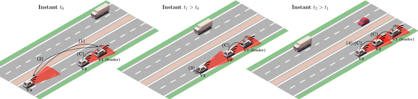
Instant t0 V3 V2 V1 (leader) (1) (2) (C) Instant t1> t0 V3 V2 V1 (leader) (3) (C) Instant t2> t1 V3 V2 V1 (leader) (4):(C) (C)
Fig. 1. Tail-merging in platoon already in circulation; step (1): V3 requests the references of vehicles covered by BS installed on the platoon’s leader vehicle (V1); step (2): BS sends back to V3 the references of V1 and V2; step (3): V3 tail-merges in the platoon (already composed of V1 and V2) and accelerates to catch up with V2; step (4): V3 controls (C) its velocity based on that of V2 in order to keep a minimal safety distance and avoid collision between them.
The longitudinal speed control [3], [23] consists in adapting the vehicle’s velocity compared to that of the preceding one using the powertrain and brakes. Implementations of longitudi-nal control are also highly dependent on the headway from the preceding vehicle. Front-radar and image-processing sensors are typically used to get the measurements of these inputs. It should provide comfortable ride for passengers and be accurate so that safety can be guaranteed.
The lateral control [3], [24] consists in keeping the vehicle in the middle of the road (or the lane) by tracking its median trajectory. Designing such functionality involves a trade-off between the ride quality and the system accuracy, just like for longitudinal control. The challenges handled in the design of lateral control systems include high-speed operation using a purely “look-down” sensor system without transitional lateral position measurements. It is also concerned with lane changing from the current lane to an adjacent one. This aspect of lateral control is considered to be the most challenging as it involves more vehicle dynamics, changes of the radar targets but also more coordination and communication between vehicles.
The string stability [4] ensures that range errors decrease by propagation along the vehicle stream. It is widely known that when the transfer function from the range error of a vehicle in the platoon to that of its follower has a magnitude value less than 1, string stability is guaranteed. V2X communication was shown to be necessary in order to achieve string stability with constant inter-vehicle spacing.
Platoon formation, also called joining or merging, is the term used for a situation where two platoons (or a platoon and one or several vehicles) are combined into one platoon. Platoon split is however the situation where one or several ve-hicles leave the platoon. Communication is obviously required in such scenarios to ensure safety and stability.
III. PLATOONCASESTUDIES
Sensing technologies like on-board sensors, cameras, radar, and lidar devices are mature nowadays and adopted by many car manufacturers. They are well-suited for ITS in general and ADAS in particular by allowing the drivers to be warned from impending dangers so that they take corrective actions, or the system to intervene on their behalf autonomously.
While these technologies are highly beneficial, our proposal relies on V2X communication technologies based on forceful wireless exchange of information between connected vehicles and infrastructure devices. They represent a major upgrade in improving passengers comfort, preventing dangers, but also they promote a smooth transition to fully automated autos. We consider two common control scenarios in ACVP systems based on V2X communications to illustrate our approach of software design detailed in depth in the next sections: 1) the tail-merging of a new connected vehicle in a platoon already in circulation, and 2) the propagation of braking alarms to followers when the leader vehicle detects an obstacle.
We consider three connected vehicles V1, V2 and V3. V1 and V2 are already forming a platoon of which V1 is the leader. At the instantt0 of Fig. 1 (left), in order to tail-merge in the platoon, V3 sends its remote reference by wireless to a mobile base station (BS) installed on the leader when entering its coverage area (step 1). In turn, BS sends back the references of V1 and V2 to V3 (step 2). We talk here about Vehicle-To-Base (V2B) communication. Once connection is established and the references of V1 and V2 are acquired, V3 can consequently communicate directly with each of them. We point here that the coverage area of BS should be larger than that of vehicles to detect the approach of new merging vehicles as soon as possible. At t1 > t0 of Fig. 1 (middle), V3 accelerates briskly to catch up with V2 (step 3). The front-radars of V3 and V2 are clearly used to compute the distances to their predecessors resp. V2 and V1. By approaching V2 at t2> t1 of Fig. 1 (right), V3 controls velocity so that collision with V2 is avoided by respecting a prefixed minimal inter safe distance. Besides, stability should be guaranteed for the platoon by preventing shake-up in case where a vehicle does not respect the safety distance to its predecessor and brakes prematurely (step 4). The speed control of a vehicle is defined based on the velocity of its predecessor communicated by Vehicle-To-Vehicle (V2V) under real-time determinism.
We propose an intuitive longitudinal speed control process, pragmatic and easy to implement. As said before, we abandon mathematical control approaches since they require a deep consideration of the system parameters in software design, rather considered to be the central focus of our work.
Safety zone Control zone Acceleration zone Successor Predecessor Vp Vs pr ps pc Xs Vs→ Vp Vs% Vs= 0
Fig. 2. Longitudinal speed control.
The relative distance between a vehicle and its predecessor is subdivided into three zones as schematized in Fig. 2:
• Safetyzone (SZ): this is the area behind the predecessor vehicle between its rear position pr and the limit the successor shall not cross, that is ps= pr− ds with ds is a constant safety distance;
• Control zone (CZ): this is the area beyond SZ between ps and the position from which the successor starts to stabilize gradually its regimeVsso that the safety distance ds is maintained between them, that is pc= ps− os with os is a relative distance called the stabilization offset; • Accelerationzone (AZ): being in this zone, the successor
is still far from the predecessor and has a leeway to accelerate briskly and reach CZ quickly.
When the successor’s front positionXsexceedspc, it requests, at periodic instants, the predecessor’s velocityVp (constant in Fig. 2) which in turn responds by sending the information before the next request. This is critical: the exchange delay should be deterministic to guarantee a safe and stable behavior. The successor adapts accordingly its acceleration so that both vehicles roll at the same velocity. The stabilization offset os shall be large enough to prevent bodywork shake-up during speed control. Shake-up occurs when the successor enters SZ while it is reducing velocity to align progressively with that of its predecessor, braking is triggered prematurely.
V3 V2 V1 (leader) Obstacle (1):(B) (2):(B)
Fig. 3. Platoon obstacle handling: the steps (1) and (2) represent the braking alarm (B) propagation to the followers by the leader’s detection of the obstacle.
The second control scenario is depicted in Fig. 3. When the leader detects an obstacle, it brakes immediately and alerts (by V2V) V2 to perform an emergency brake and propagate alert to V3. These situations are unpredictable and handled as aperiodic events in the control design (cf. Section IV).
IV. DESIGNAPPROACH
In this section, we present a DOOCBD design approach to handle V2X communications between vehicles in ACVP systems. Before presenting our software design approach, we start first by providing a preliminary description of distributed systems and object-oriented components.
A. Distributed systems and object-oriented components A distributed system is a set of distant computing nodes connected by a network. Each node incorporates one or several distributed partitions interacting locally within the node or remotely with partitions instantiated in other nodes. Each par-tition is a set of live software components. They may interact locally within the partition or remotely with components of other partitions in the same or distant nodes.
Component
Attributes f1, ..., fk (private) Required methods
r1, ..., rm
(callable from references to external local or remote component instances)
Output interfaces
Input interfaces Provided methods
a1, ..., an (public and private) Jobs
£j1, ...,£jl(behavioral periodic jobs) use
use
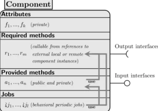
Fig. 4. Abstract representation of an object-oriented component.
A component is typically a description of an open entity interacting with others composing its environment. It accepts inputs provided by the environment, generates some outputs (or provides some services) and may express activities. In DOOCBD, a component is object-oriented consisting of a set of attributes and a set of named services and jobs. Concretely, a service is a method callable locally by the component (private or public) or by its environment (only public), and may require internal and external methods. A job (if defined) represents the actions and reactions impacting the component’s visible state, and may also require internal or external methods (cf. Fig. 4). Inputs to a component are the parameters passed as arguments to its provided methods and outputs are their return parameters or raised exceptions and errors.
We start by defining the concept of a component contextM which is a collection of object-oriented components. Given a componentM ∈ M, at run-time an instance c of M (c :: M) is an active running entity of the component M . It reserves resources (memory) for attributes, provides methods for open use, requires methods from components inM, and exhibits a progressive behavior by running jobs. A distributed system is seen as a collection of instance sets, each of them corresponds to a separate node or partition. A given node or partition may contain several instances of the same component and a given component may be instantiated in several nodes or partitions. From now on, we use the term “component” (for short) instead of object-oriented component.
Vehicle Attributes
- identifier : Integer - brake alarm : Boolean - velocity, acceleration : Float References
sct :: Speed Controller spd :: Speedometer bs :: @Base Station
platoon : (Integer, @Vehicle) map
Required methods + Get Acceleration Command + Get Velocity +@ Register Vehicle +@ Get Remote Vehicles
+@ Get Velocity +@ Trigger Brake Alarm Provided methods
+ Get Velocity (→ vel : Float) # Unknown Velocity + Trigger Brake Alarm
- Brake Jobs
£ Drive (period : Integer)
Base Station Attributes
- connected vehicles : (Integer, @Vehicle) map References
(No references)
Required methods (No required methods) Provided methods
+ Register Vehicle (id : Integer, veh : @Vehicle) # Illegal Vehicle Identifier + Get Remote Vehicles (→ ngbs : (Integer,@Vehicle) map)
# No Connected Vehicles Jobs
(No jobs)
Speed Controller Attributes
- speed request, acceleration command : Float References
sns :: Sensor spd :: Speedometer
Required methods
+ Get Distance To Obstacle
+ Get Velocity
Provided methods
+ Get Acceleration Command (→ acc : Float) # Erroneous Acceleration
- Compute Acceleration (dt : Float→ acc : Float) Jobs
£Dependent Control (period : Integer, pvel : Float) £Autonomous Control (period : Integer)
Speedometer Attributes
-velocity, distance : Float References
odo :: Odometer
Required methods + Get Traveled Distance Provided methods
+ Get Velocity (→ vel : Float) # Erroneous Velocity - Compute Velocity (dt : Integer→ vel : Float) Jobs
£ Update (period : Integer)
Sensor Attributes
- distance to obstacle : Float References
(No references)
Required methods (No required methods) Provided methods
+ Get Distance To Obstacle (→ dist : Float) # Erroneous Distance Jobs
£ Update (period : Integer)
Odometer Attributes
- absolute distance : Float References
(No references)
Required methods (No required methods) Provided methods
+ Get Traveled Distance (→ dist : Float) # Erroneous Distance Jobs
£ Update (period : Integer) V2B Sp eed Computer Distance Computer Sensing Engine Accelerator V2V
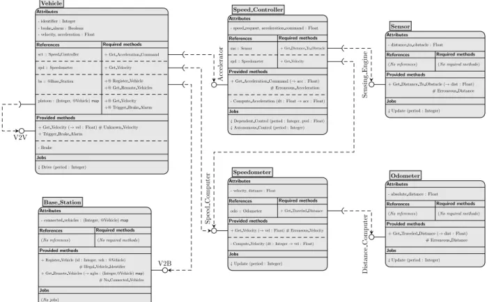
Fig. 5. Component static UML-like architecture.
Let’s X be the universe of variables and consider X ⊆ X, we define by T[x] the type of x ∈ X i.e., x:T[x]. We define a component M ∈ M by a tuple (FM,PM,JM,EM,RM) whereFM is the set of its attributesf :T[f],PM is the set of its provided methods, JM is the set of its jobs,EM is a set of references to instances of components in M, and RM is the set of its required methods. The set PM of provided methods is split intoPM+ andPM− resp. of public and private provided methods. We deduce obviously from the above definitions that RM ⊆ {b ∈ PN+, (∀N ∈ M(M), c ∈ EM andc :: N )} where M(M ) = {N ∈ M, PN+ 6= ∅} is the contextual environment of the componentM under M.
The input signature of a method a∈ PM ∪ RM is written bya(i1:T[i1], ..., ik:T[ik]→o1:T[o1], ..., ol:T[ol])#(e1, ..., em) where {i1, ..., ik} and {o1, ..., ol} are resp. the sets of input and return parameters of a, and {e1, ..., em} is the set of exceptionsthrowable bya. Methods with no return parameters are called void methods. The signature of a job b ∈ JM is written b(j1:T[j1], .., jp:T[jp]) where {j1, ..., jp} is the set of input parameters of b. Absence of input/return parameters or exceptions is represented by a void.
Jobs are periodic stateful tasks evolving in time i.e., they represent the component’s progressive operation within its environment while updating the attributes by sequential com-putations and method invocations. Methods are stateless one-shot programs invoked if needed by both local and remote environments. No evolving behavior is expected by method executions. Inter nodes and partitions method invocations are handled concurrently as aperiodic events with other tasks.
B. Software architecture
The static architecture shown in Fig. 5 presents the software components interfacing with various electronic control devices embedded in the connected vehicles of our ACVP system. The implementation of control scenarios of Section III is based on that architecture. We consider a component context composed of six components: Vehicle, Base Station, Speed Controller, Speedometer, Odometer and Sensor.
The component Speedometer calculates the attribute velocity of a vehicle by computing ∆d∆t where ∆t is time period and ∆d is the relative distance traveled during ∆t. The public (+) method Get Traveled Distance, provided by Odometer via the interface Distance Computer, returns the current traveled absolute distancesince the beginning of the journey. At each period∆t of the job (£) Update, ∆d is calculated by subtract-ing form the current absolute distance, the last measured one (attribute distance). Second, the current velocity (attribute) is the result of computing∆d∆t. Both of the operations are grouped in the private method Compute Velocity (-). It provides the public method Get Velocity (that returns the current value of velocity) to its contextual environment via the input interface Speed Computer which is both required by the components Speed Controllerand Vehicle according to Fig. 5.
The component Sensor is the software facet of front-radars. It computes the distance separating the vehicle to the nearest front obstacle (attribute distance to obstacle). It provides the method Get Distance To Obstacle to its contextual environ-ment through the interface Sensing Engine.
Speed Controlleris a central component responsible for the longitudinal speed control. It has two main jobs, the first one Autonomous Controlis the leader’s speed control task. Since the leader is the vehicle guiding the rest of the platoon, its velocity may be controlled automatically or by human driving. This job handles the obstacle detection, triggers braking, and initiates the propagation of braking alarms to followers (cf. Fig. 3). The second Dependent Control is the speed control task of the followers. The velocity of a follower vehicle is computed according to the principle explained in Section III and represented in Fig. 1 (middle and right) and Fig. 2. The pa-rameter pvel is the velocity value inputted from the predecessor when the vehicle’s front position crosses the borderpc of CZ. Both jobs compute an acceleration command (attribute) peri-odically based on a speed request (attribute) by calculating ∆v∆t where∆t is a time period and ∆v is the difference between the current speed request (defined by the control decision) and the current velocity recoverable by invoking the method Get Velocity of Speedometer. This operation is performed by the method Compute Acceleration. Speed Controller outputs periodically the acceleration command to adjust the engine velocity by providing the method Get Acceleration through the interface Accelerator.
The component Vehicle represents the software unit of a connected vehicle. It contains two main instance references sct and spd resp. of Speed Controller and Speedometer used to get the actual acceleration command and velocity in attributes. Besides, it contains also a reference bs to remote instance (@) of the component Base Station that represents the mobile BS installed on the leader. As soon as the V2B connection to BS is established, a new tail-merging vehicle to the platoon stores a remote reference to its Vehicle instance by it (integer) identifier in the map attribute connected vehicles by invoking Register Vehicle. It can acquire as return a map platoon con-taining references the other connected vehicles of the platoon by invoking Get Remote Vehicles. By the way, an instance of a connected vehicle provides the methods Get Velocity and Trigger Brake Alarm (via the interface V2V) to the others. It has a job Drive used to initialize the system and motors but also to adopt the autonomous driving mode if needed.
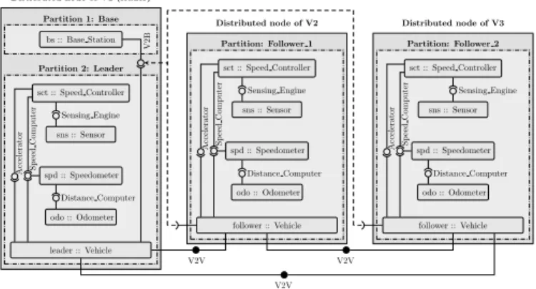
The dynamic distributed architecture is given in the model of Fig. 6. The component Vehicle is instantiated thrice in three partitions Leader, Follower 1 and Follower 2 running in three distributed nodes resp. dispatched in V1, V2 and V3. Locally within each node, each of them embodies component instances of Speed Controller, Speedometer, Odometer and Sensor. They also require remotely i) from each other, the methods of the interface V2V, and ii) those of the interface V2B from the component Base Station instantiated in a separate partition Base running in the leader’s node.
Att0(cf. Fig. 1), by having the intention to tail-merge in the platoon and being under the coverage area of BS, V1 acquires the reference of BS remote instance, registers itself into it by invoking Register Vehicle, and requests the references of other registered vehicles by invoking Get Remote Vehicles (step 1). BS responds by sending them back to V1 (step 2).
leader :: Vehicle
follower :: Vehicle follower :: Vehicle spd :: Speedometer odo :: Odometer sct :: Speed Controller sns :: Sensor bs :: Base Station spd :: Speedometer odo :: Odometer sct :: Speed Controller sns :: Sensor spd :: Speedometer odo :: Odometer sct :: Speed Controller sns :: Sensor Sp eed Computer Accelerator Distance Computer Sensing Engine V2B Sp eed Computer Accelerator Distance Computer Sensing Engine Sp eed Computer Accelerator Distance Computer Sensing Engine V2V V2V V2V
Distributed node of V1 (leader) Partition 1: Base Partition 2: Leader Distributed node of V2 Partition: Follower 1 Distributed node of V3 Partition: Follower 2
Fig. 6. Distributed dynamic architecture; interfaces are input and output.
Att1, V3 accelerates to catch up with V2 (step 3) as said before in Section III. No V2X communication is required because V3 is still rolling in AZ. At t2 (step 4), by entering CZ, V3 requests periodically the velocity of V2 (by calling remotely Get Velocity). We assume that synchronization is required between the caller body (the job Dependent Control of Speedometer instance) in V2 and that of the called method Get Velocity i.e.,the body of Dependent Control is blocked as long as Get Velocity does not return. This blocking time shall be bounded by the period of Dependent Control. A trick to implement this requirement is given at the end of Section V-D. The propagation of braking alarm is also handled using V2V exchange between vehicles as explained above in Section III and shown in Fig. 3. When the leader (V1) detects an obstacle in the road, it brakes immediately and notifies its direct follower (V2) by invoking the method Trigger Brake Alarm in which the private procedure Brake is executed to actuate the brakes. V2 performs the same actions to notify V3.
V. ROBOTPROTOTYPING ANDIMPLEMENTATION
We present in this section the software implementation and the robotic prototyping of our design method detailed in Section IV. Specifics about the distributed deployment of our application and respectfulness of real-time constraints are also provided. We start by presenting the robots architecture. A. Robots architecture
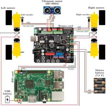
The architecture of Fig. 7 represents the hardware structure of our prototypes of four-wheeled robots. A robot is composed of: 1) four micro DC (Direct Current) geared motors used to rotate four wheels with a power supply of 7.5V, 2) two motor encoders with a resolution of 20 PPR (Pulses Per motor Revolution) which can be fixed on the front or rear motors, 3) an ultrasonic sensor (HC-SR04) positioned at the front of the robot, 4) a Romeo (DFRobot product) low-level slave robot controller used to efficiently interface (using Arduino functions) with the three first hardware components, and 5) a Raspberry Pi (RPi) master high-level control card on which our distributed software is deployed to command the Romeo board. The control outputs and the sensing inputs are wired between the two boards using the I2C bus.
.
.
.
.
.
.
.
.
.
.
.
.
.
.
...
...
.
.
.
....
.
.
.
.
.
+.
–.
+.
–.
.
.
.
.
.
.
.
.
.
Left motors Left encoder Right motors Right encoder Ultrasonic sensor (HC-SR04) Motors battery (7.5 V) Romeo card RPi card Echo T rig V CC GND VCC GND Interrupts (right) Interrupts (left) GND VIN GND M2 M1 GND I2C SCL 5V I2C SDA USB batteryFig. 7. Wheeled robot architecture; acronym legend of pins and connectors: GND (Ground), VCC/VIN/5V (Power-Supply), Echo (Ultrasonic Echo), Trig (Ultrasonic Chirp), SDA (Serial DAta line of I2C), SCL (Serial CLock line of I2C), M1 and M2 (Power inputs for resp. left and right motors).
B. Robot speed controller
The block diagram of Fig. 8 illustrates the speed control process of our wheeled robots. Light gray boxes are software instances of the design components (cf. Section IV-B). Dark gray boxes are some of the robot hardware components shown in Fig. 7. The velocity of a given robot in the platoon is controlled using two inputs: i) the errorerr (∆v) between the speed requestsr and the current velocity vc of the robot, and ii) the distance do to the nearest obstacle acquired by calling the method Get Distance To Obstacle from the instance sns of Sensor (cf. Section IV-B). The distance is computed using the duration uo from the moment the chirp output signal is emitted by the ultrasonic sensor until the echo input one is received. The current velocityvc is computed using the relative distance traveled during a period of the job Update of the instance spd of Speedometer based on the current absolute distance ad acquired by calling Get Traveled Distance from the instance odo of Odometer (cf. Section IV-B). The absolute distancead is computed based on the number of revolutions rl andrg resp. of the left and right motors which can be traced by getting the number of interrupts (pulses)il and ig registered resp. by the left and right encoders having a resolution of 20 PPR as mentioned above. The instance sct of Speed Controller computes periodically the acceleration commandctl using err anddo. If no braking alarm is triggered locally by the robot in case an obstacle is detected or remotely by other robots,ctl is supposed to be err∆t where∆t is the time period of one of the jobs Dependent Control (if follower) or Autonomous Control (if leader) as explained in Section IV-B.
sct :: Speed Controller
sns :: Sensor Ultrasonic sensor
Left motor Right motor Left encoder Right encoder odo :: Odometer spd :: Speedometer – ctl sr err vc ad il ig rl rg do uo
.
Fig. 8. Block diagram of the robot speed controller.
In our prototyping context, the commandctl is implemented by Pulse-Width Modulation (PWM), a technique for getting analog voltage control using a digital square signal switched between On (7.5V) and Off (0V). The duration of “On time” is called the pulse width. It is modulated to get varying the analog values. This On-Off pattern is fast repeated under the Romeo with a short duty cycle of about 2 milliseconds (ms) which produces a steady voltage used to control the rotation speed of motors. The PWM command is an integer varying in the interval [0,255] where 0 and 255 resp. correspond to 0% (null speed) and 100% (max speed) duty cycle. At a given instant, the actual PWM value of ctl is calibrated proportionally to err to reach the desired value sr of velocity.
I2C Connector Attributes - descriptor : Integer References (No references) Required methods (No required methods)
Provided methods
+ Set Connection # I2C Connection Failure + Acquire Bus # I2C Bus Acquiring Failure + Send Data (data : Byte array)
# I2C Sending Failure + Receive Data (→ data : Byte array)
# I2C Receiving Failure + Disconnect
Jobs
£ Data Exchange (period : Integer) I2C
Fig. 9. The component I2C Connector.
The Romeo acquires il, ig and uo resp. from the left and right encoders and the ultrasonic sensor and transmits them to the RPi. In turn, the PWM commandctl is computed and transmitted from the RPi to the Romeo. This bidirectional data exchange is rooted by I2C between the cards. The component I2C Connector(cf. Fig. 9) plays the role of the I2C connection endpoint from the side of the software application running on the RPi. A parallel endpoint Arduino code is executed from the Romeo side. The job Data Exchange serves to exchange data periodically with the Romeo. The methods Set Connection and Acquire Bus initiate resp. the connection with the Romeo, acquire the bus, and set the attribute file descriptor serving to identify the memory area, handled by the I2C driver, in which the component reads/writes data. The methods Send Data and Receive Dataare called by Data Exchange to resp. send and receive data as byte arrays.
C. Ada implementation
In this subsection, we present the Ada implementation of components. For that, we select the components Odometer and Speedometer(cf. Fig. 5). The package specification (.adsfile) of Odometer is given by the code below.
-- Specification file ‘‘odometer_component.ads’’
packageOdometer_Component is typeOdometer is tagged private;
typeAccess_Odometeris access all Odometer;
function Get_Absolute_Distance (O: inOdometer) returnFloat;
procedure Update (O:in out Odometer; Period: Integer; IG, IL:access Integer);
Erroneous_Distance: exception;
private
typeOdometer is tagged record
Right_Interrupts: Integer; Left_Interrupts: Integer;
Absolute_Distance: Float;-- in millimeters (mm)
end record;
procedure Compute_Absolute_Distance (O: in outOdometer);
end Odometer_Component;
In the package Odometer_Component, Odometer is defined
as a tagged (heritable) private type implemented as a record containing the main attributeAbsolute_Distancewith two
ex-tra attributes Left_Interrupts andRight_Interruptsresp.
the actual numbers of interrupts registered by resp. the left and right encoders. The latter two attributes are updated by the jobUpdate(implemented as a procedure) by getting as inputs the current values of il and ig (parameters IL and IG) sent by I2C from the Romeo. The job uses for that the procedure
Compute_Absolute_Distance that computes firstadl and adg the distances traveled resp. by the left and the right wheels by using the wheel’s circumference and the encoder resolution (20 PPD). Then, it sets the attribute Absolute_Distance by
calculating(adl + adg)/2. The body ofUpdate (code below)
is defined as a periodic loop under Ada.Real_Time. withAda.Real_Time; use Ada.Real_Time;
procedure Update (O:in out Odometer; Period: Integer; IL, IG:access Integer)is
-- Relative deadline is implicit (Deadline = Period)
Deadline: Time_Span := Milliseconds(Period); Next: Time; -- Periodic release instants
begin
-- First release instant
Next := Clock;
loop
-- Undertake the periodic job
O.Left_Interrupts := IL.all; O.Right_Interrupts := IG.all; O.Compute_Absolute_Distance;
-- Test if the deadline is missed (Next is not yet updated)
ifClock - Next > Deadlinethen
Put_Line("Odometer: Update misses deadline !");
end if;
-- Wait until the next release instant
Next := Next + Period;
delay untilNext;
end loop;
end Update_Distance;
The package Ada.Real_Time provides accurate access to the hardware clock. It defines a typeTimethat represents real time with a clock high precision of at most 1ms but can reach down the nanosecond (ns), notably on the RPi.Timevalues are strictly monotonic (cannot be adjusted backwards or forwards as in Ada.Calendar) since a starting point epoch. We use thedelay untilprimitive to specify task periodicity since it allows to establish a precise stamp of periodic absolute release instants in time useful to check whether deadlines are met or not by the repetitive computations of tasks [25].
The package Speedometer_Componentis structured exactly
likeOdometer_Componentas shown in the following
specifica-tion. It defines the component Speedometer as a tagged private record containing in addition to the attributes Distance and Velocityan instance reference of Odometer (cf. Fig. 5) typed Access_Odometer, pointer to objects of typeOdometer.
-- Specification file ‘‘speedometer_component.ads’’
withOdometer_Component;use Odometer_Component;
packageSpeedometer_Componentis typeSpeedometeris tagged private;
typeAccess_Speedometeris access allSpeedometer;
functionGet_Velocity (S: in out Speedometer)return Float;
procedure Update (S:in out Speedometer; Period: Integer); Erroneous_Velocity: exception;
private
typeSpeedometeris tagged record
Odo: Access_Odometer;-- Instance reference of Odometer
Distance: Float;
Velocity: Float; -- in mm/ms
end record;
procedure Compute_Velocity (S:in outSpeedometer; Delta_T: Integer);
endSpeedometer_Component;
Distribution is handled by the components Base Station and Vehicle(cf. Section IV-B) given by the specifications below.
-- Specification file ‘‘remote_vehicle_component.ads’’
packageRemote_Vehicle_Componentis pragma Remote_Types;
typeRemote_Vehicle is tagged limited private;
functionGet_Velocity (V: access Remote_Vehicle)returnFloat;
procedure Trigger_Brake_Alarm (V:access Remote_Vehicle); Unknown_Velocity: exception;
private
typeRemote_Vehicle is tagged limited record
Identifier, PWM_Command: Integer; Brake_Alarm: Boolean;
Velocity: Float;
end record;
endRemote_Vehicle_Component;
-- Specification file ‘‘base_station.ads’’
withRemote_Vehicle_Component; useRemote_Vehicle_Component;
packageBase_Stationis pragma Remote_Call_Interface; Max:constantInteger;
typeRemote_Vehicle_Refis access allRemote_Vehicle’Class;
typeReference_Tableis array(0 .. Max) ofRemote_Vehicle_Ref;
procedure Register_Vehicle (Id: Integer; V: Remote_Vehicle_Ref);
functionGet_References return Reference_Table;
Illegal_Vehicle_Identifier, Not_Connected_Vehicle:exception;
endBase_Station;
-- Specification file ‘‘vehicle_component.ads’’
withRemote_Vehicle_Component; useRemote_Vehicle_Component;
withBase_Station;use Base_Station;
withSpeed_Controller_Component;use Speed_Controller_Component;
withSpeedometer_Component; useSpeedometer_Component;
packageVehicle_Component is
typeVehicleis new Remote_Vehiclewith private;
typeAccess_Vehicle is access allVehicle;
procedure Drive (V: in outVehicle; Period: Integer);
private
typeVehicleis new Remote_Vehiclewith record
Sct: Access_Speed_Controller;-- Specification not provided
Spd: Access_Speedometer; Platoon: Reference_Table;
end record;
procedure Brake (V: in outVehicle);
endVehicle_Component;
The package Remote_Vehicle_Component implements the
remote facet of the component Vehicle using the tagged limited (not assignable by simple copy) abstract typeRemote_Vehicle
with the methods Get_Velocity and Trigger_Brake_Alarm
under the pragma Remote_Types. Library units (packages)
categorized with this pragma define distributed objects with remote methods. They can be duplicated within one partition or several ones. The attributePWM_CommandofRemote_Vehicle
stands for the attribute acceleration (cf. Fig. 5) in our proto-typing context as explained in Section V-B.
The package Vehicle_Component provides a definition of
the component Vehicle as a concrete typeVehiclethat inherits
from Remote_Vehicle. This inheritance makes a separation
between remote and local interfaces of Vehicle very useful for reusability under different implementation contexts. Moreover,
Remote_Typepackages cannot semantically depend on normal
ones (like Speedometer_Component for example). They can
only depend on other remote type library units and pure or shared passive categorizations.
Base Station is specified by the package Base_Station
and categorized by pragma Remote_Call_Interface (RCI). Packages categorized by this pragma act as stateless servers providing to client environments a collection of remote subpro-grams (typically procedures and functions). This service-based aspect is fully compliant with the nature of Base Station since it reacts only if necessary to environment invocations which may update or not its internal state. This argues absence of jobs in the component since they are not relevant for the system operation. The attribute connected vehicles is implemented as a variableConnected_Vehiclesof typeReference_Tablethat
is defined as (Integer, @Vehicle) map (cf. Fig. 5). D. Middleware deployment and real-time determinism
Our implementation is built by a cross-compiled version for ARM architectures of po_gnatdist, the compilation tool of
the PolyORB package. Three proceduresLeader,Follower_1
andFollower_2are compiled in three partitions deployed on
three robots according to Section IV-B and Fig. 6. A fourth oneBaseproviding the RCI subprograms ofBase_Stationis deployed in a second partition running in the leader robot.
The application is executed under fully preemptible versions of the Linux kernel 4.4.21 (patch Preempt RT) [26]. Prior tests were made to evaluate low latency, preemption and deadline respectfulness of the scheduler SCHED_FIFO under extremely stressful processing conditions using the toolscyclictestand
hackbench [27], but also Ada concurrent programs. Results
were positive arguing a high level of real-time determinism and low run-time overhead. Jobs are executed concurrently with periods defined according to the component dependencies. For example, the period duration of the jobUpdateinSpeedometer
is the double of the same inOdometer. Tasks have priority over
system calls and scheduled using SCHED_FIFOenabled by the
Ada dispatching policy FIFO_Within_Priorities.
According to Section III, the response delay a vehicle can wait for when requesting periodically the predecessor velocity by being in CZ shall be bounded to ensure safe stable behavior. In our prototyping context, this requirement cannot be met by repetitive remote and synchronous invocations of the method
Get_Velocityin a periodic deadline-sensitive task because of the TCP/IP-based WiFi connection used by the middleware. In order to overcome this problem, we short-circuit PolyORB by Bluetooth talk/listen socket-based communication much more faster than WiFi since we use the model B3 of the RPi.
Video animations of the platooning scenarios of Section III using two and three robots are available in YouTube under the links http://y2u.be/2WHyy5Z7nv4andhttp://y2u.be/Cl-vGISxBe4.
VI. DISCUSSIONS, PERSPECTIVES ANDRELATEDWORKS
The industrial actors of HISC systems are still using cyclic reactive software design [6]–[8] rigid and hard to maintain. System operation is a periodic execution of procedures under offline non-preemptive OS-free scheduling policies. Aperiodic unpredictable environment events, for which a HISC system should be sensitive, are directly handled in the functional description of its nominal behavior. This significantly erodes the implementation and discriminates modularity. Besides, the cyclic approaches are unsuitable to ensure safe interoperability between the system parts. Messages are sent/received between sub-systems asynchronously as stamped data flow using wired or wireless network. This exchange has two major drawbacks: 1) it is error-prone by naming and processing crude data flow, and 2) it does not elucidate the interaction scenarios between sub-systems during design and hardens their verification.
Our design was mainly shaped to address these problems. It is result of two-years effort to build an innovative distributed object-oriented solution to control vehicle platoons powered by V2X communication. To the best of our knowledge, our eyesight to object-oriented components is new compared to the existing definitions [13] in which jobs and instance references are implicit. Our approach is appropriate to design autonomous communicating systems in general, quite compliant with the Ada language widely used in HISC development, and allows explicit traceability and verification of components interactive behavior. Our implementation of the longitudinal speed control in ACVP systems was deployed and tested on wheeled robots using the middleware PolyORB recently being selected by the defense division (Astrium) of the European Aeronautic Defense and Space (EADS) company for use in the European contribution to the International Space Station (ISS) [28].
We see two main directions for future work. The first is the introduction of contract-based formal top-down approach (work in progress) based on our ground implementation frame-work to build correct-by-design HISC systems. The second is prototyping this formal approach in design, verification, and code generation toolboxes based on SMT-LIB [29] solvers.
Of the extensive literature around ITS, we discuss some topicality and works related to the ours. From a holistic view-point, the literature converges to the concept of Cyber-Physical Systems (CPS), in which embedded computers and networks monitor autonomously physical processes with feedback loops. They are able to both understand and learn the environment and act consequently. This is why CPS principles, methods and tools are easy applied in smart automotive systems and self-driving cars. At the legal level, this autonomy in automotive systems implies consideration of traffic laws and insurance costs. In this regard, we probably witness to a change in drivers from “how to drive” to “how to use smart commands”. This involves investment in Human Interface Machines (HIM). Recently, the PSA group for example are integrating vocal and tactile commands and smart-phones in car dashboards with visual display in order to better respect road signs and avoid potential dangers (seewww.peugeot-connect.fr).
Worldwide, the United States are acquiring the leadership in autonomous vehicles. The technological innovations is not only fast, but also sharp and pretty violent. Prototypes (like Waymo and Uber self-driving cars) are already being tested on streets. However, safety issues are not properly addressed and not fixed yet. Few months ago, Uber stopped tests in Pittsburgh after road accident to focus on safety solutions [30].
In Europe, the industy of autonomous vehicles is booming to remain competitive. Efforts are first concentrated on standard-ization like ISO 26262 [9] and AUTOSAR (AUTomotive Open System ARchitecture) [31]. Currently, Europe is accelerating the technological innovation in this field while establishing the related ecosystem. The VEDECOM institute created in 2014 as part of the plan “Investissement d’Avenir” launched by the French Government few years ago is among the striking examples of that transition. It is dedicated for R&D around smart, carbon-free and sustainable mobility. The DESERVE European project (www.deserve-project.eu) mainly focusing
on ADAS technologies is another example. All these efforts reflect that the European community is convinced that common specification and development platforms are necessary for the future automotive ecosystem of the continent.
Few academic experimental works exist around prototyping control systems for vehicle platoons. We reserve the remaining space to quote some selected references. In [32], the authors provide a speed control system of autonomous platoon of RPi-commanded slot cars. They simulate various control strategies (like CACC) using Matlab. The controller is implemented and animated using an object-oriented cyclic-based Java library. The cars share states between each other using UDP-based wireless broadcast and object serialization. In [33], the authors propose a trace-based platooning control system without inter-vehicle communication. A given inter-vehicle is controlled to follow the predecessor estimated trajectory. Control robustness was validated on Pioneer 3AT mobile robots. We finish by [34], the authors of this work present a longitudinal speed controller for autonomous platoons of unconnected wheeled robots. The velocity of follower robots is found based on the inter-robot distances and estimations of the leader velocity obtained from the controller adaptive dynamic. The controller stability was studied using the Lyapunov criterion.
REFERENCES
[1] L. Hobert, “A study on platoon formations and reliable communication in vehicle platoons,” EEMCS, University of Twente, Toyota InfoTech-nology Center, Master thesis, 2012, URL: http://essay.utwente.nl/61943/. [2] C. J. G. van Driel, “Driver support in congestion: an assessment of user needs and impacts on driver and traffic flow,” Ph.D. dissertation, University of Twente, 2007, URL: http://doc.utwente.nl/58037/. [3] R. Rajamani, H.-S. Tan, B. K. Law, and W.-B. Zhang, “Demonstration
of integrated longitudinal and lateral control for the operation of au-tomated vehicles in platoons,” IEEE Transactions on Control Systems Technology, vol. 8, no. 4, pp. 695–708, 2000.
[4] C.-Y. Liang and H. Peng, “String stability analysis of adaptive cruise controlled vehicles,” JSME International Journal Series C, vol. 43, no. 3, pp. 671–677, 2000.
[5] IEEE Standards Association, “802.11p-2010,” Institute of Electrical and Electronics Engineers, Standard, 2010, URL: https://standards.ieee.org/ findstds/standard/802.11p-2010.html.
[6] N. Halbwachs, Synchronous Programming of Reactive Systems. Berlin, Heidelberg: Springer Science+Business Media, 1993.
[7] A. Gamati, Designing Embedded Systems with the SIGNAL Program-ming Language: Synchronous, Reactive Specification, 1st ed. Springer Publishing Company, Incorporated, 2009.
[8] J.-L. Boulanger, F.-X. Fornari, J.-L. Camus, and B. Dion, SCADE: Language and Applications, 1st ed. Wiley-IEEE Press, 2015. [9] ISO 26262, “Road vehicles – Functional safety,” International
Organi-zation for StandardiOrgani-zation, Standard (rev. 2012), 2004.
[10] EN 50128, “Railway applications – Communications, signalling and processing systems,” European Committee for Electrotechnical Stan-dardization (CENELEC), Standard (rev. 2011), 2001.
[11] B. Meyer, “Applying Design by Contract,” Computer, vol. 25, no. 10, pp. 40–51, 1992.
[12] AdaCore, “High-integrity object-oriented programming in Ada (v1.4),” 2016, Technical report, URL: http://extranet.eu.adacore.com/articles/ HighIntegrityAda.pdf.
[13] C. Szyperski, Component Software: Beyond Object-Oriented Program-ming, 2nd ed. Boston, MA, USA: Addison-Wesley Longman Publishing Co., Inc., 2002.
[14] Ada Information Clearinghouse, “Ada Reference Manual (ARM): Annex D – Real-Time Systems,” 1995, URL: http://www.adaic.org/resources/ add content/standards/95lrm/ARM HTML/RM-D.html.
[15] ——, “ARM: Annex E – Distributed Systems,” 2005, URL: http://www. adaic.org/resources/add content/standards/05rm/html/RM-E.html. [16] AdaCore, “PolyORB user guide,” 2003, URL: http://docs.adacore.com. [17] T. Vergnaud, J. Hugues, L. Pautet, and F. Kordon, “PolyORB: A Schizophrenic Middleware to Build Versatile Reliable Distributed Appli-cations,” in Proc. of the 9th Int. Conf. on Reliable Software Technologies Ada-Europe. Springer Berlin Heidelberg, 2004, pp. 106–119. [18] ISO/IEC 19500, “Information technology – Object Management Group –
Common Object Request Broker Architecture (CORBA),” International Organization for Standardization, Standard (rev. 2012), 2003. [19] Ada Information Clearinghouse, “The Ravenscar profile,” 2005,
URL: http://www.adaic.org/resources/add content/standards/05rat/html/ Rat-5-4.html.
[20] G. Marsden, M. McDonald, and M. Brackstone, “Towards an under-standing of adaptive cruise control,” Transportation Research Part C: Emerging Technologies, vol. 9, no. 1, pp. 33 – 51, 2001.
[21] S. Shladover, C. Desoer, J. Hedrick, M. Tomizuka, J. Walrand, W. Zhang, D. McMahon, H. Peng, S. Sheikholeslam, and N. McKeown, “Automatic vehicle control developments in the PATH program,” IEEE Transactions on Vehicular Technology, vol. 40, no. 1, pp. 114–130, 1991.
[22] P. a. Ioannou, Automated Highway Systems, 1st ed. Springer US, 1997. [23] D. N. Godbole and J. Lygeros, “Longitudinal control of the lead car of a platoon,” IEEE Transactions on Vehicular Technology, vol. 43, no. 4, pp. 1125–1135, 1994.
[24] O. McAree and M. Veres, “Lateral control of vehicle platoons with on-board sensing and inter-vehicle communication,” in Procs. of the European Control Conference (ECC), 2016, pp. 2465–2470.
[25] A. Burns and A. Wellings, Concurrent and real-time programming in Ada. NY, USA: Cambridge University Press, 2007.
[26] Ts’o, Theodore and Hart, Darren and Kacur, John, “Real-Time Linux Wiki,” 2017, URL: https://rt.wiki.kernel.org.
[27] Russell, Rusty and Zhang, Yanmin and Molnar, Ingor and Sommerseth, David and Gleixner, Thomas and Williams, Clark and Kacur, John, “Latency testing utilities rt-tests,” URL: https://www.kernel.org/pub/ linux/utils/rt-tests/.
[28] AdaCore, “Astrium selects AdaCores GNAT Pro and PolyORB for International Space Station,” 2013, URL: http://www.adacore.com/press/ astrium-polyorb/.
[29] C. Barrett, P. Fontaine, and C. Tinelli, “The SMT-LIB Standard (v2.5),” 2015, URL: http://smtlib.cs.uiowa.edu/index.shtml.
[30] Pittsburgh Post Gazette, “Uber pulls self-driving fleet from Pittsburgh roads after Ariz. crash,” March 2017, URL: https://goo.gl/luUjWg. [31] Autosar, “Foundation, Classic and Adaptive Platforms,” 2003, Standards,
URL: http://www.autosar.org/standards/.
[32] M. L´ad, I. Herman, and Z. Hur´ak, “Vehicular platooning experiments using autonomous slot cars,” To appear in IFAC-PapersOnLine, 2017. [33] G. Klanˇcar, D. Matko, and S. Blaˇziˇc, “Wheeled mobile robots control in
a linear platoon,” Intell. Robot. Syst., vol. 54, no. 5, pp. 709–731, 2009. [34] P. Petrov, L. Dimitrov, and D. Aleksandrov, “Longitudinal adaptive control of mobile robots in a platoon,” in Procs. of the 4th Int. Conf. on Control, Mechatronics and Automation. ACM, 2016, pp. 21–25.