UNIVERSITÉ DE MONTRÉAL
DYNAMIC AVERAGED MODELS OF VSC-BASED HVDC SYSTEMS FOR ELECTROMAGNETIC TRANSIENT PROGRAMS
JAIME PERALTA RODRIGUEZ DÉPARTEMENT DE GÉNIE ÉLECTRIQUE ÉCOLE POLYTECHNIQUE DE MONTRÉAL
THÈSE PRÉSENTÉE EN VUE DE L’OBTENTION DU DIPLÔME DE PHILOSOPHIAE DOCTOR
(GÉNIE ÉLECTRIQUE) AOÛT 2013
UNIVERSITÉ DE MONTRÉAL
ÉCOLE POLYTECHNIQUE DE MONTRÉAL
Cette thèse intitulée:
DYNAMIC AVERAGED MODELS OF VSC-BASED HVDC SYSTEMS FOR ELECTROMAGNETIC TRANSIENT PROGRAMS
présentée par : PERALTA RODRIGUEZ Jaime
en vue de l’obtention du diplôme de : Philosophiae Doctor a été dûment accepté par le jury d’examen constitué de :
M. KOCAR Ilhan, Ph.D., président
M. MAHSEREDJIAN Jean, Ph.D., membre et directeur de recherche M. KARIMI Houshang, Ph.D., membre
ACKNOWLEDGMENTS
I would like to express my gratitude to my supervisor Prof. Jean Mahseredjian for his continuous support, motivation, guidance, and confidence. He was more than a research director; he was a mentor and a friend. His expertise in different fields of power systems analysis and his critical, but constructive, approach contributed to the success of this project. Dr. Mahseredjian was always supportive and encouraged me to move on even during difficult times. I consider myself fortunate for having the opportunity of working with him during my research.
Finally, I would like to infinitely thanks to my lovely family, my wife Paula and my daughters Javiera and Fernanda, for their patience and endless support. It was a long journey, but they made it seamless and smooth with their love and company. I will always love you.
RÉSUMÉ
Les systèmes d’haute tension à courant continu (HTCC) basés sur technologies de convertisseur de source de tension (CST) offrent des prometteur opportunités dans une variété de domaines au sein de l'industrie des systèmes de puissance en raison de leurs avantages reconnus par rapport aux systèmes HTCC classiques basés à convertisseurs de commutation de ligne (CCL). La technologie CST-HTCC combine des convertisseurs de puissance, basé sur des IGBT (Insulated Gate Bipolar Transistor), avec des liens au courant continus pour transmettre la puissance dans l'ordre de milliers de mégawatts. En plus de contrôler le flux d'énergie entre deux réseaux à courant alternatif, les systèmes CST-HTCC peuvent fournir de réseaux faibles et même des réseaux passifs. Les systèmes CST-HTCC présentent une réponse dynamique plus rapide grâce à la méthode de modulation de largeur d'impulsions (MLI) en comparaison avec l'opération de commutation de fréquence fondamentale des systèmes HTCC traditionnels.
Représentation détaillée des systèmes CST-HTCC dans les programmes d’Électromagnétique Transitoire (EMT) comprend la modélisation des valves IGBT et doit normalement utiliser de pas d'intégration petit pour représenter avec précision les événements de commutation rapides. Les simulations et les calculs informatiques introduits par les modèles détaillés compliquent l'étude des événements en régime permanent et transitoire mettant en évidence la nécessité de développer des modèles plus efficaces qui assurent un comportement similaire de la réponse dynamique.
L'objectif de cette thèse est de développer des modèles moyennés qui reproduit avec précision le comportement statique et dynamique, en plus les transitoires des systèmes CST-HTCC dans des programmes de type EMT. Ces modèles simplifiés représentent la valeur moyenne des réponses des dispositifs de commutation, convertisseurs, et des contrôles à l'aide de techniques de valeur moyenne, de sources contrôlées et des fonctions de commutation. Cette thèse contribue également à l'élaboration de modèles CST détaillés utilisés pour valider les modèles moyenne proposés. Les modèles détaillés développés comprennent convertisseur avec topologies à deux et à trois niveaux et la plus récente topologie du convertisseur modulaire multiniveaux (CMM). Comparaison des différentes topologies de convertisseur approprié pour VSC-HVDC transmission, y compris leurs avantages et leurs limitations, sont également discutés.
Un système de commande robuste est élaboré sur la base de réglage vectorielle qui permet le contrôle simultané et indépendant de la puissance active et réactive à chaque terminal CST. Les techniques de modulation disponibles sont aussi présentées et comparés en termes de qualité et performance. L'approche de modélisation et des modèles développés sont validés pour une interconnexion CST-HTCC point-a-point réel entre la France et l'Espagne et pour un système multiterminal au courant continue (SMCC) utilisé pour intégrer de grandes quantités d'énergie éolienne offshore.
ABSTRACT
High Voltage Direct Current (HVDC) systems based on Voltage-sourced Converter (VSC) technologies present a bright opportunity in a variety of fields within the power system industry due to their recognized advantages in comparison to conventional line-commutated converter (LCC) based HVDC systems. VSC-HVDC technology combines power converters, based on IGBTs (Insulated Gate Bipolar Transistors), with dc links to transmit power in the order of thousands of megawatts. In addition to controlling power flow between two ac networks, VSC-HVDC systems can supply weak and even passive networks. VSC-HVDC systems present a faster dynamic response thanks to its Pulse-width Modulation (PWM) control in comparison with the fundamental switching frequency operation of traditional HVDC systems.
Detailed representation of VSC-HVDC systems in Electro Magnetic Transient (EMT) programs includes the modeling of IGBT valves and must normally use small integration time-steps to accurately represent fast switching events. Computational burden introduced by such a detailed models complicates the study of steady-state and transient events highlighting the need to develop more efficient models that provide similar behavior and dynamic response.
The objective of this thesis is to develop, test and validate averaged models to accurately replicate the steady-state, dynamic and transient behavior of VSC-based HVDC systems in EMT-type programs. These simplified models represent the average response of switching devices and converters by using averaging techniques involving controlled sources and switching functions. The work also contributes to the development of detailed VSC models used to validate the proposed average models. The detailed models developed include two- and three-level converter topologies and the most recent Modular Multilevel Converter (MMC) topology. Comparison of different converter topologies suitable to VSC-HVDC transmission, including their advantages and limitations, are also discussed.
A control system is implemented based on vector control which permits independent control both active and reactive power (and/or voltage) at each VSC terminal. Available modulation techniques are presented and compared in terms of performance and power quality. The modeling approach and models accuracy are validated, and their computing performance compared, for four test cases including an actual point-to-point VSC-HVDC interconnection between France
and Spain and a multi-terminal VSC-based (MTDC) system used to integrate large amounts of offshore wind generation.
TABLE OF CONTENTS
ACKNOWLEDGMENTS ... III RÉSUMÉ ... IV ABSTRACT ... VI TABLE OF CONTENTS ... VIII LIST OF TABLES ... XI LIST OF FIGURES ...XII LIST OF NOTATIONS ... XVI LIST OF ABBREVIATIONS ... XVII LIST OF APPENDICES ... XIX
CHAPTER 1 INTRODUCTION ... 1
1.1 Motivation ... 1
1.2 Contributions of the Thesis ... 2
1.3 Methodology ... 3 1.4 Thesis Outline ... 3 CHAPTER 2 VSC-HVDC TECHNOLOGY ... 5 2.1 Technology Background ... 5 2.2 VSC-HVDC System Overview ... 6 2.3 VSC Topologies ... 8 2.3.1 Two-level Converter ... 8 2.3.2 Multilevel Converters ... 10
2.3.3 Modular Multilevel Converters ... 15
2.4 Filtering Requirements ... 17
2.6 Control System ... 19
2.7 Protection System ... 20
2.8 VSC-HVDC Applications ... 21
CHAPTER 3 DETAILED VSC-HVDC MODELS ... 22
3.1 Two- and Three-level Converter Models ... 22
3.1.1 Control System ... 23
3.1.2 Modulation Technique ... 36
3.2 Modular Multilevel Converter Model ... 39
3.2.1 Control System ... 41
3.2.2 Modulation Technique ... 46
3.2.3 Protection System ... 48
CHAPTER 4 AVERAGE-VALUE MODELS FOR VSC-HVDC SYSTEMS ... 49
4.1 Averaging Theory for Power Converters ... 49
4.1.1 DC-DC Switching Module ... 49
4.1.2 AC-DC Switching Module ... 51
4.1.3 Generalized Averaging Theory ... 53
4.2 Average-value Models for VSC-HVDC Systems ... 54
4.2.1 AVMs for Two- and Three-level VSCs ... 55
4.2.2 Switching Function Models ... 60
4.2.3 AVM for MMCs ... 62
4.2.4 Simplified Thévenin Equivalent Model for MMCs ... 67
4.2.5 Simplified Sub-module Model for MMCs ... 70
4.2.6 DM Using a Simplified IGBT Valve ... 70
5.1 Dynamic Behavior Validation ... 72
5.1.1 Two- and Three-level AVM VSCs – Test Case 1 ... 72
5.1.2 Switching Functions Based Models – Test Case 2 ... 80
5.1.3 MMC-based AVM VSCs – Test Case 3 ... 87
5.1.4 MMC-based STM VSCs – Test Case 4 ... 94
5.2 Computing Performance Comparison ... 98
5.2.1 AM – Test Case 1 ... 99
5.2.2 ASL3 – Test Case 2 ... 100
5.2.3 AMM – Test Case 3 ... 100
5.2.4 STM – Test Case 4 ... 100
5.3 Advantages and Limitations of Averaged Models ... 101
5.3.1 AVM for Two- and Three-level VSCs ... 101
5.3.2 AVM Based on Switching Functions ... 102
5.3.3 AVM for MMC-based VSCs ... 102
5.3.4 Simplified Models for MMC VSCs ... 103
5.3.5 Model Suitability for System Studies ... 103
CHAPTER 6 CONCLUSIONS ... 105
REFERENCES ... 109
APPENDIX A CORRESPONDENCE LIST OF FIGURES AND EMTP-RV FILES ... 115
APPENDIX B TEST CASE 1 DATA AND EMTP-RV MODELS DESIGN ... 118
APPENDIX C TEST CASE 2 DATA AND EMTP-RV MODELS DESIGN ... 135
APPENDIX D TEST CASE 3 DATA AND EMTP-RV MODELS DESIGN ... 138
LIST OF TABLES
Table 5.1: Averaged and Detailed VSC Models ... 72
Table 5.2: AM computing timings for a 3s simulation ... 99
Table 5.3: ASL3 computing timings for a 3s simulation ... 100
Table 5.4: AMM computing timings for a 3s simulation ... 100
Table 5.5: STM Computing timings for a 3s simulation ... 101
LIST OF FIGURES
Figure 2.1: 2L (or 3L) VSC-HVDC terminal ... 7
Figure 2.2: MCC VSC-HVDC terminal ... 8
Figure 2.3: 2L Converter topology ... 9
Figure 2.4: 2L Converter voltage (pu) (blue: 50 Hz component, black: converter output) ... 9
Figure 2.5: 3L NPC converter topology ... 11
Figure 2.6: 3L Converter voltage (pu) (blue: 50Hz component, black: converter output) ... 11
Figure 2.7: 3L FC converter topology ... 12
Figure 2.8: Generalized topology of a multilevel converter ... 13
Figure 2.9: Sub-modules a) Two-level cell, b) Full-bridge (H-bridge) cell, c) Half-bridge tree-level cell ... 14
Figure 2.10: Single-phase MMC configuration ... 15
Figure 2.11: AC voltage (pu) for a 21-level MMC ... 16
Figure 3.1: a) IGBT valve representation, b) Diode V-I curve ... 22
Figure 3.2: Reference frames: (a) Stationary and (b) rotating dq0 ... 24
Figure 3.3: Phase-locked loop block diagram ... 25
Figure 3.4: Positive- and negative-sequence inner controllers ... 28
Figure 3.5: Constant voltage and frequency controller ... 29
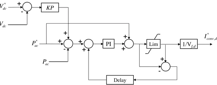
Figure 3.6: Active and reactive outer power controller ... 31
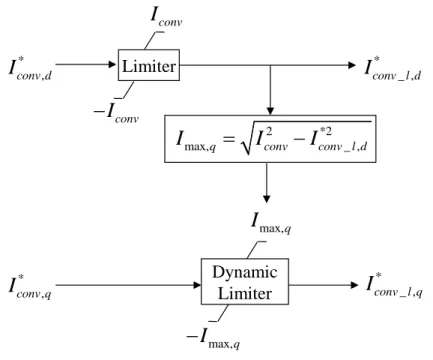
Figure 3.7: Active and reactive current limiter ... 31
Figure 3.8: AC voltage controller ... 32
Figure 3.9: DC voltage controller ... 33
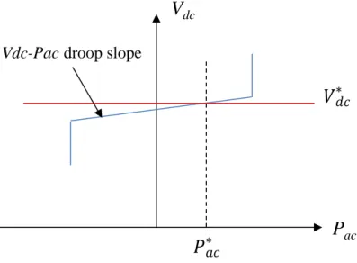
Figure 3.11: Active power controller with dc voltage droop control ... 35
Figure 3.12: Active power controller with frequency droop control ... 35
Figure 3.13: Voltage references and PWM triangular carrier waveforms for a 2L VSC ... 37
Figure 3.14: Voltage references and PWM triangular carrier waveforms for a 3L VSC ... 37
Figure 3.15: Detailed MMC topology ... 39
Figure 3.16: MMC sub-module ... 40
Figure 3.17: BCA procedure ... 43
Figure 3.18: CCS control block ... 45
Figure 3.19: CCSC for a 401-Level MMC, CCSC is removed at t=1s ... 46
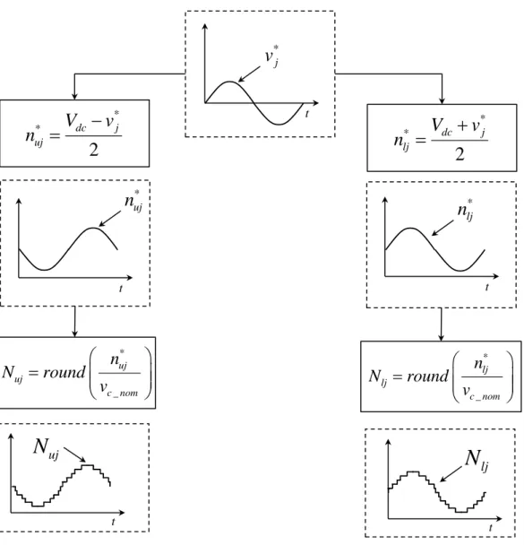
Figure 3.20: NLC modulation control block ... 47
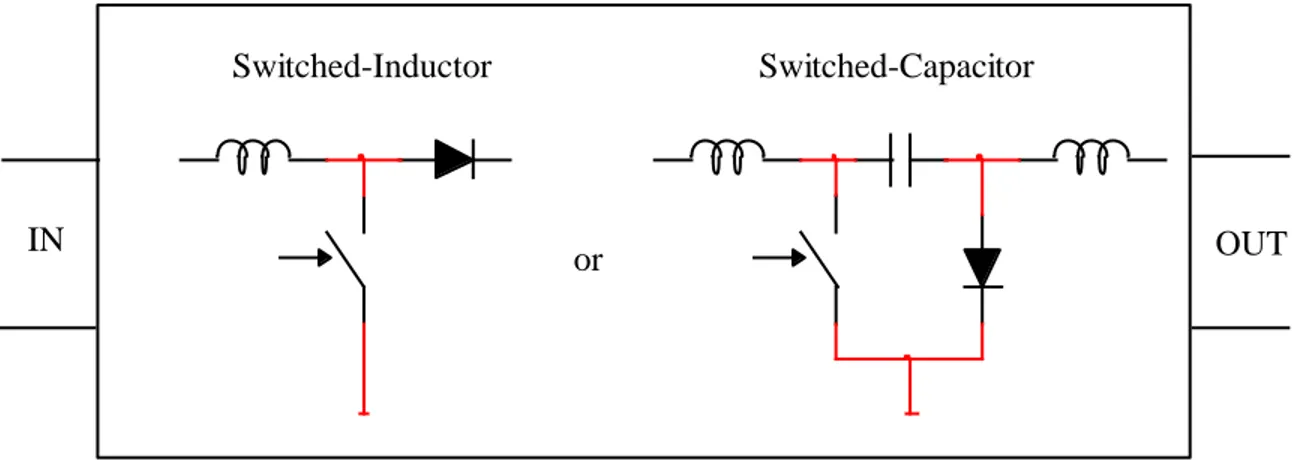
Figure 4.1: Basic switched-inductor and switched-capacitor modules ... 50
Figure 4.2: Current for switched-inductor module during CCM and DCM operation ... 51
Figure 4.3: Voltage and current waveforms for a 2L VSC ... 52
Figure 4.4: Voltage and current waveforms for a 3L VSC ... 52
Figure 4.5: Voltage waveform for 3L VSC during steady-state operation ... 53
Figure 4.6: VSC AVM using algebraic parametric functions in the dq0 frame ... 55
Figure 4.7: AVM model for 2L and 3L VSCs ... 57
Figure 4.8: VSC voltage waveforms for 2L and 3L converters ... 59
Figure 4.9: Switching function circuit model for a 2L VSCs ... 60
Figure 4.10: 2L converter voltage (pu): DML2 (dashed blue line), ASL2 (solid black line) ... 61
Figure 4.11: 3L converter voltages (pu): DML3 (dashed blue line), ASL3 (solid black line) ... 62
Figure 4.12: AC side representation of the AMM ... 65
Figure 4.13: AC voltage (pu) for a 21-level AMM ... 65
Figure 4.15: Equivalent representation of the SM ... 68
Figure 4.16: Converter’s multi-valve arm representation of the MMC ... 69
Figure 4.17: SM circuit representation with simplified IGBT model ... 70
Figure 4.18: IGBT Valve: a) Detailed model with non-linear diodes, b) Simplified model ... 71
Figure 5.1: Test case 1 - VSC-HVDC transmission system using 3L VSCs ... 73
Figure 5.2: Active power (pu) VSC-1 with 20% set-point reduction ... 74
Figure 5.3: Active power (pu) VSC-2 with 20% set-point reduction ... 74
Figure 5.4: Reactive power (pu) VSC-2 with 10% set-point reduction ... 74
Figure 5.5: Reactive power (pu) VSC-1 with 10% set-point change on VSC-1 ... 75
Figure 5.6: DC voltage (pu) Control VSC-2 with 10% set-point change ... 75
Figure 5.7: AC voltage (pu) VSC-2 with 10% set-point change on VSC-2 ... 75
Figure 5.8: DC voltage (pu) VSC-2 - Three-phase fault ... 76
Figure 5.9: AC voltage (pu) VSC-2 - Three-phase fault ... 76
Figure 5.10: AC voltage (pu) VSC-1 - Three-phase fault ... 77
Figure 5.11: Active power (pu) VSC-1 - Three-phase fault ... 77
Figure 5.12: Reactive power (pu) VSC-2 - Three-phase fault ... 77
Figure 5.13: Active power (pu) VSC-1 – Power reversal ... 78
Figure 5.14: AC voltage (pu) VSC-2 – Power reversal ... 78
Figure 5.15: DC current contribution (A) from VSC-1 - Pole-to-pole fault ... 79
Figure 5.16: DC current contribution (A) from VSC-2 - Pole-to-pole fault ... 79
Figure 5.17: Test case 2 – 3L VSC-based MTDC system to integrate off-shore wind generation 80 Figure 5.18: Active power (pu) entering the VSC terminals – Variable wind generation ... 83
Figure 5.19: AC voltage (pu) at INV1 ... 83
Figure 5.21: Loss of Wind Farm 1 ... 86
Figure 5.22: Current (A) from REC1 - DC Pole-to-pole fault on REC1 ... 87
Figure 5.23: Test case 3 – 401-level MMC-HVDC Interconnection between France and Spain .. 88
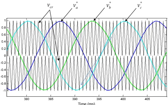
Figure 5.24: AC voltage sources and switching sequence for initialization ... 89
Figure 5.25: Three-phase fault at MMC-2 (Transformer’s HV side) ... 91
Figure 5.26: Active power reversal ... 92
Figure 5.27 DC-fault current contribution (pu) from MMC-1 ... 93
Figure 5.28: MMC ac voltage for a 21-level converter (Transformer secondary) ... 93
Figure 5.29: AC voltages at MMC-1 (pu), phase-a: black, phase-b: blue, phase-c: green ... 94
Figure 5.30: Test case 4 – 21-level MMC-HVDC Interconnection ... 94
Figure 5.31: Three-phase fault at MMC-2 (Transformer’s HV side) ... 97
Figure 5.32: DC-fault current contribution (pu) from MMC-1 ... 98
Figure 5.33 MMC ac voltage for a 21-level converter ... 98
LIST OF NOTATIONS
(1.1) Equation 1.1
[1] Reference 1
2L Two levels
LIST OF ABBREVIATIONS
A Amperes
ac Alternating Current
AVM Average-value Model
BCA Balancing Control Algorithm
CCSC Circulating Current Suppression Control CP Constant Parameter Model
CSC dc
Current Source Converter Direct Current
DLL Dynamic Link Library
DM Detailed Model
DSP Digital Signal Processor EMT Electromagnetic Transients
EMTP-RV Electromagnetic Transients Program, Restructured Version FACTS Flexible ac Transmission Systems
FD Frequency Dependent Line Model GTO Gate Turn-off Thyristor
HV High Voltage
FC Flying Capacitor
HM Hybrid Multilevel
HVDC High Voltage Direct Current IGBT
kV
Insulated Gate Bipolar Transistor kilo-Volt
LVRT LCC
Low-voltage Ride Through Line Commutated Converter MMC Modular Multi-level Converter MTDC Multi-terminal Direct Current
MV Medium Voltage
MVA Mega Volt-Ampere
LIST OF ABBREVIATIONS
MW Mega Watts
NPC Neutral-point Diode-clamped PI Proportional Integral Control
PLL Phase-locked Loop
POI Point of Interconnection
pu Per Unit
SCL Short-circuit Level
SM Sub-module
TD Time Domain
THD Total Harmonic Distortion VCO Voltage Controlled Oscillator VSC Voltage-sourced Converter WB Wideband Line or Cable Model
LIST OF APPENDICES
APPENDIX A CORRESPONDENCE LIST OF FIGURES AND EMTP-RV FILES ... 115
APPENDIX B TEST CASE 1 DATA AND EMTP-RV MODELS DESIGN ... 118
APPENDIX C TEST CASE 2 DATA AND EMTP-RV MODELS DESIGN ... 135
APPENDIX D TEST CASE 3 DATA AND EMTP-RV MODELS DESIGN ... 138
CHAPTER 1
INTRODUCTION
This work presents the development of dynamic averaged models for the accurate and efficient representation of VSC-based HVDC systems technology in EMT programs. The models developed are compared against their detailed representation for validation purposes. The comparison is performed for different VSC-HVDC configurations, converter topologies and applications. This work also presents a detailed description of different VSC-based technologies to introduce researchers into this field. All models developed during this work, including converters topologies, control systems, algorithms, and test cases were developed in the electromagnetic transient software EMTP-RV [1].
1.1 Motivation
Detailed modeling of HVDC systems include the representation of thousands IGBT switches and must normally use small numerical integration time-steps to accurately represent fast switching events. The computational burden introduced by such models highlights the need to develop simplified models that provide similar dynamic and transient behavior. These simplified models are known as mean- or average-value models (AVMs) and their objective is to replicate the average response of switching devices and converters by using simplified functions and controlled sources [2]-[5]. A different AVM concept is the switching function which intends to mimic the high frequency pattern of VSCs allowing the representation of high frequency harmonics [6]-[8]. AVMs have been successfully developed for low power applications in the aerospace and aircraft industry [9], [10] and for wind generation technologies [11]-[13]. However, it is a new trend in high power systems with few applications presented to date including traditional two and three-level VSC-HVDC models in EMT programs [14]-[16]. Reference [17] develops an efficient methodology for simulating MMC systems in EMT-type programs, but it does not model a detailed MMC including a large number of levels and integrated into a large scale transmission system.
The development of accurate and efficient averaged models in EMT programs enables the use of VSC-HVDC technologies integrated into a large grid which corresponds to the main motivation of this research work.
1.2 Contributions of the Thesis
The main objective of this thesis is to overcome the existing computing limitations associated with the detailed modeling of VSC-based HVDC system integrated to large grids. This thesis contributes to the comparison of existing models as well as the development of new averaged models for different VSC technologies. The proposed models are computationally efficient and accurate for the modeling of dynamic and transient events in power systems. The main contributions of this thesis include:
Providing a comprehensive literature review and description of the available VSC-based HVDC technologies, their main component, applications, and comparison with conventional LCC-based HVDC technologies.
Providing comprehensive review and description of the available averaging modeling techniques and methods currently used in power electronic applications as well as exploring their applicability to VSC-based HVDC technologies.
Developing detailed two- and three-level VSC-based HVDC models for different applications in EMTP-RV. These models include converter’s IGBT switches, control and protection systems. They are built with the purpose of validating the proposed averaged models.
Developing detailed MMC-based HVDC models for different applications in EMTP-RV. The models include converter’s IGBT switches, control and protection systems. They are built with the purpose of validating the proposed averaged models. These detailed MMC-based models are the first and only full model benchmark available for model validation and for the use in the studies where averaged models may not be suitable.
Developing efficient averaged models for different VSC-HVDC systems that accurately represent the dynamic and transient behavior of this technology when integrated into large grids. Identifying advantages and limitations of the developed models and their suitability to represent different events in power systems.
Building test cases in EMTP-RV to demonstrate accuracy and performance of the developed models. Test cases include applications such as point-to-point HVDC
terminals, asynchronous HVDC interconnections, and MTDC systems to integrate offshore wind generation.
Comparing different VSC-based technologies and assessing their impact on harmonic content, controllability and fault ride-trough capabilities.
Identifying advantages and limitations of the developed averaged models and studying their suitability to model different events in power systems.
1.3 Methodology
The methodology proposed involves developing detailed models (DMs) in EMTP-RV that accurately represent the actual behavior of VSC-HVDC technologies. These DMs are used to validate the proposed AVMs for different test cases and scenarios. The validation criteria involves comparing systems response to different disturbances such as ac faults, dc faults, changes on power and voltage order set points, power inversion test and other dynamic and transient tests. An initialization technique is proposed to properly set the initial conditions for the time-domain simulation from the multiphase load-flow module of EMTP-RV. The model validation includes the comparison of different variables in time-domain and the comparison of the harmonic content of voltages and currents. The simulation times for different time-steps will be used as a parameter to compare the computing performance and efficiency of the proposed models.
1.4 Thesis Outline
The work presented in this thesis is divided into the following chapters: Chapter 1: Introduction.
Chapter 2: VSC-HVDC Technology: Describes the existing VSC-based HVDC technologies, main components and applications.
Chapter 3: Detailed VSC-HVDC Models: Develops detailed models for VSC-based technologies to be used in the validation of the proposed AVMs.
Chapter 4: Average-value Models for VSC-HVDC Systems: Presents the available methodologies for averaging of power converters used in HV and LV applications, and
develops new averaged models for different VSC-based technologies applied to HVDC transmission. It also presents available simplified methods for efficient modeling of VSC-HVDC systems.
Chapter 5: Dynamic Performance of Averaged Models: Performs a comparison and validation of the averaged models developed against their detailed representation for different VSC-HVDC applications. It also presents the advantages and limitations of the proposed models.
Chapter 6: Conclusions.
The thesis is complemented with appendices (B to E) that include all relevant data required to replicate the proposed models and test cases as well as block diagrams showing the models design developed in EMTP-RV. Appendix A provides a summary list with the correspondence between the figures in this thesis and their respective EMTP-RV files (test cases).
CHAPTER 2
VSC-HVDC TECHNOLOGY
This chapter starts with a brief introduction to HVDC systems followed by a description of the currently available VSC technologies applied to HVDC transmission including main system components, converter topologies, modulation techniques, and control and protection systems.
2.1 Technology Background
Three-phase alternating current (ac) has been the dominant solution for high-power long-distance transmission since the 19th century. The highest commercial voltage level, initially adopted in 1968, is 765kV. Even though few facilities have been built and are operated at higher voltages (1,000kV and 1,200kV), 765kV remains as the highest commercial transmission voltage currently in operation. In ac transmission systems however, the maximum transfer capability may be limited by not only thermal, but also stability and reliability constraints. In order to increase transfer capability, reduce losses and improve stability margins in long transmission lines, series and shunt compensation may be required forcing the use of costly switching substations or building parallel lines. Transfer capability limitations are particularly true for ac transmission involving underground (or submarine) cables where shunt compensation is required causing stability problems in some cases [18].
The development of HVDC transmission technology in 1954 introduced a bright opportunity for long distance transmission due to its superb capabilities and advantages in comparison to ac technologies. Some of the advantages of traditional HVDC over ac transmission are the reduced line losses and cost for comparable distance and capacity. It enables the use of HV cable connections and asynchronous interconnections, and also allows controllability of power flows and voltage which helps improving system stability. Other advantages are the isolation from disturbances of two interconnected systems and the limitation of fault currents and short-circuit levels.
Early development of power electronics for HVDC technologies back in 1939 considered the use of Current Source Converters (CSC) based on mercury-arc valves as it was found to be the most suitable technology to handle large currents. The appearance of the thyristor semiconductor in 1950 had an enormous impact on static-converter technology and it started to
be used in HVDC transmission by mid-1970s. Ever since, LCC technology based on thyristor valves has dominated the HVDC industry.
From 1990 onwards, the VSC technology became economically viable thanks to the development of self-commutated high-power switches, such as GTOs and IGBTs, and the computing power of Digital Signal Processors (DSPs) to generate the firing patterns. HVDC markets involving long-distance high-power transmission are still dominated by traditional thyristor-based HVDC technology, but it is expected that VSC-based technology will replace traditional CSC technology in future due to the fast development of high-power semiconductor, controls systems and protection schemes [19].
VSC-HVDC systems have the capability to rapidly control both active and reactive power independently of each other to keep the voltage and frequency stable. This gives total flexibility regarding the location of the power converters in the system including ac networks having a very low Short-circuit Level (SCL). In contrast to LCC technology, the polarity of the dc link voltage remains the same with the dc current being reversed to change the direction of power flow which eliminates the issue of commutation failures. In addition, VSC-HVDC systems enable black start and emergency support, stabilization of ac grids, fast reverse power flow control, multi-terminal dc implementation, and eliminate the need of ac filters and the use of grounding electrodes due to bipolar operation [20].
Different VSC topologies have been developed in the past 20 years. However, only two have been successfully implemented in HVDC applications: two-level (2L) and multilevel neutral-point diode-clamped (NPC), also known as three-level (3L) [20], [21]. Recent trends on multilevel converters for HVDC include modular multilevel converter (MMC) topology which connects 2L converter modules in cascade to achieve the desired ac voltage [22]-[24]. VSC-HVDC technologies are currently offered by three manufacturers ABB [25], Siemens [26] and Alstom Grid [27].
2.2 VSC-HVDC System Overview
Figure 2.1 shows a high-level representation of a VSC-HVDC terminal for 2L (or 3L) converter topology. A three-phase transformer, with its secondary winding connected in delta to block the zero-sequence voltages generated by the VSC, is used to interface the converter with
the ac system. A series reactor (L) is added between the converter and the transformer for control of active and reactive powers and low-pass filtering of the PWM pattern. It is also used to limit the short-circuit currents. The primary objective of the dc side capacitor (C) is to provide a low impedance path for the turned-off current, to reduce harmonic ripple on the dc voltage (filter) and also to serve as an energy storage device. The control system uses a vector-type control that includes a Phase Locked-loop (PLL), an outer controller and an inner controller. VSCs based on 2L and 3L topologies typically use high-frequency (greater than 1,000Hz) PWM or space-vector modulation [28], [29].
Figure 2.1: 2L (or 3L) VSC-HVDC terminal
New VSC technologies are based on multilevel configurations where 2L sub-modules (SMs) are connected in cascade to form a MMC. The overall configuration of a MMC terminal is presented in Figure 2.2. MMC topologies use a smaller switching frequency helping to reduce converter losses. In addition, filter requirements are eliminated by using a significant number of levels per phase. Scalability to higher voltages is easily achieved and reliability improved by increasing the number of SMs per multivalve arm [30]. The dc capacitors are now included in each SM and the series reactors, used to control the power flow and circulating currents, are
I
dcS
VSC
DC Cable
Yg/∆
L
C
PWM
Inner
Current
Control
Outer P/Q/Vdc
Control
PLL
Ѳ
Ѳ
+
V
dc-abc s
v
v
abcf abc convi
abc convv
embedded in the converter’s phase arms. A Balancing Control Algorithm (BCA) is required to control arm currents and the dc voltage on each SM capacitor [40].
Figure 2.2: MCC VSC-HVDC terminal
2.3 VSC Topologies
VSCs are based on state-of-the-art IGBT semiconductor switches with turn-on/turn-off capabilities and operate at high or low frequencies depending on the topology and modulation technique. The focus of this thesis covers 2L, 3L-NPC and MMC topologies. Other multilevel topologies used in HV and MV applications, such as Flexible ac Transmission Systems (FACTS), are also discussed in this section.
2.3.1 Two-level Converter
The 2L topology has been used in a wide range of power levels including VSC-HVDC transmission. The basic configuration of a three-phase 2L converter is presented in Figure 2.3. Actual systems use packs units grouping several IGBTs switches in series each capable of handling currents between 1-2kA and voltages up to approximately 3kVdc [25]. Features taken into account when designing and specifying IGBT switches are high blocking voltage and turn-off current, low conduction and switching losses, short turn-on and turn-turn-off times, suitable for
S
MMC
VSC
DC Cable
Yg/∆
Modulation
& BCA
Inner
Current
Control
Outer
P/Q/Vdc
Control
PLL
Ѳ
Ѳ
I
dc+
V
dc-abc s
v
v
convabc abc convi
series connection, high dv dt and / di dt withstand capability, good thermal characteristics, and / low failure rates [21].
Figure 2.3: 2L Converter topology
The voltage pattern generated by a 2L converter oscillates between +Vpos and -Vneg (two voltage levels) at a predefined switching frequency. Figure 2.4 shows the 2L converter output and the dominant 50Hz component for a switching frequency ratio of 27 (1,350Hz). The sinusoidal carrier-based PWM produces a voltage waveform with a dominant component plus significant high-order harmonics which are eliminated by means of tuned filter and high-order damped filters.
Figure 2.4: 2L Converter voltage (pu) (blue: 50 Hz component, black: converter output)
+Vpos -Vneg Va Vb Vc S1 S3 S5 S2 S4 S6 + + Time (ms)
Although a VSC feeds fundamental ac current into the system, the converter voltage output is in reality a rectangular waveform. The ac system components connected to the VSC would be exposed to very large step changes in voltage with dv dt levels up to l00kV/µs. This waveform / is unacceptable for direct connection to an ac networks and, if a converter transformer is employed, high-frequency filters are generally used to limit the transformer’s exposure to high
/
dv dt levels. The advantages of the 2L topology are simpley circuitry, small dc capacitors and
footprint, and the same duty is required for all the IGBTs. The main disadvantages are the large blocking voltage required for the IGBTs, crude waveforms forcing the need of filters and high converter losses due to the high switching frequency [21].
2.3.2 Multilevel Converters
Several multilevel converter topologies have been developed in the past for different HV and MV applications. Most typical multilevel configurations are diode-clamped (NPC), flying capacitor (FC) and hybrid multilevel (HM) converters [31]-[33]. Each configuration may contain several levels, but three-levels have been used in HVDC applications and particularly the NPC topology. A brief description of each of them is provided in this section with emphasis in 3L-NPC topology.
2.3.2.1 Neutral Point Diode-clamped Converter
The configuration of a three-phase 3L-NPC converter is presented in Figure 2.5. The voltage pattern generated by a 3L converter has three levels 0, +Vpos and -Vneg oscillating at the switching frequency. Taking phase a in Figure 2.5, when IGBTs S11 and S12 are turned ON, the output is connected to +Vpos and when S12 and S21 are ON, the output is connected to ground. When S21 and S22 are ON, the output is connected to -Vneg. Clamp diodes provide the connection to the neutral point (or ground). From the switching states, it can be deduced that IGBTs S12 and S21 are ON for most of the cycle, resulting in greater conduction loss than S11 and S22, but less switching loss. The dc bus capacitors are connected in series and establish the mid-point neutral voltage (ground in the case of Figure 2.5). In NPC inverters, maintaining the voltage balance between the capacitors is important for the proper operation of the NPC topology.
Figure 2.5: 3L NPC converter topology
Figure 2.6 shows the 3L converter output and the dominant 50 Hz component for a switching frequency ratio of 27 (1,350Hz). Similar to the 2L topology, PWM produces a voltage waveform with a fundamental component plus high-order harmonics which are eliminated by means of tuned and high-order damped filters.
Figure 2.6: 3L Converter voltage (pu) (blue: 50Hz component, black: converter output)
The switching sequence required to generate the voltage pattern is described in reference [31]. The advantages of the 3L-NPC topology are reasonably small dc capacitors needed, lower switch
-Vneg Va +Vpos Vb Vc S11 S12 S21 S22 S31 S32 S41 S42 S51 S52 S61 S62 + + Time (ms)
blocking voltages, small footprint, improved basic ac waveform and relatively low converter switching losses. Among the disadvantages is the inherent difficulty in keeping dc capacitor voltages constant, complex circuitry for large number of levels, the number of added diodes increases rapidly with the number of levels and semiconductor switches have different duties [21].
2.3.2.2 Flying Capacitor Converter
The configuration of a three-phase 3L FC converter is presented in Figure 2.7. Similar to the 3L NPC converter, the voltage pattern generated by a 3L FC converter has three levels 0, +Vpos and -Vneg oscillating at the switching frequency. The switching sequence required to generate the voltage pattern is also described in reference [31].
Figure 2.7: 3L FC converter topology
This topology has no additional diodes, but has additional dc capacitors known as floating (or flying) capacitors. For a three-phase unit, the main dc capacitors are shared by the three phases, but the FC are equal but independent for each phase and are connected to the mid-point connection of the upper and lower diodes on each phase leg. During normal operation, the mean
-Vneg Va +Vpos Vb Vc S11 S12 S21 S22 S31 S32 S41 S42 S51 S52 S61 S62 FC FC FC + + + + +
voltages of the FCs for each phase are charged at +Vpos, where the voltage of the main dc bus voltage is Vdc (Vpos+Vneg). As a result, the voltage across each IGBT switch is only half of the dc-link voltage Vdc. Taking phase a in Figure 2.7, when IGBTs S11 and S12 are turned ON, the output is connected to +Vpos and when S11 and S21 are ON, the output is zero (-Vpos+Vpos). When S21 and S22 are ON, the output is connected to -Vneg. States S11 ON and S22 ON, as well as S12 and S21 ON, are forbidden to avoid shorten the capacitors.
The advantages of the 3L FC topology are similar to the 3L NPC with the difference that all switches have the same duty. With the volume of capacitors largely proportional to the square of their nominal voltages, the disadvantage of this topology is the large footprint incurred by the floating capacitors [21].
2.3.2.3 Hybrid Multilevel Configurations
The generalized structure of a single-phase multilevel inverter with n m-level SMs (or cells) connected in series is shown in Figure 2.8.
Figure 2.8: Generalized topology of a multilevel converter
m-level
cell
m-level
cell
m-level
cell
m-level
cell
V
1V
2V
3V
nVdc
1Vdc
2Vdc
3Vdc
nA phase-to-neutral voltage waveform is obtained by adding up the output voltages of each cell V . It is considered that the output voltage of each cell represents equally spaced levels, n
where the voltage step between two adjacent levels is a function of Vdc . Several topologies of n
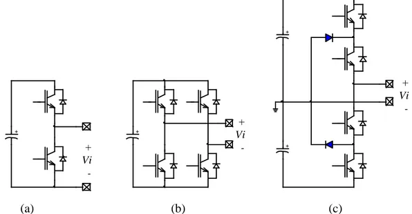
single-phase cells, such as those presented in Figure 2.9, can be connected in series (or cascade) to obtain multilevel waveforms. Full-bridge cells (Figure 2.9b) are usually employed in FATCS devices (STATCOM) because they use a smaller dc bus voltage level, and they present a smaller number of components than half-bridge cells with the same number of levels. On the other hand, full-bridge cells cannot synthesize voltage waveforms with an even number of levels. Although each configuration has its advantages and disadvantages, the unified analysis presented hereinafter does not depend on the arrangement adopted to obtain a given number of levels [32]. A hybrid configuration will combine different level cells in series or different modulation techniques. A multilevel configuration currently used for VSC-HVDC connects two-level cells (Figure 2.9a) in series to form the desired ac voltage configuration and is known as modular multilevel converters (MMC) [23]. As opposed to full-bridge cells, which can generate three Vi voltage levels (+Vdc, 0 and –Vdc), half-bridge cells can only generate two levels (+Vdc and –Vdc, or +Vdc and 0). Half-bridge tree-level cells (Figure 2.9c) can also produce three levels, but they require additional diodes (clamp diodes) which make this topology more onerous for multi-level converter applications.
(a) (b) (c)
Figure 2.9: Sub-modules a) Two-level cell, b) Full-bridge (H-bridge) cell, c) Half-bridge tree-level cell + Vi + Vi + Vi -+ + + +
2.3.3 Modular Multilevel Converters
The MMC topology is a new configuration developed for VSC-based HVDC applications. It connects two-level SMs in series to generate the ac voltage output. Figure 2.10 shows a single-phase MMC configuration including Nu SMs on the upper arm and Nl SMs on the lower arm.
Each SM contains two IGBT switches and a capacitor.
Figure 2.10: Single-phase MMC configuration
Regardless of the sign of the arm current, the voltage v of each SM can be switched to either 0 sm
or to the capacitor voltage v . By switching a number of SMs in the upper and lower arms, the c
voltages V and dc v are controlled. The voltage on the capacitors are periodically measured with a
a typical sampling-rate in the millisecond-range and, according to their voltage value, they are sorted by software. In case of positive arm current (entering into the SM), the required number of SMs with the lowest voltages are switched on (S1=ON, and S2=OFF) and the selected capacitors are charged. When the current in the corresponding arm is negative (going out of the SM), the
SM-1 SM-2 SM-Nu : SM-1 SM-2 SM-Nl : Ls/2 ia va Ls/2 Sub-Module C S1 S2 vsm + -+ -vc Vdc Idc Multi-valve Arm
number of SMs with highest voltages are switched on. By using this method, continuous balancing of the capacitor voltages is guaranteed. The MMC configuration typically includes redundant SMs, meaning a defective SM can be replaced by a redundant SM in the arm by control action without mechanical switching. This results in an increased safety and availability for this configuration [34].
The converter reactor L has two key functions: S
Three-phase MMCs connect the multi-valve arms in parallel on the dc side. As the generated dc voltages on each arm cannot be exactly the same, balancing currents will appear between the individual phase arms. The converter reactors help damping these balancing currents to a very low level and make them controllable by means of appropriate methods.
The reactors substantially reduce the effects of faults arising inside or outside the converter. As a result, unlike in previous 2L and 3L VSC topologies, current rise rates of only a few tens of amperes per microsecond are encountered even during critical faults such as a short circuit between the dc terminals of the converter. These faults are swiftly detected and, due to the low current rise rates, the IGBTs can be turned off at absolutely uncritical current levels.
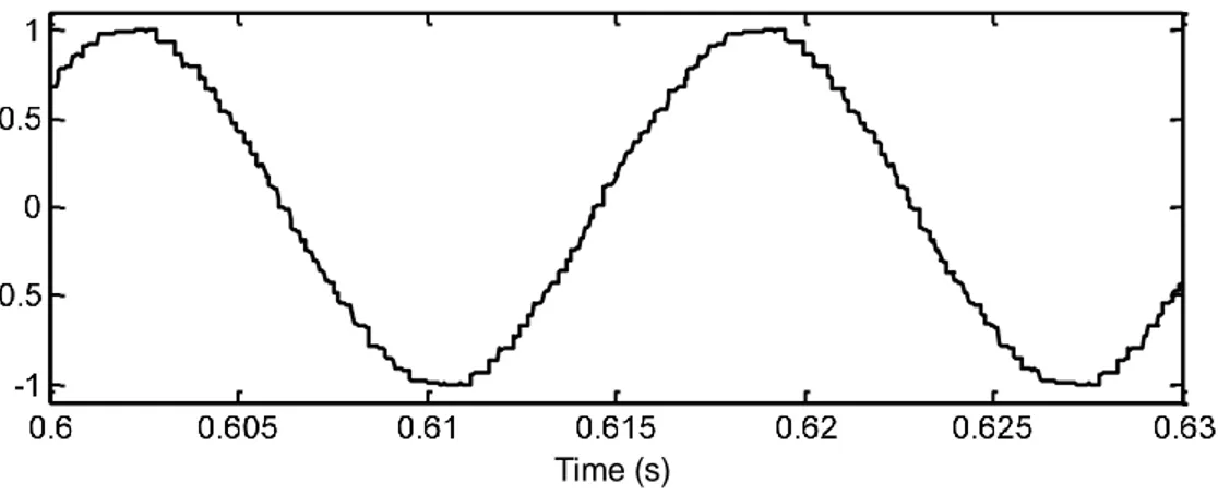
The voltage pattern generated by a MMC is a staircase waveform where each step corresponds the SM voltage (or capacitor voltage) v . Figure 2.11 shows the ac voltage waveform for a c
detailed 21-level MMC (20 SMs per multi-valve arm).
Figure 2.11: AC voltage (pu) for a 21-level MMC
It can be noted that the higher the number of SMs, the lower the harmonic content and the need for filtering. An actual MMC-based HVDC systems of 400MW will include 200 SMs per multi-valve arm on each phase. A larger system in the range of 1,000MW will contain 400 SMs per multi-valve arm forming what is known as a 401-level MMC. These large systems will not require any filter on the ac side of the converter as the voltage output will be almost a perfect sinusoidal waveform as it will be demonstrated later on. The typical dc voltage for an actual 201- and 401-level MMC is 200kV and 320kV, respectively [30], [34].
A detailed description of a three-phase MMC topology and its control system is provided in section 3.2 of this thesis.
2.4 Filtering Requirements
VSCs based on two- and three-level topologies are usually operated using sinusoidal PWM technique to control the fundamental frequency and the modulation index of the ac voltage. As previously shown in Figure 2.4 and Figure 2.6, the converter’s voltage output includes a fundamental frequency plus high frequency components. Elimination of harmonics in VSCs is achieved by the use of ac filters. The series reactor will also help to filter the harmonic content. A typical VSC-HVDC scheme will include a couple of tuned filters plus a high frequency filter. The filters are tuned at the switching frequency and twice the switching frequency. The transformer connection is delta on the secondary side (converter side) in order to remove third-order harmonics. Depending on the filter performance requirements, the filters size will vary between 10-30% of the rated converter’s capacity [20]. The requirements for 2L and 3L VSC filter are as follows:
1 1.0% h h U D U (2.1) 2 1.5% 2.5%, h h THD
D (2.2)where D is the individual voltage harmonic distortion and THD is the Total Harmonic h
Distortion measured at the Point of Interconnection of the VSC-HVDC system. These are voltage quality performance measures. There is also a telephone influence factor (TIF) that is used as an indication of the expected telephone interference. Filters are also added on the dc side along with
smoothing reactors where the converter capacitor is installed in order to suppress harmonics. Cables on the dc side may run close to telephone lines causing interference, therefore, additional filtering may be required to minimize telephone interference from dc cables.
The high dv dt in the switching valves may cause a high frequency noise which should be / prevented from propagation to the rest of the system and outside the converter facilities. Mitigations measures are implemented at the valve level by using dumping circuits, but radio interference (RI) filter capacitors and reactors connected between the ac bus and earth are typically used.
MMC-based VSC-HVDC systems using a large number of levels (above 100) do not require ac filters to improve voltage quality as the converter output will be an almost perfect sinusoidal waveform. Harmonic content analyses for different converter levels will be studied in a further section of this report.
2.5 DC Link
The dc link in 2L and 3L VSCs is formed by the storage capacitors and the dc cable or overhead line, respectively. The primary objective of the dc side capacitor is to provide a low-inductance path for the turned-off currents and also to serve as an energy storage device. The capacitor also reduces the harmonics ripple on the direct voltage. Disturbances in the system (e.g. ac faults) will cause dc voltage variations. The ability to limit these voltage variations depends on the size of the dc side capacitor. A storage capacitor provides the corresponding VSC with a smooth dc voltage of a fixed polarity. To achieve maximum use of the power semiconductors of the VSC, the capacitor needs to be connected to the converter by a low inductive path. The size of the capacity is chosen according to the maximum dc voltage ripple tolerated [20]. It should be noted that a dc capacitor is not required in MMC configurations as the storage capacitor is now embedded in the converter’s SM. This particularity will reduce the stress on the IGBT switches due to dv dt variations. /
A VSC-HVDC system cannot change voltage polarity. Power reversal is achieved by changing the direction of dc current instead. This enables the use of extruded dc cables, which are an attractive alternative to self-contained oil filled or mass impregnated paper insulated cables as used for conventional thyristor-based HVDC systems. The cable length is not limited as it would
be in case of ac transmission systems. VSC-HVDC systems use land or submarine polymer cables similar to XLPE ac cables, but with a modified polymeric insulation. Cable data for dc cables can be found in [20].
For the purpose of this thesis, the dc cables used in EMTP-RV are modeled using a wideband frequency dependent cable model [35] in order to study both dynamic and transient events on the dc side of the VSC-HVDC link.
2.6 Control System
A high level overview of the control system for a 2L (or 3L) and a MMC-based VSC was presented in section 2.2. The basic control scheme uses a vector control (Figure 2.1) which includes an outer controller that generates the current references in the dq0 synchronous rotating frame to the inner controller [36], [37]. The purpose of the inner current controller (or ac current controller) is to allow the (active and reactive) current through the series reactor and the transformer to be controlled. The synchronous frame rotates at the frequency obtained from the PLL which synchronizes the converters voltage with the ac voltage. The inputs to the PLL are the ac voltages of the three-phases at the Point of Interconnection (POI). The current references to the inner controller are obtained from the outer controller (or current-order controller) whose inputs are the active and reactive reference power, or the rms voltage on the converter filter. The dc voltage is also controlled through the outer controller by a current reference order. A voltage-dependent current order limiter provides control to keep the ac filter voltage within its upper and lower limits. The tap changer of the converter transformer is controlled to keep the voltage modulation ratio (m ) within acceptable limits. The frequency can be controlled in cases where v
VSC-HVDC system is supplying a passive (no sources or active elements) network [38]. The reactive power control includes an ac voltage override block intended to maintain the ac voltage within acceptable pre-defined limits. The active power control, in turn, includes a dc voltage limiter that overrides the active power control in order to maintain the dc voltage within an acceptable range.
Multilevel (three levels or higher) converters present the problem of having the neutral-point voltage subject to fluctuations due to the irregular charging and discharging cycle of the upper and lower dc capacitors. This unbalance may cause excessive overvoltages on the
switching devices and on the dc capacitors. The dc-voltage regulation method used in this thesis controls the zero-sequence current and adds a zero-sequence signal to the voltage reference of the PWM [39]. MMCs on the other hand, need to balance the second-harmonic circulating currents generated by unbalances in the phase arms as well as the dc capacitor voltage at each SM. This is achieved by using a circulating current suppression control (CCSC) and a balancing control algorithm (BCA), respectively [30]. More details on the origin and mitigation of voltage and current unbalances generated in MMCs are provided in sections 3.2.1.1 and 3.2.1.2, respectively. Under unbalanced network conditions or grid disturbances, voltage ripple is introduced into the dc link. To mitigate this effect, a control strategy that decouples positive and negative sequence inner-current loops can be implemented. This control strategy improves the dynamic response of the VSC-HVDC system as shown in [44]. The following chapter provides a more detailed description of the control system developed and used in this thesis for different VSC topologies.
2.7 Protection System
The main purpose of the protection system is to promptly remove the VSC components from service in the event of a fault. The main protection device in a VSC-HVDC system is the ac breaker which disconnects the converter and transformer from the grid removing dc current and voltage. Depending on the type of fault and converter technology, the clearing actions may go from transient currents limitation by temporary blocking the valves and control pulses to permanent blocking of the VSC and ac breaker tripping. The transient current limiter stops sending pulses to the IGBTs of the faulted phase or all three phases when overvoltage protection is enabled and is re-established once the fault is cleared. A permanent blocking, whereas, will send a turn-off signal to all the IGBT switches and they will stop conducting.
VSC-HVDC systems based on MMC technology include, in addition to the ac breaker, a press-pack thyristor on each SM in parallel to S (Figure 2.10) which is used to protect the anti-2 parallel diodes exposed to high currents from dc faults. Once a dc fault is detected and the IGBTs are blocked, the fast-recovery free-wheeling diodes, which have low surge current withstand capability, are exposed to damaging currents for a few cycles. The thyristor is fired during the fault allowing most of the current to flow through the thyristors and not through the diodes until the ac breaker opens [24]. Press-pack thyristors have a high capability to withstand surge currents
which make them useful in conventional LCC-HVDC applications and their use in VSC-HVDC applications will make this technology suitable for applications involving overhead transmission lines.
2.8 VSC-HVDC Applications
VSC-HVDC systems have the advantage of independently controlling active and reactive power and voltage which make this technology suitable for a number of applications including grid performance and operations support. Examples of applications include parallel interconnection of ac and dc systems where VSC-HVDC link can help damping oscillations in the ac systems [20]. The advantage of this technology for system restoration is considerable in terms of voltage and frequency stability during black start. VSC-HVDC will enable applications requiring asynchronous connections between two systems either back-to-back or by means of dc transmission links. This advantage increases when the connection requires the use of underground or submarine cables such as in VSC-based MTDC systems used to integrate offshore wind generation [45]-[48]. Future in-feed to dense urban cities are an attractive application of VSC-HVDC systems due to their capability to use cable systems and also to control voltage and frequency at the VSCs [38].
CHAPTER 3
DETAILED VSC-HVDC MODELS
This chapter describes the detailed VSC-HVDC models (and mathematical formulation) developed in EMTP-RV for the validation of the proposed AVMs. It starts with the first generation of VSC technologies based on 2L and 3L converters to continue with the latest generation based on MMC technology.
3.1 Two- and Three-level Converter Models
In the detailed two- and three-level converter topologies, described in sections 2.3.1 and 2.3.2, the IGBT switches are modeled using an ideal controlled switch, two non-ideal (series and anti-parallel) diodes and a snubber circuit, as shown in Figure 3.1a. The non-ideal diodes are modeled with nonlinear resistances using the classical V-I curve of a diode whose characteristic can be adjusted according to manufacturer data (Figure 3.1b). This model offers several advantages as it can accurately replicate the nonlinear behavior of switching events accounting for both switching and conduction losses. Six and twelve IGBT valves were modeled for the two- and three-level converters, respectively. Therefore, the RLC snubber circuit must be calibrated to account for losses in the case of an actual VSC system where several IGBTs are connected in series and parallel in order to withstand the design voltage and current.
(a) (b)
Figure 3.1: a) IGBT valve representation, b) Diode V-I curve
It should be noted that partial differential equations could be used to develop a lumped circuit for the IGBT valve. In [61], a complex IGBT sub-circuit is proposed and compared against a finite element model. This complex representation can accurately represent switching losses; however, they require extremely small time-steps (nanoseconds) as the switching event occurs over a very
Current (A) V o lt a g e ( V )
Entered characteristic plot
n p g + + R L C + n p g + RLC
p
n
g
p
n
g
short period of time. These types of models are not usually used for power system simulations due to excessive computing time requirements and are outside the scope of this thesis.
3.1.1 Control System
Two- and three-level based VSCs use the same control system approach which is known as vector control [36]. The method calculates a voltage time area across the equivalent reactor L
(or voltage drop) which is required to change the current from present value to the reference value. The vector control operates in the synchronous rotating dq0-frame and its main components are the phase-locked loop (PLL), inner and the outer control blocks. The inner controller regulates the converter ac voltage (and current over the series reactor) that will be used to generate the modulated switching pattern and the outer controller regulates the current references needed to control the main VSC parameters such as power flow, ac voltage and dc voltage. Using vector control, the active and reactive power (or voltage) can be independently controlled by regulating the currents in the dq0-frame [36].
3.1.1.1 Synchronous dq0 Reference frame
The use of a rotating dq0-frame allows decoupled control of active and reactive power flows. A set of three-phase voltages in the abc-frame can be transformed into two-dimensional
complex frame by the Clark transformation [49].
1 1/ 2 1/ 2 3 , 2 0 3 / 2 3 / 2 a b c v v v v v (3.1)
where v ,a v , and b v are the three-phase voltages in the abc frame, and vc and v are the corresponding voltages in the frame (Figure 3.2a). The dq0transformation is given by the Park transformation [49] using the reference frame in Figure 3.2b.
(a) (b) Figure 3.2: Reference frames: (a) Stationary and (b) rotating dq0
cos( ) sin( ) sin( ) cos( ) d q V v V v (3.2)
The angle is the transformation angle and is equal to t , where is electrical frequency in rad/s of the ac system under consideration. The direct (T ) and inverse (T ) 1 abc dq 0 transformation matrices are defined as follows:
cos( ) cos( 2 / 3) cos( 2 / 3) 2
sin( ) sin( 2 / 3) sin( 2 / 3) 3 a a d b b q c c v v V v v V v v T (3.3) 1 cos( ) sin( ) cos( 2 / 3) sin( 2 / 3) cos( 2 / 3) sin( 2 / 3) a d d b q q c v V V v V V v T (3.4) 3.1.1.2 Phase-Locked Loop
When a VSC terminal is connected to an active ac system, the frequency and phase must be detected at a pre-defined reference point in order to synchronize the converter and control system accordingly. This action is performed by the PLL circuit which synchronizes a local oscillator with a sinusoidal reference input coming from the system’s ac voltage. This ensures that the local oscillator is at the same frequency and in phase with the reference voltage input.
α
v
cv
bβ
α
d
q
β
v
aφ
θ
v
aφ
The local oscillator is a voltage controlled oscillator (VCO). The block diagram of the PLL is shown in Figure 3.3, where Vq is the q-axis voltage coming from the abc dq 0 transformation of the voltage reference and o is base system frequency. The component Vq is selected as it is proportional to sin( ) and sin( ) for small values of the angle .
Figure 3.3: Phase-locked loop block diagram
When the converter is connected to a passive system, such as a load connection or a wind farm, the frequency is fixed to o by the PLL and only the frequency oscillator is required to generate the angle . This control approach will be used to implement a voltage/frequency VSC controller for MTDC systems integrating offshore wind generation.
3.1.1.3 Inner Control in the dq0 frame
The voltage drop equation of the reactance L in Figure 2.1 is computed as follows: ( )
( )t ( )t R ( )t Ld t dt
abc
abc abc abc conv
f conv conv
i
v v i (3.5)
where vectors abc conv
v and vabcf are the converter and filter’s instantaneous voltages for the three phases abc . The vector abc
conv
i represents the three instantaneous line currents through the reactance L. It is assumed that the reactance L has a small resistance represented by R. If the voltage drop equation in (3.5) of is transformed into the dq0 frame (using matrix T ), the following equations are derived:
,
, , , ,
conv d
conv d f d conv d conv q
dI V V L RI LI dt (3.6)
k
i*∫
k
p+
V
qk
vp+
o∫
+
+
VCO
,
, , , ,
conv q
conv q f q conv q conv d
dI
V V L RI LI
dt
(3.7)
where Vconv d, and Vconv q, are the direct- and quadrature-axis representation of the converter’s voltage, and Vf d, and Vf q, are the direct- and quadrature-axis representation of the voltage at the converter’s filter. Likewise, Iconv d, and Iconv d, represent the current through the inductance L in the dq0 reference frame.
These equations are the base of the inner control loop for a balanced network. The active (P ) ac
and reactive (Q ) power equations on the ac side of the converter are derived from the dq0 axis ac
components for voltage (vabcf ) and current (iconvabc ) as follows:
, , , , 3 2 f d ac ac conv d conv d f d V P jQ I jI jV (3.8) , , , , 3 ( ) 2 ac f d conv d f q conv q P V I V I (3.9) , , , , 3 ( ) 2 ac f d conv q f q conv d Q V I V I (3.10)
The power on the dc (P ) side is given by: dc
dc dc dc
P V I (3.11)
where V and dc I are the dc-side converter’s voltage and current, respectively. Assuming there is dc
no zero-sequence component (due to the transformer converter’s delta connection), a three-phase voltages (vector vabc) can be decomposed into positive- (vector vabc+ ) and negative-sequence (vector vabc ) components when the network is unbalanced [44], [51].
( )t + ( )t - ( )t
abc abc abc
v v v (3.12)
Applying the T matrix transformation with the corresponding rotating angle ( for positive sequence and for negative sequence), the positive- and negative-sequence components are derived in the dq0 rotating frame: