HAL Id: hal-02089105
https://hal.archives-ouvertes.fr/hal-02089105
Submitted on 3 Apr 2019
HAL is a multi-disciplinary open access
archive for the deposit and dissemination of
sci-entific research documents, whether they are
pub-lished or not. The documents may come from
teaching and research institutions in France or
abroad, or from public or private research centers.
L’archive ouverte pluridisciplinaire HAL, est
destinée au dépôt et à la diffusion de documents
scientifiques de niveau recherche, publiés ou non,
émanant des établissements d’enseignement et de
recherche français ou étrangers, des laboratoires
publics ou privés.
SYSTEMES AUTOMOBILES CRITIQUES
SECURITAIRES
Nataliya Yakymets, Morayo Adedjouma
To cite this version:
Nataliya Yakymets, Morayo Adedjouma. METHODOLOGIE ET ENVIRONNEMENT POUR LA
CONCEPTION A BASE DE MODELES DE SYSTEMES AUTOMOBILES CRITIQUES
SECURI-TAIRES. Congrès Lambda Mu 21 “ Maîtrise des risques et transformation numérique : opportunités
et menaces ”, Oct 2018, Reims, France. �hal-02089105�
METHODOLOGIE ET ENVIRONNEMENT POUR LA CONCEPTION A BASE DE
MODELES DE SYSTEMES AUTOMOBILES CRITIQUES SECURITAIRES
METHODOLOGY AND FRAMEWORK FOR MODEL-BASED DESIGN OF
SAFETY-CRITICAL AUTOMOTIVE SYSTEMS
Nataliya Yakymets, Morayo Adedjouma
Commissariat à l'énergie atomique et aux énergies alternatives (CEA)
CEA LIST, Saclay, Nano-INNOV, F-91191, Gif-sur-Yvette
[email protected]
,
[email protected]
Résumé
Ce papier présente une méthodologie et un environnent outillé pour la conception et l’analyse de sureté de systèmes automobiles critiques selon une approche d’ingénierie dirigée par les modèles. Cette méthodologie adresse quelques limitations identifiées dans les méthodes et outils existants pour l’analyse de sûreté fonctionnelle. La méthodologie exploite la co-ingénierie matériel et de sureté pour définir une méthode de développement compositionnelle compatible avec la norme ISO26262. La méthodologie permet de définir des systèmes sur par conception en couplant les processus de sûreté et de développement. La méthodologie est implémentée dans un outil de modélisation appelé Sophia, offrant un environnement de développement graphique pour la conception et l’implémentation de systèmes matériels.
Summary
The paper gives an overview of existing methods and tools for safety analysis and presents a methodology and framework for design and safety analysis of critical automotive systems based on model-based approach. It exploits hardware/safety co-engineering to define a compositional development method compatible with ISO26262. The methodology allows obtaining safe-by-design automotive systems by coupling development and safety processes. The methodology is implemented in a modeling framework, called Sophia, offering a graphical development environment for hardware system design and implementation.
1. Introduction
In automotive domain with the advent of automated driving, systems are safety-critical as failures or hazardous decisions about the environment may lead to accidents that cause human lives. Due to the safety-criticality nature of such systems, system and safety engineers are prone to follow safety standards and guidelines (e.g. ISO26262). The increased complexity of systems, and their new constraints, imposes to R&D teams, of different industries, to adopt new methodologies and their associated tools.
In this context, model-based engineering is a promising approach capable to integrate various methods and tools for safety analysis into the single system modeling environment, to customize this environment to the automotive domain and to provide elaborated traceability links across safety analysis process. In practice, however, the tool support of model-based safety analysis (MBSA) and traceability of safety data across this process is not well-elaborated.
To cope with this issue, we propose a methodology and a framework, called Sophia, to couple MBSE and MBSA for automotive systems. The methodology extends our prior work described in [1][2] to the context of automotive systems and complies with ISO26262 safety standard. The associate Sophia framework automates the proposed methodology and improves the traceability of system and safety data during MBSE and MBSA of automotive systems at the early phases of their life-cycle. Sophia is based on Papyrus 1 UML modeler. It includes safety meta-models and profiles compatible with ISO26262, model transformation and fault tree generation plug-ins, tools for HARA (Hazard Analysis and Risk Assessment), FMEA (Failure Mode and Effects Analysis) and FTA (Fault Tree
1 https://www.eclipse.org/papyrus/ 2 https://www.fides-reliability.org/
Analysis), basic integration with FIDES2 tool, document
generation plug-ins.
We apply the methodology on an Adaptive Cruise Control (ACC) system to illustrate its applicability and effectiveness to support system and safety co-engineering with regard to ISO26262. Using this case study, we apply the proposed method and show how to use Sophia environment to describe possible effects of failures of ACC and to display various results including FME(C)A tables, generated fault trees, etc.
2. Related Works
According to [3], MBSA is “an approach in which the system and safety engineers share a common system model created using a model-driven development process”. The integration of any classical safety analysis method into MBSE environment requires three main steps [2]:
• System model creation; • Safety annotation and modeling; • Safety analysis and generation of results. The system model can be created using languages such as UML (Unified Modeling Language)3, SysML (System
Modeling Language)4, or domain specific languages like
RobotML which extends UML to describe architectures and behaviors of mobile robots. Then the system model is extended with the safety concepts and relations. This could be done either by using safety profiles [2][4][5][6] or by translating the system model into formal or safety languages for further analysis [7][8]. The latter case needs additional efforts to study the semantics of both languages and to implement the bridges between tools. Once the model has been annotated with safety data, it can be analyzed using MBSA tools offering one or many methods for safety analysis.
3 www.uml.org/ 4 http://sysml.org/
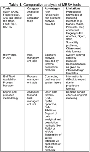
MBSA tools fall into three categories: (i) analytical and simulation tools; (ii) risk management tools; (iii) process management tools. Table 1 lists examples of MBSA tools and shows their main advantages and limitations.
Table 1. Comparative analysis of MBSA tools
Tools Category Advantages Limitations
xSAP, SAML, Figaro toolset, AltaRica toolset, Hip-Hops, FaultTree+, CAFTA Analytical and simulation tools Rich functionality and profound analysis provided Professional knowledge of modeling methods (e.g., Markov chains, Petri nets, etc.) and formal languages like AltaRica, Figaro, SMV; Scalability problems; Often closed data formats RiskWatch,
PILAR Risk managem ent tools Extensive analysis provided by informal description methods System is never explicitly modeled; Recommendatio ns given as informal design templates IBM Tivoli Availability Process Manager Process managem ent tools Connecting business and system layers Information is difficult to export due to proprietary formats Sophia and proposed methodology Analytical tool and Risk managem ent tool Open data formats (UML, SysML, openPSA, SMV, AltaRica); Support of both analytical and description methods (like FMEA or HARA) Traceability of safety artefacts via application of several methods Demand certain efforts during first modeling
Examples of analytical and simulations tools are xSAP[7], SAML [8], Figaro toolset [9], AltaRica toolset5,
Hip-Hops[10], FaultTree+6, CAFTA7. Despite rich functionality
and profound analysis provided by those tools, many of them require professional knowledge of modeling methods (e.g., Markov chains, Petri nets, etc.) and formal languages like AltaRica, Figaro, SMV, etc. which is a barrier for widespread utilization. Among other issues are scalability problems (in particular, increasing number of states during a static modeling) and closed data formats that makes it difficult to reuse and/or export obtained safety models, libraries and results. Tools like AltaRica or xSAP require reverse engineering to build system models.
RiskWatch8 or PILAR9are the tools implementing various
risk management methodologies. Those tools are exclusively qualitative, and based on various tabular structures filled by informal description methods. The running system is never explicitly modeled. All proposed recommendations for risk mitigation remain in the area of general and informal design templates.
The process management tools such as IBM Tivoli Availability Process Manager10aim to connect the business
layer with the system layer. Information obtained with those tools is difficult to reuse and/or export, as it is based on proprietary tools/protocols.
There are also some ongoing initiatives and projects working on safety certification platforms (e.g. the European
5 https://altarica.labri.fr/
6 https://www.isograph.com/software/reliability-workbench/ 7 https://www.controlsdata.com/civil-aero/cafta
8 http://www.riskwatch.com/ 9 www.pilar-tools.com/en/tools/pilar/
AMASS11 initiative), however there is still a lack of tooled
aid that would help to cover a complete conformance to safety standards. Matlab Simulink supports ISO26262 but it is usually used at later stages of development. In the context of AUTOSAR and EAST-ADL, [14] proposes a methodology for early safety analysis to comply with ISO26262. Sophia and the associated methodology provides both an analytical and risk management framework that covers all stages of development and safety analysis from specification to design. It provides a fluent and integrated flow with several safety analyses techniques depending on the development progress. The design and safety artefacts are traced to each other in a coherent manner and defined in open data formats that facilitates their usage in external tools. The important effort introduces for the deployment of the methodology at the first time for a project is rapidly amortized during next iterations of the project or other future projects thanks to the reusability inherent to a model-based approach.
3. Paper Contribution
We propose a methodology for the design of safety-critical automotive systems based on model-based approach. We exploit hardware/safety co-engineering to define a compositional development methodology compatible with ISO26262. This allows obtaining safe-by-design automotive systems by coupling development and safety processes. Although ISO26262 provides only generic recommendations on which safety related work-products and results should be issued during the development and analysis of automotive safety-critical systems, it does not specify the particular processes and how to get those results. In order to tackle this limitation, the proposed methodology specifies the development and safety analysis flows based on recommendations given in ISO26262. There may exist dependencies between work-products recommended by ISO26262, which can slow down the hardware development. Therefore, an innovative and efficient way to implement the ISO26262 recommendations is to turn to hardware/safety co-engineering and parallelize steps of the proposed flows when possible. The advantage of such an approach is that safety steps do not block hardware development steps, and conversely.
The methodology is implemented in a modeling framework, called Sophia, offering a graphical development environment for hardware system design and implementation.
The proposed methodology and framework provide a support for safety engineers working in automotive domain by formalizing, synchronizing and semi-automating hardware development and safety analysis activities recommended in ISO26262.
4. Methodology
The methodology shows how to conduct safety analysis from the early steps of hardware (HW) development. ISO26262 describes a “reference phase model for the product development at the hardware level”.
The inputs for the proposed methodology are 1) system description including requirements, functional and system architecture, and 2) safety analysis results from HARA (Hazard Analysis and Risk Assessment), FTA (Fault Tree Analysis), FMEA (Failure Mode and Effects Analysis), obtained at the prior phases of system development life-cycle such as concept definition and product development at the system level.
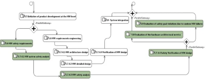
In order to harmonize the proposed co-engineering methodology with ISO26262, we map its main steps to the clauses of the standard as shown in Figure 1. Below the
10
https://www.ibm.com/software/products/fi/tivoliavailabilityprocessmanag er
steps are prefixed with the appropriate clauses from ISO26262 (e.g. 5.7.4.1 is corresponding to clause 7.4.1 of part 5 of ISO26262). The methodology defines the following steps:
- 5.5 Initiation of product development at the HW level. In this step, we determine and plan the functional safety activities to perform during the individual steps of hardware development.
- 5.6 HW requirements engineering and (synchronized with) 5.6 HW safety requirements. During these steps, the design and safety requirements of the hardware system are specified and analyzed by hardware engineer and safety
engineer respectively. These two steps refer to the clause 5.6 of ISO26262.
- 5.7.4.1 HW architecture design and (synchronized with) HW system safety analysis. The hardware system architecture is specified. This architecture is then annotated with safety artifacts defining failure modes, its causes and effects, as well as hardware dysfunctional behavior. Once the architecture is extended with safety artifacts, the preliminary hardware system safety analysis is conducted. This analysis includes such semi-automated methods as FMEA, FTA and formal safety property verification. If new hazards are introduced during these steps, HARA must be also conducted.
Figure 1. Proposed hardware/safety co-engineering methodology.
- 5.7.4.2 HW detailed design and (synchronized with) 5.7.4.3 HW safety analysis. During the hardware detailed design, the hardware system is refined into a detailed design for implementation. This step corresponds to clause 5.7.4.2 of ISO26262. The preliminary safety analysis made in the previous step is extended during the hardware safety analysis according to the detailed specification of the hardware components. This step refers to clause 5.7.4.3 of ISO26262. In addition to the semi-automated FMEA, FTA, and, optionally, HARA, the manual analysis of safe, single- and multiple-point faults should be conducted. The later identifies the safe, single- and multiple-point faults, provides the evidence of the effectiveness of safety mechanisms to avoid residual and latent faults, and gives their diagnostic coverage.
- 5.7.4.4 Verification of HW design and (synchronized with) 5.7.4.4 Safety Verification of HW design. During these steps, we verify the hardware design for compliance and completeness with respect to the requirements, including the safety requirements. For the latter, verification is supported by safety analyses. These two steps refer to the clause 5.7.4.4 of ISO26262.
- 5.8 Evaluation of the hardware architectural metrics and (synchronized with) 5.9 Evaluation of safety goal violations due to random HW failures. In these steps, we verify the architectural metrics and residual risk for compliance with the ASIL of the safety goals. Using safety analyses, we evaluate the effectiveness of the architecture of the system to cope with the random hardware failures as well as the effectiveness of the dedicated measures defined for hardware to avoid violations of the safety goals due to random hardware failures. These steps refer to the clause 5.8 and 5.9 of ISO26262.
- 5.10 HW integration.
The proposed co-engineering methodology allow us to conduct our hardware development in parallel with safety analysis with respect to ISO26262. By parallelizing both concerns in a co-engineering process, the hardware development steps are not blocked by the safety steps.
5. Safety Engineering ADLs
In our methodology, there is only one Safety Engineering concern associated with one stakeholder, the Safety Analyst. The ADLs are UML profiles dedicated to the following aspects of safety analysis:
- Safety Requirement Engineering. This ADL describes a taxonomy of safety requirements compatible with ISO26262 and proposes an extended list of requirement properties. - Process Management. This ADL defines evolution of system architecture through its live-cycle by introducing such concepts as system feature, function, component, hardware and software along with corresponding allocation relationships.
- Hazard Analysis and Risk Assessment, HARA. This ADL describes the safety concepts related to HARA from ISO26262.
- Failure Mode and Effect Analysis, FMEA. This ADL describes safety concepts related to FMEA, criticality FMEA and diagnostic FMEA.
- Fault Tree Analysis, FTA. This ADL describes safety concepts related to qualitative and quantitative FTA. - Formal Safety Property Verification. This ADL describes safety concepts related to system dysfunctional behavior (Failure State, Failure Event, Failure Transition, etc.) and property verification expressed in CTL logic. The use of this ADL allows model translation to SMV language for further formal analysis with NuSMV tool.
Each profile has its equivalent viewpoint, e.g. FMEA_Viewpoint, FTA_Viewpoint.
Table 2 gives the mapping between steps defined by our hardware/safety co-engineering methodology and the viewpoints of domain-specific ADLs described above. In this paper, the mapping focuses on viewpoints because they are the main elements in our ADLs that answer the engineering concerns.
The proposed methodology and ADLs are implemented in Sophia. It is a Papyrus-based tool for model-based safety analysis developed in CEA. Sophia provides a single environment for model-based system and safety
engineering and includes ADLs and tools for safety requirement engineering, process management, HARA, FTA (including probabilistic calculations based on FIDES), FMEA, formal safety property verification in CTL.
Table 2. Mapping of the proposed method to
domain-specific ADLs
Proposed method (Fig. 1) Viewpoint HW Dev. Safety
Analysis SysML Sophia ADLs
5.6 HW
req. eng. SysML Require-ment diagram 5.6 HW safety req. eng. Safety Requirement Engineering Viewpoint 5.7.4.1 HW architectu re design SysML Block definition & internal block diagrams Process Management Viewpoint: Hardware System Design 5.7.4.1 HW system safety analysis HARA, FMEA, FTA, Formal safety property verification Viewpoints 5.7.4.2 HW detailed design SysML Block definition & internal block diagrams Process Management Viewpoint: Hardware System Design 5.7.4.3 HW safety analysis HARA, FMEA, FTA, Formal safety property verification Viewpoints 5.7.4.4 Verificatio n of HW design HARA, FMEA, FTA, Formal safety property verification Viewpoints
6. Case Study
We demonstrate our proposed approach by applying it on an Adaptive Cruise Control (ACC) System. The ACC is a well-known automotive system that allows a vehicle’s cruise control to adapt the vehicle’s speed to the traffic environment. The driver of the host car with ACC system can set the speed and clearance mode. The ACC uses a radar attached to the front of the vehicle to detect whether preceding vehicle are moving in the path of the host car with ACC system. If there are no preceding vehicles, the system maintains driver selected speed. When preceding vehicles shows up, the system may automatically apply braking, control throttle or shift gear to adapt the vehicle speed and maintain driver selected clearance without intervention of the driver. We get inspired by the ACC system specifications defined in [15] to design and analyze the ACC system according to the different viewpoints of our approach.
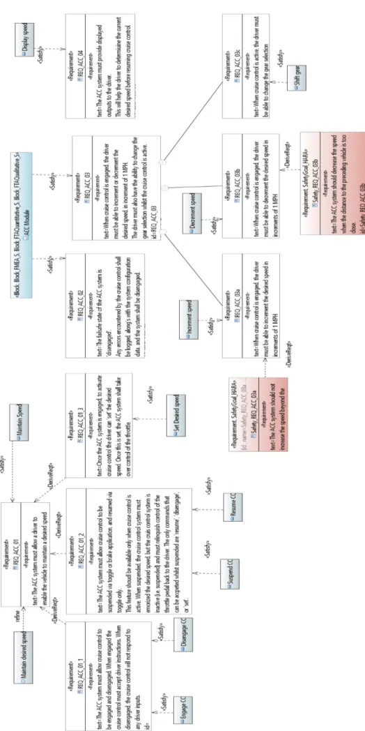
6.1. Safety Requirement Engineering viewpoint. We first
capture the functional requirements of the ACC system. The requirements specify functionalities of the ACC system, so they are linked to functional component representing the system. In Figure 2 that presents some ACC functional requirements in a Requirement diagram, let consider the requirement “REQ_ACC_03”. This requirement is satisfied by the component “ACC module”, and its refinement in several subrequirements REQ_ACC_03a, REQ_ACC_03b, REQ_ACC_03c, are satisfied by the system function “Increment speed”, “Decrement speed” and “Shift gear” respectively. These requirements are enriched with safety requirements developing the counter measures identified as we performed the safety analyses of the system.
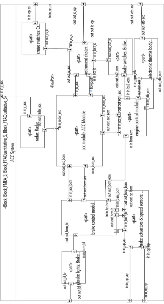
6.2. Process Management viewpoint. We use SysML
diagrams to describe the vehicle feature including the usage scenarios, the ACC system architecture, etc. Figure 3 shows an outline of the ACC system components at a high level that we model with a Block Definition Diagram. The core part of the ACC system is the ACC module. The ACC module processes data information receives from the radar component that scans the road and determines the speed of the preceding vehicles. The ACC module sends a signal to Brake Control module in case of braking need. The Engine Control Module and Electronic Throttle Control are used to control the vehicle speed by increasing or
decreasing throttle injection. The cruise switches component have several buttons that allow the driver to command ACC functionalities and to set selected speed and clearance. The Instrument cluster is a panel in front of the driver that process the cruise switches and send them to the ACC and Engine Control Modules. The instrument cluster also display information regarding the ACC system state to the driver. The Brake switches component are used to deactivate the cruise control operation. The Brake lights component allows illumination of the stop lamps during automatic braking from the ACC module request. The Brake actuators & Speed sensors component embodied the sensors and devices such as the brake pedal, the accelerator pedal, etc. All the signals between the components are transmitted over communication bus, such as Controller-Area Network (CAN). Figure 4 shows the hardware design of the ACC with the interconnecting interfaces between those components, using Internal Block Diagram. Those components are trace to the functional requirements captured in the Safety Requirements viewpoint. Whenever the architectural element are refined, they are also trace back to some refined requirements.
6.3. HARA viewpoint. The Hazard analysis and risk
assessment is carried out based on the usage scenarios and the main functionalities of the system (including its architecture and interfaces if available) according to ISO26262. Hence, the hazard analysis take into account the models defined in the Safety requirements and Process management viewpoints.
The analysis first specifies the dangerous situations by determining the operational scenarios that, in combination with some environmental, driving and operating conditions (for example, driving high speed, ACC engaged, etc.), may lead to accidents. An example of operational situation that can lead to a dangerous situation is “the ACC system being active when the vehicle is driving on highway at medium speed, following a preceding vehicle”. The analysis also introduces the malfunctions and associated hazards leading to these accidents and establishes the resulting hazardous events in relation to the elicited dangerous situations in which they can occur.
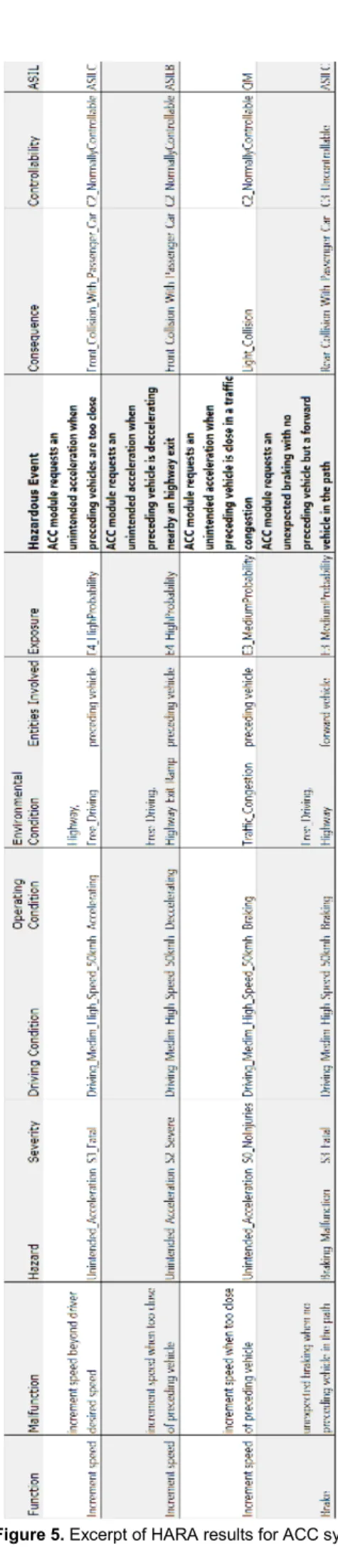
Figure 5 shows an excerpt of the HARA table defines for the ACC system where each line describe a Hazardous event and its related information.
Let consider the ACC function “Increment speed” to maintain desired distance with the preceding vehicle about the first two lines in Figure 5. Examples of malfunction that can happen with regard to this function is “the ACC system increases the vehicle speed when it is too close of the preceding vehicle” and “the ACC system increases the speed of the vehicle beyond the desired speed set by the driver”. The generic hazard “Unintended acceleration” can be associated with these malfunctions.
The resulting hazardous event as defined by ISO26262 are combination of the hazard and the operational situation, i.e. “ACC module requests an unintended acceleration when preceding vehicles are too close”, which situation ended in a crash accident with severe to fatal injuries to people involved. The hazardous events are automatically classified according to an ASIL level based on specified exposure level (E) of operational scenarios, controllability (C) of these scenarios in the presence of the hazardous events and the severity (S) assigned to the resulting accident. In our example in Figure 5, our hazardous event is evaluated at ASIL C (E=E4, C=C2, S=S3).
Finally, the analysis allows the determination of safety goals for the hazardous events to prevent an unacceptable risk level of those events or reduce their impact. These goals are meant to be a refinement of the ACC functional requirements defined in the Safety Requirement Engineering viewpoint. Figure 2 shows few safety requirements that refine the ACC functional requirements.
Figure 3. Top level architecture of ACC system.
Hence, for our example of hazardous event, we define the following safety goals REQ_ACC_03a: “The ACC system should not increase the speed beyond the desired speed set by the driver”, and REQ_ACC_03b: “The ACC system should decrease the speed when the distance to the preceding vehicle is too close”.
All information participating in the accident scenario are defined as model elements that are reusable from one viewpoint to another, e.g. the set of operating conditions are derived from the vehicle and ACC states, the malfunctions are specified for all functions that satisfied the functional requirements of the system. Note that as generic, the hazards can be used from a reusable hazard list library. The nature of injuries are also coming from a predefined list corresponding to the injury category described in the ISO 26262 standard. Sophia environment provides dedicated features (diagrams, palette, custom views, etc.) to define these artefacts and visualize them in different formats (tables, pdf, etc.). Figure 5 shows an excerpt of the HARA summary table defined for the ACC system, exported in excel from the framework.
6.4. FMEA viewpoint. The FMEA complements the HARA
in order to determine better the correctives actions to implement to meet the safety objectives previously defined. This analysis use as input the usage scenarios, the system architecture of the system, as well as the results of the HARA model elements (accidents, malfunctions, hazardous events, accidents, etc.) and their properties (severity, asil, etc.). The analysis helps determine the effects and criticality of single basic causes of failure modes at component level up till system level and. The FMEA artefacts are traced to hazardous events and accidents previously identified in HARA analysis. To perform the analysis, our method proposes to identify for each component, the different failures modes that can lead to its loss or unwanted behavior. For each failure mode, we must identify the effects (at component, system and customer levels) and their initial and final severity, the causes and their initial occurrences, as well as the preventive actions and final occurrences. Sophia environment offers automatic safety annotations of system components, modelling of FMEA artefacts (causes, effects, preventive actions), criticality analysis, generation and display of FME(C)A tables within the model, and visualization of results in different formats (table, pdf, excel, etc.).
Figure 6 shows the FMECA table defines for the ACC system where the different Failure modes and associated artefacts are traced to its components. We identify different failure modes as over speed, under speed, loss of braking, unexpected braking, etc. The causes of the failure modes range from external to software and hardware related. Example of such causes are missing input signal, communication bus fault, delayed operation of the signal, no current to actuators, incorrect data received from radar,
etc. The failure modes can lead to different effects until the crash of the vehicle at customer level that correspond/trace to the accident identified in HARA. Some preventive actions are elicited to either avoid the failure modes apparition, or reduce severity of its effects, e.g. a system architecture modification to not allow cruise activation or to deactivate cruise mode when the braking system is on failure. The preventive actions can also be as simple as warning implementation as e.g. display information to the driver on the panel about the failure mode. The preventive actions are turned into safety requirements to make the hardware design safer. These new set of safety requirements are trace to the safety goals elicited during HARA.
6.5. FTA viewpoint. The FTA analyzes the propagation
within the architecture of identified failures modes. The analysis allow probability calculations of the basic feared events and the resulting minimal cut sets that can lead to accidents. The goal is to identify and prevent the multiple failure points. Specifically, a top event is analyzed at the component level by combining a series of lower-level events using Boolean logic. The FTA module of Sophia environment allows the automatic annotation of models with safety properties and the definition of reliability expressions at the ports of the component units of the system architecture. This annotation makes it possible the generation of the fault trees and to define different qualitative and quantitative analyzes of the architecture. The results of these analyzed are exported in different files. A visualization of FT trees is also provided.
7. Conclusion and Further Work
We present the methodology and framework for coupling model-based system engineering, safety analysis at the early phases of development life-cycle of automotive systems. The methodology aims to fill the gap between system modeling and safety assessment activities by formalizing, synchronizing and semi-automating hardware development and safety analysis activities recommended in ISO26262.
The proposed methodology is implemented in the modeling platform which supports a common system model for system and safety engineers, by using UML profile mechanisms in Papyrus. This allows integration of all artefacts related to safety analysis in the same system model, interface customization, highlighting different results within one modeling environment and reuse this information for further reliability studies.
We study an example of the Adaptive Cruise Control system to illustrate our approach. We model a hardware architecture of the system and then apply our methodology to illustrate its applicability and effectiveness to support system and safety co-engineering with regard to ISO26262.
The obtained results helps us to identify critical components of the Adaptive Cruise Control system and to propose changes in the architecture to reduce its overall criticality level.
As further activities, we want to provide a graphical monitoring support of the ISO26262 standard to assess progress in achieving its recommendations and produced the required work products. As such, we are working on an automatic translation of textual parts of ISO26262 to the formal process description language BPMN (Business Process Modeling Notation) that includes also guidance with cheat sheets. The model of the standard integrates our methodology and it is linked with the tool support. This will allow to link each step of development and safety engineering process with the ISO26262 recommendations from one side and issued safety artefacts from another side.
8. References
[1] N. Yakymets, S. Dhouib, H. Jaber, A. Lanusse, “Model-Driven Safety Assessment of Robotic Systems,” IEEE/RSJ Int. Conf.on Intelligent Robots and Systems, IROS’2013,Tokyo, Japan.
[2] Nataliya Yakymets, Matthieu Perin, Agnes Lanusse, “Methodology and Framework for Model-Driven Multi-Level Safety Analysis of Critical Systems”, Proc. of the 9th Annual IEEE International Systems Conference (SysCon), Vancouver, Canada, 2015, pp. 570 – 577. [3] M.P. Heimdahl, A. Joshi, M. Whalen, “Model-based
safety analysis: final report,” NASA Technical Report, 2005.
[4] Jean-Francois Castet, Magdy Bareh, Jeffery Nunes, Steven Jenkins, and Gene Lee. "Fault Management Ontology and Modeling Patterns", AIAA SPACE 2016, AIAA SPACE Forum, (AIAA 2016-5544).
[5] Hecht, M., Dimpfl, E. and Pinchak, J. (2015), Using SysML to Automatically Generate of Failure Modes and Effects Analyses. INCOSE International Symposium, 25: 1357–1372.
[6] Geoffrey Biggs, Takeshi Sakamoto, Tetsuo Kotoku. A profile and tool for modelling safety information with design information in SysML. Software & Systems Modeling, vol. 15, issue 1, pp 147–178, 2016. [7] B. Bittner, M. Bozzano, R. Cavada, et al., The xSAP
Safety Analysis Platform. CoRR abs/1504.07513 (2015), https://es.fbk.eu/tools/xsap.
[8] M. Gudemann, F. Ortmeier, “A Framework for Qualitative and Quantitative Formal Model-Based Safety Analysis,” In Proc. 12th IEEE High Assurance Systems Engineering Symposium (HASE'10), pp. 132-141, 2010.
[9] M.Bouissou, "Automated dependability analysis of complex systems with the kb3 workbench: the experience of edf r&d," in Proceedings of the International Conference on Energy and Environment, 2005
[10] S. Sharvia, Y. Papadopoulos, “Integrating model checking with HiP-HOPS in model-based safety analysis”, Reliability Engineering & System Safety, Vol. 135, March 2015, pp. 64–80.
[11] Jeremie Guiochet. Hazard analysis of human--robot interactions with HAZOP—UML. Safety Science, Elsevier, 2016, 84.
[12] Askarpour M., Mandrioli D., Rossi M., Vicentini F., “SAFER-HRC: Safety Analysis Through Formal vERification in Human-Robot Collaboration,” Computer Safety, Reliability, and Security. SAFECOMP 2016. Lecture Notes in Computer Science, vol 9922. Springer, Cham.
[13] Naveen Kumar, Komal, J. S. Lather. Reliability analysis of a robotic system using hybridized technique. Journal of Industrial Engineering International, pp 1–11, 2017.
[14] P. Cuenot, C. Ainhauser, N. Adler, F. Meurville. Applying Model Based Techniques for Early Safety Evaluation of an Automotive Architecture in Com-pliance with the ISO 26262 Standard, ERTS’14.