Application Development in
A Knowledge-Based Conceptual Generator
by
Johanes Chandra Sugiono
B.S., Northeastern University (1992) Boston, MA
Submitted to the Department of Civil and Environmental Engineering in partial fulfillment of the requirements for the degree of
Master of Science in Civil and Environmental Engineering
at the
MASSACHUSETTS INSTITUTE OF TECHNOLOGY
February 1995
@
Massachusetts Institute of Technology 1995. All rights reserved.Author... ... ... Department of Civil and tnvxronipental Engineering
-
December 8, 1994
C ertified by ... ... ... ...
Duvvuru Sriram, Senior Research Scientist, Thesis Supervisor
-I
r)
A ccepted by ... ... .. ... . ...
Joseph M. Sussman Chairman, Departmental Committee on Graduate Students
Application Development in
A Knowledge-Based Conceptual Generator
byJohanes Chandra Sugiono
Submitted to the Department of Civil and Environmental Engineering on December 16, 1994, in partial fulfillment of the
requirements for the degree of
Master of Science in Civil and Environmental Engineering
Abstract
Engineering design process can be decomposed into several stages. One of the most important stage is conceptual design. Conceptual design provides a strong foundation on which the subsequent design stages are executed. CONGEN (CONcept GENerator), a conceptual design agent provides the capability of integrating knowledge which supports the decision making process, as well as a constraint management satisfaction scheme and a visualization tool to help the designer overcome the limitations of traditional CAD systems. In implementing a design application on top of CONGEN, the structural engineering domain is chosen. Structural engineering design provides a good testbed for application development in CONGEN. The existing knowledge and the preliminary computational support provides challenge to CONGEN as the choice platform.
The contribution of this study is to provide complete documentation support for CON-GEN. This helps the users to successfully implement various applications. It starts by in-troducing the users to the basic concepts and structure of CONGEN and gradually moves toward the development of a Cabin Design application utilizing all the capabilities of CON-GEN.
The issues addressed by this thesis are the formulation of CONGEN basic concepts in answering the challenges of conceptual design implementation, the step-by-step approach in developing the application, and lastly, the evaluation of CONGEN capabilities and its future directions. In addition, this thesis also supports the basic premise that CONGEN is a flexible system for developing design applications independent of any knowledge domain.
Thesis Supervisor: Duvvuru Sriram Title: Senior Research Scientist
Acknowledgments
Firstly, I sincerely thank God for the chances that He has given me throughout my life. The works that He has done for me has been amazing and miraculous.
I would like to thank my advisor, Professor Duvvuru Sriram for his support throughout this study and giving me another shot for studying something totally new.
Thank you to Prof. Robert Logcher for the discussions on developing the application. His quest for new ways and directions in Information Technology makes me believe that the changes are only for the better future.
I would like to thank Jen Diann Chion for his assistance in developing the knowledge base in an area I've never known before.
I also express my gratitude to Prof. Jayachandran, Gorti Sreenivasa-Rao, and Murali Vemulapati for the discussions and support in finishing this thesis.
I also would like to express my thanks to PT. PAL INDONESIA for giving me the opportunity to study at M.I.T. for two years and supporting me financially during my years in USA.
Lastly, to all my KMK friends, the ones who believe or even do not believe in my finishing this thesis, thank you all for the prayers.
Dedications
To my ever-loving, supportive parents and sisters in Indonesia. Thanks for believing in me. For without them, I would not be here at all. It is my turn to take care of you all now. To my beloved grandparents, I love you both. You are the best grandparents in the world!!
To my guiding light and inspiration. Diany Pranata. I would not have finished this thesis if I never met you here. You made me believe in miracles. We did it!
Contents
1 Introduction 15
1.1 M otivation . . . 17
1.2 O bjectives . . . 18
1.3 Roadmap of the Thesis ... 18
2 Background 21 2.1 Object Oriented Concepts ... 21
2.2 DICE Project .. . . . .. .. . . . .. . . . .. .. . . . .. . . . 23
2.3 C O SM O S . . . 25
2.4 G N OM ES . . . .. . . . . .. . . . 26
2.5 CO PLA N . . . 27
2.6 CON G EN .. .. . . . . .. . . . .. . . . . .. . . . 28
2.7 How to Use this Documentation ... 28
2.8 Sum m ary .. . . .. 31
3 CONGEN Application Concepts 32 3.1 CONGEN - CONcept GENerator ... 32
3.2 Knowledge and Design Concepts . . . . 34
3.3 CONGEN Product Concepts ... 37
3.4 CONGEN Process Concepts ... 38
3.5 Integrating the Concepts ... 40
CONTENTS
3.7 Sum m ary . . . .
4 Tutorial I: Getting Familiar with CONGEN 4.1 Starting a CONGEN Session ...
4.2 File M enu . . . .. . .. . .. .. . 4.2.1 CONGEN Application Management System . . 4.3 Knowledge Menu ...
4.4 Specifications Menu ... 4.5 Execute M enu ... 4.6 Browsers M enu ...
4.7 Sum m ary .. ... ... .. ... ... ... ...
5 Tutorial II: A Simple CONGEN Application 5.1 The Notation ...
5.2 The Problem ... 5.3 The Implementation ...
5.3.1 Preparation ...
5.3.2 Creating a new application ... 5.3.3 Creating classes and rulesets ... 5.3.4 Making the application ...
5.3.5 Creating goals and plans for the application . . 5.3.6 Executing the Synthesizer . . . .
5.3.7 Executing the Geometric Modeler (GNOMES) and show the geometry 5.4 Other Solutions to the Problem ...
5.5 Sum m ary . . . .
6 Tutorial III: Building a Box
6.1 The Problem . . . . 6.2 The Implementation ...
6.2.1 Preparation . . . . 6.2.2 Creating a new application .. . . .
46 . . . . 46 . . . . 48 . . . . . 51 . . . . 53 . . . . 57 . . . . 58 . . . . 60 . . . . 64 65 . . . . 65 . . . . 66 ... 67 . . . . 67 . . . . . 68 . . . . . 69 . . . . 75 .... . . 75 . . . . . 77
CONTENTS
6.3 6.4
6.2.3 Creating classes and rulesets ... 6.2.4 Making the Application ...
6.2.5 Creating goals and plans for the application . . . . 6.2.6 Executing the Synthesizer . ...
6.2.7 Executing the Geometric Modeler (GNOMES) and Other Solutions to the Problem ... ...
Summary ... ... . . ... show . . . . . . 92 . . . . . . 97 . . . . . . 98 . . . . . 102 the geometry 108 . . . 109 . . . 112
7 Tutorial IV: CABIN DESIGN Application
7.1 The Problem . . . .... 7.1.1 Process Flow ... 7.1.2 Knowledge Acquisition ... 7.1.3 Vocabulary ... 7.1.4 Geom etry . ... ... ... ... ... . 7.1.5 A nalysis . . . . 7.2 The Implementation ... 7.2.1 Preparation ... ... .. ... ... ... . 7.2.2 Creating a new application . . . ... 7.2.3 Creating classes and rulesets . . . . 7.2.4 Making the Application . . . .... 7.2.5 Creating goals and plans for the application 7.2.6 Executing the Synthesizer . . . ..
114 114 115 118 121 124 129 130 130 131 132 140 140 153 159 160 7.2.7 Executing GNOMES and displaying the geometry
7.3 Summary ... ... 8 Summary and Future Work
8.1 Summary ... . . ... 8.2 Future Work ... ... . . . ... A REFERENCE MANUAL
A.1 Reserved Keywords ... ...
164 S164 S167 176 S176 ___
:r
CONTENTS
A.2 Available Methods ... A.3 Dynamic Methods ... A.4 Application Script . ...
B COSMOS Knowledge Base Rule in CONGEN B.1 COSMOS Rule Grammar ...
B.1.1 Explanation of the Grammar B.1.2 Comment Block . . . . B.1.3 Rule . ... B.1.4 Rule Name ... B.1.5 Rule Priority . . . .. B.1.6 Condition Block . . . . B.1.7 Test Expression . . . . B.1.8 Arithmetic Expression ... B.1.9 Example of Condition Block. B.1.10 Action Block . . . ... B.1.11 Example of Action Block . . B.1.12 Inline Comment Block . . . .
B.2 Helpful hints in building and running rules in CO SMOS
C Installation, Configuration & Troubleshooting C.1 Installation . . ...
C.1.1 How to Obtain CONGEN . . . . C.1.2 Requirements . ...
C.1.3 Pre-installation . ...
C.1.4 Compiling CONGEN . . . . C.1.5 Environment Variables .
C.1.6 Database Environment V
D Tutorial 2 & 3 Listings
D).1 TUTORIAL 2 - SIMPLE SLAB . . . . .
. . . . .. . . ariable . . . . 198 . . . . . . . . . . 19 S : ::: 177 179 183 185 185 186 187 187 187 188 188 188 189 189 190 191 191 192 195 195 195 195 196 196 196 197
CONTENTS
D.1.1 Main Listing of the rulefile Tutorial_2.rul = Alternative 1 -One Goal, One Plan rulefile . . . . . . . . ..
D.1.2 Alternative 2 - One Goal, One Plan, Two Subgoals D.2 TUTORIAL 3 - BOX APPLICATION
D.2.1 Main Listing . . . .. ... D.2.2 Alternative -tut3long.rul . . .
E CABIN DESIGN elements E.1 Cabin Artifact Vocabulary
E.1.1 Structural Member Su perclass .
. ,. .
E.1.2 Joint . . .. . . . . . . E.1.3 Linear Members . . . E.1.4 Area Members .... E.1.5 Beams ... E.1.6 Columns . . . . E.1.7 Piers . . . . .. . .. . E.1.8 Truss-member . . . . E.1.9 Truss-system . . . . . E.1.10 Slabs . ... ... ... E.1.11 W alls ... E.1.12 Walliopening ... E.1.13 Strip-footing . . . . . E.1.14 Matifound ... E.1.15 Spreadfound ... E.2 Examples of CABIN Rulefiles
E.2.1 cabineff.rul ... E.2.2 set-columns.rul . . . . E.2.3 set-girders.rul . . . . . E.2.4 set girderseff.rul . . .
E.2.5 set southwalleff.rul . . . .
213 . . . . . . . . . . 213 . . . . . . . . . . 213 . . . . . . . . .. . 214 . . . . . . . . . . 215 . . . . . . . .. . 216 . . . . . . . . .. . 2 16 . . . . .. . . . . . . 2 17 . . . . . . . . .. . 2 18 . . . . . . . . . . 219 . . . . . . . . . . 220 . . . . . . . .. . 221 . . . . . . . . .. . 223 . . . . . . . . .. . 223 . . . . . . . . 224 .. . . . . . . .. . 225 . . . . . . . . .. . 226 .. . . . . . . 228 . . . . . . . . . .. . 228 . . . . . . . . 229 . . . . . . . . . . 235 . . . . . . . . . . 236 . . . . . . . . . . 238 198 200 202 202 209 ---. .
CONTENTS
E.2.6 set _foundation-eff.rul . E.3 CABIN calculation rulefiles . E.3.1 Loading.rul . . . . E.3.2 Beam.rul ...
E.3.3 Column.rul . . . . E.3.4 Slab.rul . . . .. E.4 CABIN script ...
E.4.1 createcabin.c . . . . . . . . . 241 . . . 261 . . . . . . 261 ... 264 . . . . . . 266 . . . . . . 267 . . . . 269 . . . . . . 269
---. ---. ---. ---.
.. . . .
... . . ....
. .
..
.. . . ....
.
.. .
..
...
~.
.. . . .
.
. . . . ....
..
List of Figures
1-1 The organization of this thesis ... ... ... .. ... . .. ...
2-1 The roadmap of this chapter ... .. ... ... ... 2-2 The collaborative product development environment . . . .
3-1 The organization of this chapter. ...
3-2 The architecture of CONGEN and the supporting modules within its frame-w ork . . . . 3-3 The integrated CONGEN's product a:
3-4 CONGEN Application Architecture.
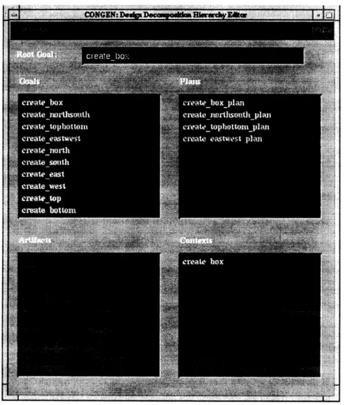
The roadmap of this chapter. . CONGEN Main Console ... QUIT Warning window ... NEW Application window .... RETRIEVE Application window. DELETE Application window. . Design Decomposition Hierarchy GOAL EDITOR window .... Product Knowledge window. . CLASS EDITOR window... Rule List Selection window .... Rule File EDITOR window ....
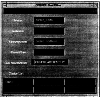
EDI• • • nd process concepts . . . . . 35 . . . . 4 5 . . . . 4 7 . . . . 48 . . . . 48 . . . . 49 . . . . . 49 . . . . 50 TOR window. . . . . 54 . . . . 55 . . . . 55 . . . . 56 . . . . 57 . . . . 5 7 4-1 4-2 4-3 4-4 4-5 4-6 4-7 4-8 4-9 4-10 4-11 4-12
LIST OF FIGURES
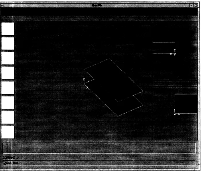
4-13 Specifications EDITOR window . ... 4-14 GNOMES Geometric Modeler window ...
4-15 Synthesizer window. ... ...
4-16 GNOMES Geometric Modeler window with top and bottom covers of an application. ... ...
4-17 Artifact Browser window. ... 4-18 Rulefile Browser window. ... 5-1 The roadmap of this chapter. ...
5-2 Creating Tutorial2 application ... ...
5-3 Slab Attributes entered. ...
5-4 CLASS EDITOR (PUBLIC) window after attributes have been entered.. 5-5 createslab rule in the RULE EDITOR window. ...
5-6 Saving createslab Rule in the RULE EDITOR window ... 5-7 createslab Goal shown. ...
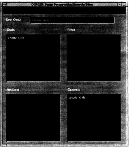
5-8 DDH Editor after everything has been entered and saved ... SYNTHESIZER window after finished creating the Slab.. XTERM window after finished creating the Slab... GNOMES showing the Slab geometry .... ... Other alternative solution to Tutorial_2 ... Other alternative solution to Tutorial2 ...
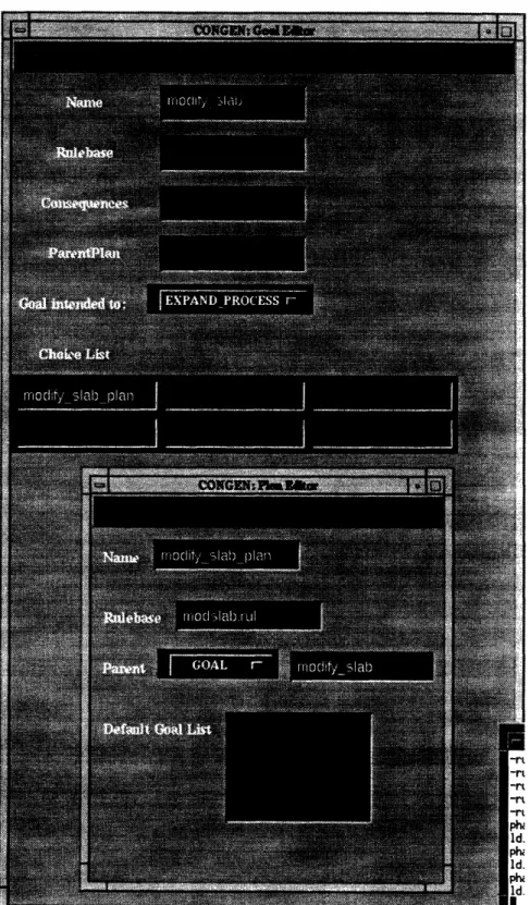
The technique of combining a dummy plan and a goal to f The roadmap of this chapter . ... ... Tutorial 3 Application structure. ... . . . . . ..... Slab3 class attributes ... .... ... Assembly class attributes .. .... ... Assembly class Artifact Defaults . ... ... The createbox root goal for the application . . . . The createiboxplan for the application. . ...
ire a ruleset. . .. . . . . . . 88 . . . . . . . . 90 .. . . . . . . 93 . . . . . . . . 94 . . . . . . . . 95 . . . . . . . . 98 . . . . . . . . 99 5-9 5-10 5-11 5-12 5-13 5-14 63-1 6-2 6(3-3 6(3-4 6(3-5 6-6 6- 7
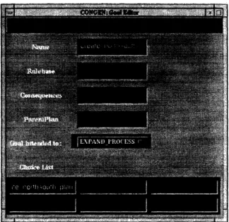
--LIST OF FIGURES
The create.northsouth goal for the application . . . . .. The create-northsouth-plan for the application . . . . .. The create-north goal for the application . . . . .. The DDH EDITOR window after everything has been entered . . . .. The SPECIFICATION EDITOR window after everything has been entered.
The SYNTHESIZER window with the created instance of Assembly... The SYNTHESIZER window after the top cover slab has been created . .
6-8 6-9 6-10 6-11 6-12 6-13 6-14 6-15 6-16 6-17 6-18 6-19
The roadmap of this chapter. ... Cabin Architectural plan. ...
Cabin Design Application structure . . . . .. The New Structural Member hierarchy ...
The abstraction of GAB geometry classes in CONGEN . . . Cabin class expanded without using the Cabin-part - notice
. . . . 115
. . . . 116
. . . . . 119
. . . 122
. . . 127
all the parts linked to Cabin class filling the window. 7-7 Cabin class expanded using the Cabin-part. instances shown in the preceding figure . . 7-8 Cabin class attributes ... 7-9 The create-cabin goal description . . . .. 7-10 The set beam-column-grid goal description.. 7-11 The setcolumn goal description ... 7-12 The setbeams goal description ... 7-13 The set-girders goal description . . . .. 7-14 The set-supporting beams goal description. . 7-15 The set-trusssys goal description . . . .. Cabin_part contains all the . . . . . 134 . . . . 135 . . . 142 . . . . . 143 . . . . 143 . . . 144 . . . . 144 . . . . . 145 . . . . . 145 The XTERM window showing all the rulefiles fired . . . ..
The SYNTHESIZER window after every path has been traversed. The DDH EDITOR window after every path has been traversed. The DDH BROWSER window after create-south.Slab3 is pressed. The GNOMES window with the box ...
100 101 101 102 103 104 106 S107 S107 S108 S109 S110 7-1 7-2 7-3 7-4 7-5 7-6 133 ..
LIST OF FIGURES 7-16 7-17 7-18 7-19 7-20 7-21 7-22 7-23 7-24 7-25 7-26 7-27 7-28 7-29 7-30
The settrusses goal description . . . .. The set-purlins goal description . . . .. The setwalls goal description . . . .. The set-north-wall goal description . . . .. The set-southwall goal description . . . .. The set-east-wall goal description . . . .. The set-westwall goal description . . . .. The setfoundation goal description . . . .. The cabin design plan description . . . .. The set beamcolumngrid plan description. . . . The set -beams-plan description . . . .. The setwalls-plan description. ...
The set trusssys-plan description . . . .. The Synthesizer first pass of the Cabin Design ap The Synthesizer beam-column grid pass of the C2
. . . . . 146 . . . . . 146 . . . . 147 . . . . 147 . . . . . 148 . . . . . 148 . . . . 149 . . . . . 149 . . . . . 150 . . . . . 151 . . . . 151 . . . . 152 . . . . . 152 tion . . . . . 154
Design aDp lication.. . 155
7-31 The Synthesizer pops out the editor for the artifact Cabin of the Cabin 7-32 7-33 7-34 7-35 Design application . ... 156
The DDH EDITOR window. ... 157
The CONTEXT BROWSER window for the Context: set-columns.4 ... 158
The SYNTHESIZER window for the Context: set trusssys.set trusssysplan. 159 The CONTEXT BROWSER window for setbeamcolumngrid.set-beam.column-grid-plan 1 60 . . . . . . . . . . . . . . . xU 7-36 The Geometric Modeler for Cabin configuration with 6 columns, 2 girders, 1 supporting beam, and two trusses. ... 161
7-37 The GNOMES window showing configuration with 4 columns, wall openings, and mat foundation ... 162
7-38 The GNOMES window showing configuration with 6 columns, 3 trusses and 4 purlins . . . 163
A-1 The HELP window with the createcabin script entry . . . 184 plica
bin t.J
Chapter 1
Introduction
One of the most challenging tasks performed by engineers is the process of designing prod-ucts. This task requires large amounts of domain-specific knowledge, experience, and prob-lem solving skills. In addition to the above, the notion of the geometric structure of artifacts comprising the product plays an important role in design. The design process is evolution-ary and iterative in nature with increasing details being developed as the design progresses.
The process of solving a design problem typically involves six stages [52]:
1. Problem Identification - Describing of which functions the artifact should perform. 2. Specification Generation - Providing the constraints of the artifact -spatial,
geomet-rical, and interaction with other artifacts.
3. Concept Generation - Synthesizing preliminary design solutions which satisfy key constraints.
4. Analysis - Analyzing the design alternatives generated by the former step in detail.
5. Evaluation - Narrowing down feasible design alternatives accepted by the designer's intention.
6. Detailed Design -Refining the best possible design so that all applicable constraints or specifications are satisfied.
The process of design itself is dual natured [11]. The heuristic nature of the design makes the process a very good candidate for the knowledge-based application. The parameters in designing a system are usually complex and must be selected according to the intuition, judgment, and previous expert knowledge. Therefore, a knowledge-based design support application is very suitable in answering the design process challenges.
In addition, as design is an open-ended problem, a vast design alternative space may be produced which demands further process of selecting the best overall design. Sometimes, the experience of an expert designer is not sufficient to select the best design judged from every required criteria. The ultimate choice of a design made by an expert is usually limited by the expert's knowledge. To extend the expert's capability in selecting the best design satisfying all the criteria, a design support tool is needed.
At the conceptual design stage, the important task is to identify and design the artifact to meet the designer's abstract functionality requirements. Within this scope, a system that can support conceptual design from the initial stages is required. This system will help the designers performing the sequential tasks of general arrangement of artifacts to the detailed geometric structure of the artifacts. Current CAD tools require a complete information of the artifact being created in the design process, including the knowledge and the geometric abstractions.
However, traditional CAD tools pose limitations to the designer's capability such as the following [17]:
* CAD systems do not have the ability to capture the essential functional intent of the design because they are very limited in representing the required design detail. * CAD systems' ability is focused towards representing the geometric aspects of the
artifact instead of supporting the conception.
* CAD systems dictate detailed geometric representation which limits the freedom of conceptual design.
* The design domain geometric requirements and the CAD geometric primitives some-times differ greatly.
1.1
Motivation
Based on the limitations and the required capabilities, CONGEN (CONcept
GENera-tor) was developed. CONGEN is a knowledge-based conceptual design support system to
help designers. CONGEN is able to represent the conceptual design space efficiently and
prune the alternatives according to the required specifications. Ultimately, CONGEN helps
produce satisfying initial product designs [17].
1.1
Motivation
The structural design process is initiated by a need for a safe and a rigid building
structure. It ends with an efficient and effective design satisfying all specifications and
constraints. The functional description of the design refers to the characteristics of indi-vidual artifacts, such as columns, beams, shear walls, and foundations. The first stage of the design process is the conceptual design -generating solution alternatives based on a set of requirements. It is very crucial to provide the flexibility of accommodating the needs of the users in this stage, and support the decision process.The main motivation of this work is to develop a structural engineering design system within CONGEN's integrated knowledge-base engineering system framework. Another im-portant factor is the lack of documentation for CONGEN application development. In order to successfully develop a full-blown application, the users must understand the basic concepts and familiarize themselves with CONGEN by developing simple applications first and gradually move towards building a real-world design application.. To achieve this goal, we acknowledge a need to provide the user with complete documentation in CONGEN implementation and CONGEN application development framework.
In addition, this thesis addresses the issue of extending and evaluating CONGEN, pri-marily in the development of a real life application within its framework. CONGEN is expected to fulfill the following Computer Aided Engineering goals:
* Shortening the design process time, saving time and money.
* Offering rapid response to changing environmental conditions such as budgeting, busi-ness, social, and political.
1.2 Objectives
* Enabling effortless adaptation to architectural changes.
* Providing flexibility of dealing with new design changes generated during the design process.
* Superior control of design errors and enhancements by applying expert knowledge to the design criteria.
1.2 Objectives
The primary objective of this study is to develop a complete design application in the area of structural engineering using CONGEN. The knowledge from the structural engineering area itself is too vast to be covered in this application. In realizing this obstacle, we decided to focus the application toward developing preliminary structural engineering design elements. However, the basic concepts presented in this application can be applied to more complex building structures.
To accomplish the above primary objective, we decided on the following strategy: 1. Acquire expert knowledge in the area of structural engineering from texts and
inter-views with a domain expert.
2. Develop a real-life application of integrated structural design utilizing CONGEN's features.
3. Provide complete documentation on the implementation of CONGEN. 4. Evaluate and suggest future enhancements to CONGEN.
1.3 Roadmap of the Thesis
This thesis is organized as follows:
* Background of all the modules in CONGEN are discussed in Chapter 2.
* Basic concepts of CONGEN required to build an application within its framework and a detailed overview of the internal structure of CONGEN are presented in Chapter 3.
1.3 Roadmap of the Thesis
* Chapter 4 gives a flavor of CONGEN's user interface and the basic interaction scheme between CONGEN and the user in the process of application development.
* A simple application development example is the focus of Chapter 5.
* Chapter 6 broadens the scope of the simple application into more complex applica-tion structure within CONGEN with utilizaapplica-tion of the product-process knowledge structure.
* Chapter 7 provides implementation details of a cabin design application. It also lists the evolving ideas and the procedures of knowledge acquisition.
* Conclusions resulting from this study and recommendations for future work on CON-GEN are the subjects of Chapter 8.
* Appendices overview COSMOS capabilities - which supports forward and backward chaining, rulefiles and classes defined in the applications listed in this study, as well as the CONGEN installation procedures.
1.3 Roadmap of the Thesis
Chapter 2
Background
This chapter presents a background of the concepts and modules incorporated in CON-GEN. Starting with the object-oriented concepts, the chapter continues with an overview of the DICE project, the birthplace of CONGEN and its modules. The subsequent sections provide overviews of the modules used in CONGEN: COSMOS, GNOMES, and COPLAN. Finally, a guide to use this documentation on CONGEN is provided in the last section.
2.1 Object Oriented Concepts
The object oriented paradigm is a philosophy of programming which involves the use of objects and messages. Objects are entities that combine the properties of procedures and data, since they can perform computation and save their own local state [48]. Messages are sent between objects to inform the target object to perform specific operations according to the logic of the application
Objects become unique when they each have different object ids. A unique object contains attributes which distinguish it from other objects. The attributes consist of data and methods that shape the object's behavior and properties. The object's methods are summoned via message passing between the objects.
The object oriented programming concepts have many advantages, but the major ones are that it allows reusability, is flexible in changing problem specifications, allows easy
2.1 Object Oriented Concepts
Figure 2-1: The roadmap of this chapter.
expansion and can easily model real-world concepts.
An object-oriented application design usually has the following
1. Identity. Objects in the design are unique entities which assigned to each object.
behaviors [35]:
have a special identity
2. Classification. A group of objects with the same properties and behavior are defined
as a class. A class also functions as the template of the objects it refers to. A unique object which belongs to a class is called an instance of the class. Classes, however
can have relationships with one another in several ways:
(a) is-a - describes the relationship when one class is a subtype of the other, for example: a Whale is a kind of Mammal.
(b) part-of - describes the relationship when one class is a composition of the others, for example: Wheels are part-of a Bicycle.
Chapter II
OBJECT ORIENTED CONCEPTS-identity -classification -polymorphism DICE PROJECT C CONGEN SHELL 0
N
COSMOS
GNOMES
COPLAN
G module module module
E N
USING THIS DOCUMENTATION Knowledge Eng'g & End-users
2.2 DICE Project
3. Inheritance. This behavior allows the sharing of behaviors and properties based on the is-a relationship. A class inherits properties of another class (parent class) when it becomes a subclass of the parent. Moreover, the subclass can modify the properties inherited from the parent with its own unique properties.
4. Polymorphism. Methods with the same name in two different classes inherited from the same parent may have different behaviors. For example, the class Mammal has a method Movement. The Mammal's subclass Whale and Cow inherit the Move-ment method. Whale's MoveMove-ment method and Cow's MoveMove-ment method behaves differently, because a Whale moves in the water while a Cow moves on the ground. 5. Reusability. Classes can easily be extended in the future by the Inheritance and
Polymorphism mechanisms.
The object-oriented methodology is a powerful modeling tool in a complex engineering information system because of its capability in modeling real-world system. Code reusabil-ity and system extendibilreusabil-ity provide key advantages for using object-oriented methodology for developing engineering information systems.
2.2 DICE Project
The engineering product process involves several stages. The success or failure of the project, however, lies in the proper collaboration between various engineering disciplines. The coordination task between the designers, the engineers, and the builders poses a big challenge to the success of the process.
Recent studies have shown that a collaborative effort during the entire life cycle of the product results in reduced development times, fewer engineering changes, and better overall quality
[45].
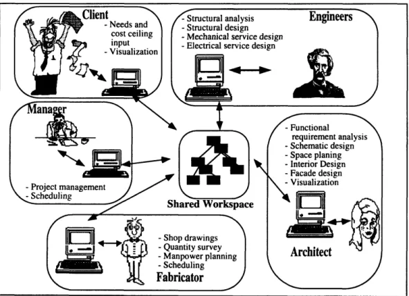
Figure 2-2 depicts a computer-based collaborative engineering develop-ment environdevelop-ment that is being developed at MIT to address the collaborative engineering paradigm. This environment called DICE (Distributed and Integrated environment for Computer-aided Engineering). DICE project has the following goals[44]:2.2 DICE Project
* Facilitating effective coordination and communication in various disciplines involved in engineering;
* Capturing the process by which individual designers make decisions, such as what information should be used, how to use it, and what it creates;
* Forecasting the impact of design decisions on various engineering fields;
* Providing an interactive interface to the designers for the detailed manufacturing process or construction planning; and
* Developing design agents to illustrate the approach.
Figure 2-2: The collaborative product development environment.
DICE project was developed as a network of collaborating design agents where the communication and the coordination of the design tasks are achieved through a global database and a control mechanism. Several domain independent shells have been built as a
2.3 COSMOS
part of the DICE initiative:: COSMOS - a knowledge base system, GNOMES - a geometric modeler, COPLAN - a constraint manager, and CONGEN - a design shell. These systems are reviewed below.
2.3 COSMOS
COSMOS is an object-oriented knowledge base system development tool. It is geared primarily for engineering applications. COSMOS integrates rule-based and object-oriented design to provide a robust framework for processing and developing procedural and heuristic knowledge [42].
COSMOS contains the following modules:
* The Object Manager module manipulates objects in-core and on disk. The module was developed using an object-oriented database EXODUS, thus providing a per-sistent storage. The module are responsible for the maintenance of all classes and instances created at run time. It also provides the information exchange facilities of rule files, classes, and instances between the user interface and the database.
* The Application Manager keeps a simple record of the information about the appli-cations in the database. It also supports a series of functions to store and retrieve this information.
* The Class Manager handles all the information exchange between the user interface and the database, regarding the C++ classes defined by knowledge base developers. * The Instance Manager takes the responsibilities of managing the instances created
by the end users. The instance manager is used mainly for setting or changing the attribute values of an instance.
* The Rule Managers manages the operations of rule files and rules in the system. They are different from the three managers discussed above. The names of the rule file and the rules are stored in the data base, but the rules themselves are stored as ordinary
---2.4 GNOMES
text files in the current working directory. The managers simply scan the working directory and get all the information through the COSMOS' parsing mechanism.
* The Parser accepts and parses the input typed in the Class Editor and Rule Editor by the knowledge engineers. As its output, the Parser generates two data structures used by the Inference Mechanism. The first data structure is an inference network that is used by the backward chaining (BC) mechanism. The second data structure is an intermediate data structure which is used by the RETE network building algorithm
of the forward chaining (FC) mechanism.
* The Inference Mechanism in COSMOS supports forward and backward chaining mechanisms in a unified framework. The forward chaining mechanism uses a modified object-oriented RETE network algorithm which has several advantages over other RETE implementations. The backward chaining mechanism is an object-oriented implementation of the KAS inference network, and incorporates a Bayesian network propagation algorithm [42].
2.4 GNOMES
GNOMES is a non-manifold geometric modeler. It is a fully functional solid modeler. It can represent and manipulate design entities at various levels of abstraction during the design evolution. A solid modeler is an important part of a CAD system which displays, manipulates, and applies various useful analyses and operations, including mass property calculations, object translations, and Boolean operations, to the design objects [21].
GNOMES was developed using the object-oriented approach paradigm. This design enables the system to be maintained and extended easily. The object-oriented design of GNOMES needed an implementation of an Object-Oriented Database (OODB) environ-ment which allows concurrent access to provide flexibility for the design group. The OODB Management System accommodates a powerful media for modeling, coordination, storage, and manipulation of engineering information [46].
2.5 COPLAN
concurrency than other traditional database architectures because of its semantic content. GNOMES exploits EXODUS OODB system capability in sharing the common data and information with other modules, such as COSMOS, and CONGEN [16].
2.5 COPLAN
COPLAN is a constraint satisfaction module which uses the Asynchronous Teams of Agents (ATeams) approach developed at Carnegie Mellon University. Murthy defines the ATeams concept [30]:
"An ATeam can be described as an organization of autonomous problem-solving agents, operating asynchronously and cyclically on shared memories."
This approach stresses on the importance of the evaluation and improvement tasks to solve a design problem. The implementation of ATeams in COPLAN also uses the object-oriented paradigm. This provides the flexibility and expandability of the module to model real-world systems. CONGEN utilizes ATeams' capability to evaluate qualitative constraints, such as the 3D relationships between objects in an application [17].
COPLAN manages the constraints generated during design generation process. These constraints can be resource restrictions, relationships between design objects, or restrictions due to the design context conditions [19].
To support the above scheme, the COPLAN constraint management includes: * A constraint representation language;
* A consistency verification scheme;
* An instantiation technique for feasible solutions; * A constraint addition handler; and
2.6 CONGEN
2.6 CONGEN
In an engineering environment, geometry plays a key role through the various stages of the product evolution. The part identification process and the fulfillment of the required functionality of each part contribute to the initial, yet critical stage of engineering design. Thus, a major portion of the designer's effort is spent on deriving the geometric structure of the objects.
Though traditional CAD systems tried to work around this obstacle, their own limi-tations restrict the designer's freedom [17]. Therefore, in order to expand the designer's capability to meet the requirements of geometric arrangements and overall system func-tionality, CONGEN was conceived as a design support system for the conceptual design process.
CONGEN integrates all the base modules in the DICE system and acts as the uppermost application layer to provide all the individual modular systems of DICE project. CONGEN can also be used to build design agents using all the modules within CONGEN framework. CONGEN synthesizes the design stages by using product block arrangement to achieve the final design. The synthesis itself depends on the integration of three problem-solving approaches: a functional decomposition, a product-oriented model, and constraint propaga-tion approaches [17]. This integrapropaga-tion will support the designer's flexibility and alternatives in generating the preliminary designs.
2.7 How to Use this Documentation
As a design support system, CONGEN incorporates the domain knowledge and geo-metric primitives needed for design. In addition, it includes an OODBMS back end. The CONGEN architecture enables its users to define their problems in the corresponding do-mains, and the usage of the knowledge base to solve the problems. Hence, there are two different kinds of users in CONGEN:
1. Knowledge Engineers (KEs). The personnel who tackles the task of providing the basic product and process knowledge and generating an application in an appropriate
2.7 How to Use this Documentation
domain.
2. End-Users (EUs). The group of people who use the application to solve specific domain problems.
Although both roles can be played by a single person or group, we need to clarify the difference in the two roles and what is expected from each group.
In using CONGEN effectively, KEs must know how to structure the knowledge for the end-user. The tasks include:
1. Developing the application.
2. Defining and developing the classes. 3. Developing the rulesets.
4. Setting up the process links which includes understanding the concepts of Goals, Plans, and Artifacts, and how they interacts with each other.
5. Setting up the relationships and geometry capability of GNOMES.
The role of the KE is very critical because the flexibility and the capability of the appli-cation depends on the knowledge defined by the KE. If the KE hardcodes the knowledge, then the end-user cannot generate expected alternatives from the application.
On the other hand, the end-users must be able to:
1. Define the problem clearly to the Knowledge Engineer to avoid future ambiguity of the
problem statement.
2. Provide the requirements and specifications of the problem. 3. Provide the constraints and relationships of the application parts.
4. Understand the basic concepts of:
* Classes and Rulesets * Goals, Plans and Artifacts
2.7 How to Use this Documentation
* Synthesizer and Geometric Modeler
5. Become well-versed in navigating CONGEN's user interface.
Within these two distinct scopes, there are two parts of CONGEN structure to be dealt with each kind of user. The Knowledge Engineers must deal with:
1. Knowledge Problem Definition, 2. Knowledge base Development, and
3. Multiple Views of Knowledge Acquisition Process. whereas the end-users must understand the importance of:
1. End-user Problem Definition, 2. Application Flow, and.
3. Notes about CONGEN implementation.
This documentation is divided into two parts: 1) Basic concepts and implementation of CONGEN; and 2) The tutorial samples. Both groups (i.e., KEs and EUs) are expected to know the basic concepts of CONGEN, and perform the tutorial samples.
The tutorials are tailored to make the user fully utilize the capabilities of CONGEN in a gradual manner. Specifically, each tutorial are organized as follows:
* Tutorial I provides an overview of CONGEN's user interface, including how to navigate through the menus, how to start CONGEN, and how to enter values. * Tutorial II presents a simple geometrical problem to the user and how to solve it
using CONGEN.
* Tutorial III presents an intermediate problem to the user, which includes multiple goals and plans. This tutorial also implements basic CONGEN application structure. * Tutorial IV elaborates on an advanced, real-world CONGEN design support
2.8 Summary
After going through the tutorials, the users can be expected to develop their own ap-plication based on the examples and concepts presented.
2.8 Summary
This chapter presented the overview of all the modules composing CONGEN. The various capabilities of the modules provide a general survey of CONGEN's capabilities as a stand-alone integrated system. The following chapter will elaborate on the important concepts employed in CONGEN.
Chapter 3
CONGEN Application Concepts
This chapter presents an overview of the capability of CONGEN in more depth. Addi-tionally, it also explains about different concepts used throughout CONGEN. The concepts span from knowledge base to product and process hierarchies. Each concept is defined and explained thoroughly in the chapter. Section 3.2, section 3.3, and section 3.4 provide the basic structures of CONGEN's application development framework. Section 3.6 provides a template of a CONGEN application for users who want to develop their own applications.
3.1 CONGEN - CONcept GENerator
As explained in the previous chapter, CONGEN consists of a layered knowledge-base system. a context mechanism manager, and a friendly user interface. Specifically, CONGEN combines together the capabilities of:
* Knowledge Representation. The CONGEN design environment integrates to-gether the knowledge-intensive nature of engineering process and the judgments made according to the knowledge. This knowledge contains the design products, the design processes, and the interrelationships between products and processes [17]. CONGEN provides the design knowledge representation scheme, maintains the design alterna-tives, and supports design as a synthesis process.
3.1 CONGEN - CONcept GENerator
Figure 3-1: The organization of this chapter.
* Visualization Support. CONGEN provides the capability of supporting form evolution and the visual interface to the designer. This is done via GNOMES, the non-manifold geometric modeler.
* Problem Solving Support. CONGEN incorporates various problem solving ap-proaches, such as top-down refinement, bottom-up reasoning, constraint propagation, etc. COSMOS, the object-oriented expert system shell, and COPLAN, a constraint satisfaction framework contribute to this capability.
* Database Support. CONGEN was built on a robust object database system provided by the University of Wisconsin, Madison (EXODUS). EXODUS provides facilities for persistency and maintenance of design data, alternatives and histories, etc.
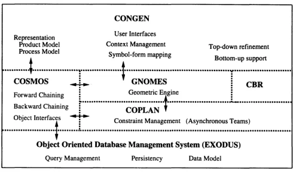
The architecture of CONGEN with all the modules is shown in figure 3-2 KNOWLEDGE AND DESIGN CONCEPTS
Chapter III
OVERVIEW OF CONGEN
IMPLEMENTATION
Visualization, Knowledge-base, etc.
PUTTING CONCEPTS TO WORK:
3.2 Knowledge and Design Concepts
Figure 3-2: The architecture of CONGEN and the supporting modules within its framework
3.2 Knowledge and Design Concepts
A definition of the design can be found in [52]:
"Design involves specifying a description of an Artifact(s) satisfying con-straints arising from a number of sources by utilizing diverse sources of knowl-edge."
Understanding the concept of design is very essential in performing engineering tasks. While engineering design essentially maps a function to a physical structure, there are many other aspects involved in the design process.
An expert usually has enough knowledge to direct the pruning of many search space branches into a single one which is most feasible and requirement-satisfying. This task becomes more complex as A relationship between the design space, the knowledge base, and the design process which departs from this analogy, is as follows:
"A design process operation such as refinement, patching, or optimization may generate a new point in design space from one or more old ones;...may
CONGEN Representation User Interfaces
Product Model Context Management Top-down refinement Process Model Symbol-form mapping
Bottom-up support
COSMOS GNOMES CBR
Forward Chaining
t...
Geometric Engine...
...
...
... 0.
a_
04.
088...
Backward Chaining COPLANObject Interfaces
Object Interfaces Constraint Management (Asynchronous Teams)
... ii
wifl ol ne l ... .... a. :... l nn ee a ... mliI lIiIes 0.. ... a ... sen ... ail ...
~lgili
mmom co0.u6....Object Oriented Database Management System (EXODUS) Query Management Persistency Data Model
3.2 Knowledge and Design Concepts
involve creating new instances of design object classes from the design knowledge base [52]".
CONGEN is a knowledge-based design tool which provides support for three design steps of:
* Identifying the design task -the user side of design.
* Configuring and instantiating the design process model - CONGEN.
* Implementing and evaluating the design process model -CONGEN Knowledge-Based Expert System.
Legend
sub-part zero or more
- mub-class directed link
Figure 3-3: The integrated CONGEN's product and process concepts.
In representing the knowledge, CONGEN utilizes COSMOS knowledge-based system. COSMOS provides the flexibility to represent the knowledge via if-then rules. Before contin-uing with CONGEN's design concepts, it is important to define some of the basic concepts of knowledge base implemented in COSMOS, they are:
3.2 Knowledge and Design Concepts
* RULESET. The set of knowledge dependent rules acts as the decision maker of a specific problem. The Rulesets depend on the knowledge engineer's capability to refine and analyze different choices at distinct levels in the design process. The Rulesets are defined as part of the COSMOS expert system shell in CONGEN. An example of a rule is as follows:
(RULE: ProblemDeadBatteryl 10 IF
(CLASS: car OBJ: $x
((problem == "unknown") AND
((initproblem == "startingsystem") AND
(headlights == "dim") ))
)
THEN (
(MODIFY
(0BJ:$x
(problem " has a dead battery")
)10000 0.001)
)
COMMENT:"If the car's problem is still unknown, but we know that there is a problem with the startingsystem and dim headlights, then we can conclude that the car has a dead battery.")
* CONSTRAINT. The Constraints in CONGEN help in narrowing down the design
search space. All artifacts are connected to constraints, such as size, time, cost, etc. The constraints restrict the values of design parameters. The constraints in the design can be categorized into [13]:
1. Synthesis. Synthesis constraints are associated with individual decision making
in the design stages. Synthesis constraints apply to decisions with a finite set of discrete choices. They are mainly within the domain of symbolic values.
2. Parametric. Parametric constraints are associated with the design parameter which represents the numerical quality of the artifact.
3. Interaction. The design of complex systems is usually decomposed into smaller design goals. Although they are separated, the subsystems may not be indepen-dent. As the subsystems interact with each other, the interaction constraints
3.3 CONGEN Product Concepts
govern the process of interaction by imposing constraints on information flow, compatibility of materials and behavior, and geometric alignment constraints.
4. Causal. The Causal constraints refer to the equilibrium equations as well as
the compatibility, constitutive, and other relationships based on the physics of the problem.
CONGEN utilizes the Asynchronous Teams of Agents constraint management module from COPLAN for solving constraint satisfaction problems.
3.3 CONGEN Product Concepts
Within the CONGEN environment, it is important to define a flexible means of en-capsulating the designer's product information and requirements. The design products are actually the mapping of functional description to concrete objects. The functional descrip-tions provide a clear requirement of the artifact's behavior and constraints. To produce the best design alternative, the functional descriptions have to be decomposed hierarchically. CONGEN's main product concept is :
* ARTIFACT. All user defined classes in CONGEN are derived automatically from
the Artifact class. An Artifact is a part of the overall design system which contains information about:
1. the functionality,
2. the form (geometry information), and 3. the behavior of the part.
An Artifact can be linked explicitly to a child Plan expanding into more subtasks in the design process. A Plan is a sequence of design decisions which will be explained in depth in the next section. In the event that an Artifact has parts that are not defined explicitly by the user in the class definition, the method make-part invoked via a rule should be used to link an Artifact to its parts.
3.4 CONGEN Process Concepts
The Artifact itself contains the information about the function, form, and behavior of the intended design. However, an Artifact does not always represent the overall design intention. A primitive Artifact may have its own functional description re-gardless of the Context in which it is created. For an assembly comprising of more than one Artifact, a design Context is needed. The design Context will involve the more complete knowledge and decisions required to integrate different Artifacts. The integration is needed in order to satisfy the functional descriptions of the overall design system. Contexts integrating the concepts of product and process will be discussed in depth in the following section.
3.4 CONGEN Process Concepts
CONGEN effects the handling of the design iteration process via the concepts of Plans, Goals, and Specifications. The process concepts provide the knowledge required of the synthesized Artifacts to be integrated as a functional entity. As a designer generates the alternatives, it is very crucial that information created within the steps can be analyzed and recorded. CONGEN's process concepts are:
* CONTEXT. This class represents the information and data generated during the design process. For example, a new Context is created whenever a new alternative is generated at a decision point. A Context contains the product information, such as the Artifacts, the design relationships, the decisions, and the design Specifications. The Contexts provide the flexibility for the designer to change from one alternative to another and analyze them for further requirement fulfillment.
* GOAL. This class illustrates the design objective, which can also be a decision point
for a design. A Goal can:
1. expand for further design Plan; 2. create a new Artifact;
3.4 CONGEN Process Concepts
4. invoke a function externally, or defined within a class.
In essence, Goals represent the functions needed in the functional hierarchy. They provide flexibility to the design to define the functions more clearly. Moreover, they enable the user to focus the attention on the abstraction of the design (Artifacts) or the refining of the design subtasks. To achieve the needed functionality, Goals may have knowledge associated with them to control the decision making process.
Moreover, the Goal can have two kinds of Rulesets associated with it - the selection or choice Rulesets and the consequence or effect Rulesets. The choice Rulesets are
built to direct the decision-making process of the choice given to the Goal, whether it is an attribute, an Artifact, or a Plan. On the other hand, the consequence Rulesets are built to modify or expand the process after the choice has been made. For example, if a designer wants to provide a set of criteria for choosing a material, the designer must first prepare the choice Rulesets. After the user makes the choice, the consequence Rulesets will be fired.
* PLAN. This class organizes the ordered sequence of Goals as part of the design
task. Basically. a Plan's role is to associate the product information (Artifacts) with the process hierarchy. A Plan can be associated with an Artifact or a Goal. In addition. a Ruleset can also be attached to a Plan. This Ruleset can change the Goal ordering according to some specific requirement. The order of the Goals inll a Plan can also be changed manually by the user in the course of the design process. * SPECIFICATION. This class contains all the Specifications necessary for a partic-ular alternative. Specifications are given by the user depending on the Context in which the Specifications are built. They are used primarily to provide user defined constraints on the Artifact relationships, the geometric representation, and the at-tributes. The Specification can be directed towards a specific instance of a class, or all the instances of a class. A new Specification instance is also created whenever a user changes an object directly through the instance editor.
3.5 Integrating the Concepts
* DECISION. This class refers to all user decisions which control the flow of the
design process. The decisions contain the design alternatives for a Goal in a specified Context. More importantly, each decision made instantiates a new design Context with a different design alternative. As multiple decisions spawn multiple Contexts, CONGEN allows the user to pursue multiple design alternatives simultaneously.
3.5 Integrating the Concepts
All the concepts laid in the previous sections contribute to the building of a design application shown in the figure 3-3.
A Context represents a specific design alternative. The Context itself consists of design tasks (Goals) referring to the particular design alternative, design flow control (Plans), user-defined Specifications, decisions made in the process, and the Artifacts created within the process. Each corresponding element in the Context is needed to satisfy the overall design functionality, such as the function, form and behavior of the design primitives as well as the decisions and the hierarchy of the design process.
The Contexts are managed through the Synthesizer. The Synthesizer allows a set of Specifications or problem-specific constraints navigate through different satisfying design alternatives or solutions. After defining all the domain knowledge, the Synthesizer also acts as the driving engine to pursue the choices based on the given knowledge.
One simple example is the process of building a box using CONGEN. Logically, the sequence of tasks of building a box is to define the constraints and Specifications, build the parts (covers), and lastly, to assemble all the parts which form a box.
This process can be synthesized as follows:
* INITIATE PROCESS
- Input constraints and initial specifications
- Create the initial assembly
3.5 Integrating the Concepts
- Create top-bottom covers
- Create east-west covers
- Create north-south covers
* ASSEMBLE PARTS
- Move top-bottom covers to the geometry placement
- Move east-west covers to the geometry placement
- Move north-south covers to the geometry placement * SHOW TO USER
The preceding steps can be mapped directly onto the CONGEN concepts with some minimal changes:
* ROOT GOAL - Create Assembly of parts
- Rulesets - Input constraints and specifications - Rulesets - Create the initial assembly
* PLAN - CREATE PARTS (has 3 Goals)
- GOAL - Create top-bottom covers
* PLAN - Create top-bottom covers (has 2 goals)
SGOAL - Create top cover
SGOAL - Create bottom cover
- GOAL - Create east-west covers
* PLAN - Create east-west covers (has 2 goals)
SGOAL - Create east cover
SGOAL - Create west cover
3.6 CONGEN Application Structure
* PLAN - Create north-south covers (has 2 goals)
SGOAL - Create north cover
* GOAL - Create south cover
* Rulesets - PLACE COVERS AND SHOW GEOMETRY
- Rulesets - Move top-bottom covers to the geometry placement - Rulesets - Move east-west covers to the geometry placement - Rulesets - Move north-south covers to the geometry placement
The preceding example is a simple exercise in structuring the knowledge and the con-straints to build a simple geometric form. In the following chapters, more examples will be provided and more features of CONGEN will be presented.
3.6 CONGEN Application Structure
As explained previously, the domain knowledge in CONGEN is represented by Plans, Goals, Artifacts, Constraints, and Functions. CONGEN was based on a formal object model SHARED defined in [56]. These elements represent the engineering design knowl-edge which involves mapping specified functions onto the physical structure of products or Artifacts. Based on the complex needs of design, a model of design product and process is thus needed to satisfy the conditions of the designer.
Modeling the design process of an application is the same as applying logical steps in performing the tasks such as those presented in the previous section. However, the CONGEN internal structure must also be understood in order to combine the subtasks with the CONGEN knowledge system.
First of all, the application must define the product and process knowledge. The product consists of the classes and the rulefiles. On the other hand, the process knowledge consists of the Specifications, the Goals, the Plans, and the Artifacts.
To form the product knowledge, the application developer must first decompose the final design system into smaller subsystems if applicable. For example, a box must be
3.6 CONGEN Application Structure
decomposed into covers, and covers can also be decomposed into inner and outer layer, and so forth. The task of breaking down the final design product proves to be very essential because the simpler the base classes, the more information can be embedded into them.
After decomposing the subclasses forming the design system, the rules must be writ-ten. However, providing the knowledge through the Ruleset is an extremely cumbersome task. The complexity of the application depends on the depth of the domain knowledge. CONGEN provides freedom from limitations in the task of providing knowledge to the process. The developer must realize that CONGEN is a conceptual design support system. CONGEN was not created to support the detailed design of an Artifact with all the sup-porting modules. CONGEN was geared mainly towards assisting the designers in the field of conceptual design.
The next step is to choose a root Goal as the top level Goal to execute the Synthesizer. The root Goal acts as the entry point into the design process. It also creates the initial Context in which all the input from the user is created. A good naming practice for the root Goal is to use the application purpose as the name of the root Goal. For example, the root Goal of a bridge design application should be build-bridge, or the root Goal of a cabin design application should be build-cabin.
The root Goal's role is usually the creation of an incomplete Artifact of the final product class with preliminary information. Even though this practice is not required, the application flow should start with a preliminary design system and finish with the final design product along with detailed information. Along with the final product class, the developer must provide another class to contain the parts created in the process.
An implementation example of the above procedure is as follows: when a box containing six covers is instantiated, all the Artifacts in the Synthesizer window are shown with links when they are attached using make.part method. If there are less than ten parts attached to a class, it is still acceptable. If there are tens, or even hundreds of Artifacts attached to a class, the Synthesizer window will be too cluttered and hard to navigate. Therefore, a container class is defined in the Cabin Design application - "Cabinpart" class acting as the container and entry point for all the parts attached to the "Cabin" class.