BEHAVIOR OF STRUCTURAL ~1ES SUBJECTED TO UNDERGROUND EXPLOSIONS
by
FUJIO V.lATSUDA
B.S., Rose Polytechnic Institute January, 1949
Submitted in Partial Fulfillment of the Requirements for the Degree of
DOCTOR OF SCIENCE
from the
Massachusetts Institute of Technology 1952
Signature of Author . .
. . . .
. .
. . .
.
. . .
.
Department of Civil and Sanitary Engineering - September 1952 Professor in Charge of Research.
.
. .
. . .
.
.
. .
.
. .
.
Chairman of DepartmentalCommittee on Graduate Students • . Head of Department • •
.
. . .
'Arch\\Ie~
ThiR matpri~1 c(lntninp inf"nn~tion affecting thf
national o<lfenr-e of the United St"ltes within tbe
nle'30in'! ot the lj~,::ri(lna1!p T..awF, Title 18. U. Ito,;, C.,
sections 7fH "nd 7!H. The t",.,,"mission ('r the
revelation I)f its contcntFl in any Inannl\t to an
BEHAVIOR OF STRUCTURAL FRAUES SUBJECTED TO UNDERGROUl'lD EXPLOSIONS
by
Fujio Hatsuda
Submitted to the Department of Civil and Sanitary
Engineering on August 22, 1952 in partial fulfillment of the
requirements for the degree of Doctor of Science in Civil
Engineering.
The object of this thesis is to establish certain approxi-mate methods for the analysis of a surface frame structure subjected to air blast and ground shock.
The analytical procedures used, graphical and step-by-step, are essentially means for the approximate integration of the
fundamental equation of motion, F = mae
The graphical methods are ideally suited for application to a one story structure ivhich may be approximated by a single
de5ree of freedom system. The step-by-step or numerical
methods may be applied to a system ''lith many degrees of freedom, although the vlOrk involved increases rapidly i'lith the increase
in the number of degrees of freedom. A means of checking the
results by the principle of conservation of energy is proposed. The structures analyzed consist of certain one story
structures tested at the Nevada Proving Ground in November
1951 and a three story structure analyzed previously by
J. Penzien and H. A. I'filliams.
Thesis Supervisor • • • • • • • Title • • • • • • • •
.
. . . .
.
.
.
• Robert J. Hansen • Associate Professor of Structural Engineering \Secretary of the Faculty
l'lassachusetts Institute of Technology Cambridge 39, l-iassachusetts
Dear Sir:
Cambridge, V~ssachusetts August 22, 1952
In partial fulfillment of the requirements for the degree of Doctor of Science in Civil Engineering from the Massachusetts Institute of Technology, I submit this thesis
entitled BEHAVIOR OF STRUCTURAL FFUU·1ES SUBJECTED TO UNDERGROUND EXPLOSIONS.
Respectfully,
ACKNOWLEDGEl.rENTS
The-author wishes to express his appreciation to the follo,\,ling individuals and organizations, without "Those as-sistance'this thesis would not have been possible.
To Doctor Charles H. Norris, Professor of Structural Engineering at ~mssachusetts Institute of Technology, for his
criticisms and suggestions during the preparation of the final manuscript;
To Doctor Robert J. Hansen, Associate Professor of
Structural Engineering at Massachusetts Institute of Technology, for his advice and direction as thesis supervisor;
To Doctor John S. Archer, Assistant Professor of
Structural Engineering, for giving freely of his valuable time in giving assistance and advice throughout the study of the problems encountered;
To my ,.,ife Amy, for typing all but the classified portion of this theSiS; and
To the Corps of Engineers, Department of the Army, and the Department of Civil and Sanitary Engineering of the
Massa-chusetts Institute of Technology for providing financial support.
To I-Iy Wife Amy
TABLE OF CONTENTS
sm-mARY
CHAPTER I INTRODUCTION •
.
.
.
.
· . . .
.
11
General
·
.
. . .
. .
·
.
.
.
.
.
.
. . ·
.
.
Previous· and Related Work
.
.
. .
.
. .
.
.
.
3CHAPTER II ELASTIC-PLASTIC RESISTANCE OF A ~m
TO DYNAMIC FORCES . . • • • • . • • • . • • General
·
.
.
.
. . .
.
.
.
. .
. . .
.
. .
.
. .
.
.
6 6 Precise Analysis • • • Approximate Analysis • • • • • • • • • • • •·
.
• • • • • • • • • • • • • • •CHAPTER III GRAPHICAL INTEGRATION OF EQUATION
OF :MOTION • • • • • • • • • • • • • • • • • General • •
· . . .
.
• •.
.
. . .
. . ·
.
• •·
.
Procedure • • • • • • • • • •· .
.
• • • • • • • • 9 29 38 • 38 · 39CHAPTER rl NUI~ICAL INTEGRATION OF EQUATION OF MOTION 56
General
· .
.
.
.
. . .
·
.
.
·
. .
. . .
• 56 Procedure.
.
.
. .
. ·
. .
.
. .
.
• • • • • • • 57 Examples • • • • • • • • • • • • • • • • • • • • • • 62CHAPTER V ENERGY CHECK . • • • • • • • • • •
·
..
.
.
• 73General • • • • • • • • • • • • • • • • • • • • • • • 73 Theoretioa1 Considerations • • • • • • • • • • • •• 73 Conclusions
·
.
.
. . .
. .
. . . .
.
. . .
.
.
.
..
.
Examples • • • • • • • • • • • • • • • •.
,
.
. • •
CHAPTER VI CONCWSIONS AND RECQl·1tclENDATIONS •
·
.
.
77 79 87
BIBLIOGRAPHY • • • • • • • • • • • • • • • • • • • • • • . 89
APPENDIX I GRAPHICAL SOLUTIONS
Introduction • • • • • • • •
.
.
.
General Considerations • • • • • •. . .
.
• •.
. ·
. .
.
.
.
.
.
· .
90 91 91TABLE OF CONTENTS (Continued)
Loauing Phenomena • • • • • • •
. . .
. .
.
. .
• • • 94Analysis . . . . . 95
Correlation with Experimental Results . • • • • • • • 96
APPENDIX II NU~~ICAL SOLUTIONS . . . • • • • • • • l23
General . . . . . 124
Calculations and Discussions • • • • • Energy Check • •
.
.
. .
. .
.
.
. .
.
. • • • • • • 125 . • . • • . • 155
sm~rn:ARY
The object of this thesis is to establish certain approxi-mate methods to obtain the response of a surface frame structure
subjected to blast loadings and ground motion.
The determination of the response of a structure to dynamic loads may be divided into three processes.
First, and probably the most approximate, is the determi-nation of the loads applied to a structure by air shock waves,
w~d, and ground motion. The treatment of these complex and
as yet not too well understood phenomena is beyond the. scope of this study~
Second, the resistance developed by the structure in undergoing elastic and plastic distortions must be determined. This can be accomplished ,'rith adequate accuracy ~ The concepts and procedures to be used are developed and illustrated in Chapter II and Appendices I and II.
Third, the equations of motion based on the applied loads and the resistance developed must be solved to obtain the response of the structure~ A simple graphical procedure for certain one degree of freedom systems and a generally applicable numerical procedure l'1hich may be used to obtain the solutions are discussed in Chapters III and IV. The graphical method is an extension of the so-called Gyrogram or Phase,-.Plane metJ::1.od. The numerical method, as far as the author knows, has not been used previously in the manner proposed.
/
of the same problems obtained by other methods, were made to investigate the accuracy of the methods of integration proposed. These checks were in general good.
The solutions obtained may also be checked by the
princi-ple of conservation of energy. Unfortunately, for structures
of more than one degree of freedom, the check yields only
negative qualitative information. The concepts involved are
discussed in Chapter V and examples are given.
On the basis of the few structures analyzed, the methods of integration proposed appear to be rapid and of adequate accuracy_
BEHAVIOR OF STRUCTURAL FRAMES SUBJECTED TO UNDERGROUND EXPLOSIONS
UNCLI\SSI·FIE[j
CHAPTER I
INTRODUCTION General
The need ~or simple and rapid methods ~or the evaluation
o~ response o~ structures subjected to various dynamic ~orces
has aluays been recognized, especially in cases '\'lhere severe
earthquakes predominate as one o~ the loading ~orces. Until
recently~ the problem has been solved by assuming a."statically
equivalentlt
load acting on an elastic structure. This method
o~ attack has proved satisfactory and is in 1-ride usage today.
It will continue, no doubt, to be an adequate method to be
used in designing a structure against such dynamic ~orces as
wind loads and earthquake ~orces. This is because these forces
are applied relatively often during the life of the structure, thus requiring that they be resisted elastically by the
structure.
Vfith the advent o~ the atomic age, ho,\"ever, structural
engineers have had to revise their concepts of the strength that should be built into their structures. This revision
has been necessitated by the follm1ing considera.tions~ The
magnitudes of the dynamic forces applied to structures by atomic explosions can be much greater than the lateral forces
customarily considered previously. Consequently, to design a
structure to behave elastically during exposure to an atomic
blast would result in prohibitive costs. On the other hand,
it appears reasonable that a structure will not be subjected
UNCLf\SSIFIED
to blast loadings of such magnitudes more than once in 1ts 11fe. Therefore, the engineers and scientists who p10neered in this field have come to the conclusion that if a structure 1s ex-pected to be subjected to an atomic blast, it is best to alloy1
it to undergo a reasonable plastic deformation; In this
manner, the additional cost of the structure is kept at a minimum ''1hile the total destruction of the structure is pre,':"
vented~
However, if this philosophy of design is adopted, the
method of II statically equivalentll loads in the usual sense
cannot be employed. This is because the amount of plastic
deformation that occurs depends upon,the response
character-istics of the structure, i~e., stiffness, mass, maximum
horizontal resistance, etc~, and the dynamic loads applied,
"
,·rhich depend on the size and point of detonation of the bomb and on the shape and location of the structure. ,There is no magic factor to be applied which "Till ensure the desired
re-sults for a given loading. Thus it is necessary :to analyze
each structure fora specific loading by one of the many methods available to the engineer; 'Of course, it is hoped that curves and tables giving the relationships between the important structural and loading parameters ,,1111 soon be
available. Indeed, information on the response of a one
degree of freedom system to certain loads is already available. l
1 Superscripts refer to references listed in the
Bibliography~
\Jl\lC.LASSlFlED
Even then, it may be necessary on occasions to check the re-sults so obtained by an independent method~ It is hoped that the methods discussed in the follmT1ng pages will prove useful "Then such occasions arise;
The emphasis in this thesis is placed on methods of analy-SiS, assuming that the loads applied to the superstructure by blast ,,,aves and to the foundation by soil pressures and ac~eler ations can be defined. In the latter case the motion of the foundation itself must be kno~m. The very complex studies of the passage of a shock wave around and through a building, the
shielding and interference by neighboring structures and
terrain features, etc., as '"Tell as the earth pressures on the foundation and the coupling of the foundation to the surround-ing soil which undergoes an intricate motion are beyond the scope of this thesis~ In the Appendices where detailed calculations are sho't'Tn, assumptions and references used to determine the loads used are discussed briefly.
Previous and Related Work
l~ny educational and research institutions have for many years been conducting intensive laboratory a~d theoretical in-vestigations concerning dynamic response of structures and
structural elements in the elastic and plastic ranges. The problem is by no means ne,\-T; hmvever, structural engineers have only recently been forced to consider the dynamic
elastic-plastiC response of their structures~ In a '!tray, the problems
UNCL,\SSIFIED'
are unique, for plastiC deformations are not considered in the usual classical solutions nor by the mechanical and aeronauti-cal engineers who also face severe dynamic problems.
The behavior of structural materials under dynamic load-ings has also been a fruitful and is still a promising field of endeavor for the research eng1neer~ In a series of
experimental programs, notably at Massachusetts Institute of Technology and California Institute of Technology, it has
<
been found.·.that the yield point of structural steel is in-creased up to
65%
under rapid rates of straining, thus in-creasing the energy absorption capacity and resistance ofsteel when loaded dynamically. Similar tests on concrete have
_ . • J
been undertaken by the National Bureau of Standards. Also, the soil mechanics division of the Department of Civil and Sanitary Engineering of 1~ssachusetts Institute of Technology is about to embark on an experimental program to determine the dynamic characteristics of soil •
.'
Information on the phenomena associated i'lith an air burst· of
a~
atomic l'TeapOn2 is quite thorough, and more datais acquired with every nuclear explosion. The problem
associated "lith the passage of a shock front around and through a structure has been studied. The problem is very complex, even for a simple rectangular structure, especially i-Then
l',indOi'1- openings exist~ For the purposes of the civil engineer,
the info~tion presented in Reference (2) is probably adequate.
Also, much qualitative information may be obtained from a stUdy
•
n\Jt"\~ r0("\F'''''IEC'
l2
! \ \,..-
L/·\~)':) ~r - [)
of the structures in Hiroshima3 and Nagasaki4 which suffered various degrees of damage due to the detonation of nuclear 'ieapons over those cities.
Information on the phenomena associated ,\-lith an under,-:-ground explosion of an atomic '\-leapon, hO,\-Tever, is relatively meager, and unfortunately is not available to the general public because of security regulations. Most of the data on underground explosions have been obtained in a series of scaled TNT shots ranging from 320 to 320,000 lbs. in various soil types. The U-shot of Operation Jangle has been the only nuclear underground explosion to date. The medium behavior has been very thoroughly measured, hO\'lever, and the results are given in several classified reports.
5,6,7
A comprehensive review and correlation of the various TNT shots and the nuclear shot is being conducted by the author's colleague, Mr. H. C. Saxe,' and will be presented as a doctoral thesis at 1,1assa-chusetts Institute of Technology.Some model and full scale tests on structures have been conducted by certain U. S. Government agencies at the Pacific and Nevada Proving Grounds, and at Dug"lay, Utah. A large portion of this thesis deals with the analyses of certain
structures in the Army Structures Program which "Tere tested in
November, 1951 at the Nevada Proving Ground.
CHAPTER II
ELASTIC-PLASTIC RESISTANCE OF A FRAME TO DYNAMIC FORCES
General
In this chapter the method of determining the elastic and plastic resistance developed by the columns in a frame to resist lateral dynamic forces ''1ill be discussed~ A precise analysis based on the distortions of the frame and approximations using idealized mass- spring systems "rill be treated. The basic
assumptions used in the analyses are:
1. The forces on the superstructure are concentrated at the floor levels.
2; The masses are concentrated at the floor levels~
3;
Dead load stresses are neglected.4;
Vertical dynamic loads are neglected. 5~ Damping is neglected~6. The foundation remains stationary ,·rhen forces are applied to the superstructure alone.
7.
A column behaves elastically until its full plastic moment is developed at one or both ends; it then be-haves as a column hinged at one or both ends 'tiith the full plastic moment acting until an elastic condition is again obtained;8; With the resumption of elastic action the appropriate hinge is removed;
Consider the frame shown in Figure 1. Due to the dynamic forces PI' P2' and P3, a lateral displacement of the frame ''1ill
result. The applied loads are resisted by shears developed
in the columns due to the distortion of the frame. The alge-braic sum of the applied force P and the shears acting on a
mass constitutes the unbalanced force which produces ~n accele!7 ation of the mass.
P
3
D Hm3
P2 C Gm
2 PI .F A E Figure IThe follm-ring sign convention will be adopted and used throughout this paper.
l~ The driving forces (p) are positive when acting to the right~
2;
The absolute deflections, velocities, and accelerations, x,x,
andx,
respectively, are positive to the right.3.
The relative deflections, velocities, and accelerations, y,y,
andy,
respectively, are positive to the right.4~ The moments acting on the ends of columns are positive when acting clocIDi1se.
5; Joint rotations are positive ,-rhen cloclaiise. 6. Chord. rotations are positive uhen clockwise;'
7;' Shears acting on the ends of a column are positive
' " " ,
counterclocln11se, i. e., positive shears are associated with positive moments.
8~ Inertia forces are positive to the left, i.e., a posi-tive acceleration produces a posiposi-tive inertia force; The resistance developed at any mass against the applied load at that mass will be defined as the algebraic sum of the .shears beloi'1 and above the mass in question~ The resistance
will be taken positive to the left~ Therefore, with positive shears acting,
(1)
"There,
Rn
=
Resistance developed at then~
mass.Vn+l
=
Total shear in the columns above then1h
mass. Vn=
Total shear in the columns below the n~ mass.Figure 2
Applying dlAlmbertls prinCiple, the summation of forces acting on the nth mass \"lill give the differential equation of motion,
(2)
''There,
Pn
=
Driving force applied at the nt~ mass,~Xn
=
Inertia force at then~~
mass,~
=
nth mass, andXn
=
Absolute acceleration of the nih mass.For a structure \'1ith n mass pOints, there will be n such differential equations of motion. A simultaneous solution of this set of equations will yield the response of the structure to the dynamic applied forces; Before these equations can be integrated, however, the resistances must be expressed as
functions of the dependent variables xn' the absolute displace.":. ments of the n masses; Only the determination of these
re-sistance functions will be discussed in this chapter~ The methods for the approximate integration of the equations of motion are discussed in Chapters III and IV~ In the following discussions, it \,Till be assumed that the deflections xn are known at any time.
For the purposes of discussion a three story structure subjected to dynamic forces acting on the superstructure ,\'1ill be considered. The method is perfectly general, hOliever, and may be extended to structures of any number of stories or to forces developed by support vibration; (See, for example,
Appendix II, Three Story Structure Subjected to Support Vibration, Precise Resistance Functions.)
Precise Analysis Determination of Resistance Functions
The methods to be used in determining the precise resistance
functions ,.,ill nO,"T be developed~ The discussion ,\,lill include
the determination of the resistances in the elastic and plastic ranges, as well as the criteria for the initiation of plastic action and the resumption of elastic action.
As stated previously, it is desired to obtain the resistance developed at a mass as a function of the displacements of all the masses; To attain this end, the structure is analyzed by the moment distribution method for the three cases of distortion illustrated in Figure 3. Nota that l.,e are dealing here ""ith static distortions and forces.
Xl
=
1 in. x2=
0 ~=
0 (a.) Xl=
0 x2=
1 in. X3= ()
(b) Figure 3 Xl=
0 x2=
0 x3=
1 in. . (c)From the solutions obtained for the distortions indicated
in Figure 3, the following equations are obtained. These and other_ equations similar to them 1'lill be called influence
equations, since theyshol'l the influence of the deflections on the quantities involved.
MAE
=
l-1AB xl + MAB x2 + I~ X31 2 . 3
l-~
=
J.t1:sA xl +M.sA
x2 + I~A X31 2 3
l'13C
=
l~C xl + ~C x2 + ~C x31 2 3 etc.
The notations are defined below.
(3)
MAE
=
Total bending moment at the A end of themember AE due to the distortion of the entire frame. (See Figure
1)
1-1:AE
=
Bending moment at the A end of the member AB Idue to a unit deflection of the first story. (See Figures 1 and 3-a)
MAE
=
Bending moment at the A end of the member AB 2due to a unit deflection of the second story~ (See Figures 1 and 3;b)
MAE
=
Bending moment at the A end of the column AE 3due to a unit deflection of the third story. (See Figures 1 and 3~c)
Xl
=
Absolute deflection of the first story.X2
=
Absolute deflection of the second story. x3=
Absolute deflection of the third story. The other terms are defined in a similar fashion.Equations (3) state that the total moment acting on the ends of a column for a given distortion of the frame is ob-tained by the superposition of the moments produced by the displacement of each sto~ separately. Also, for a given
moment at one end of a column, there is an infinite number of combinations of xl' x2' and X3 '\'1hich ,\,1ill produce that moment. This means that the deflection of a given story at w'hich a plastic hinge is formed in a column in that story cannot be predetermined, since the moments in any column depend upon the displacements of the other stories as well as its own story.
From equations (3) the shears acting on the ends of a column may be calculated~ Since the external loads are concen-trated at the floor levels, the shear developed in any column is given by
where,
(4)
v~
=
Shear in a column in then1h
story,MT
=
Bending moment at the top of that column,l~
=
Bending moment at the bottom of that column, and~
=
Height of the column in the nt~ story~h
1
n ,'-'~ Figure 412
VI nThen,
v
n=
"V'
L n (5)where Vn is the total shear in the niB story,-and the summation includes all of the columns in that story ~
Therefore, a set of influence equations for the story shear may be \vritten. w'here, VI
=
aixl + a2
x 2 + a3
x3 V2=
biXl + b2
X2 + b3
X3 ai ~ IHll hI b' -1 - Z).vI2l ~. c1 -r -'L
r'
i:2l h3' at -2- 21-112 hI etc~ (6)The notation H2l, for example, indicates the moment at one end of a column in the second story due to a Ul~it deflection of the first story, and the summation includes the top and bottom
moments of all the columns in that story.
Finally, the influence equations for resistance are obtained from equations (1) and
(6).
where, ~
=
alxl + a 2x2 + a 3x3 R2=
blxl + b2x2 + b3~ a l=
(b t - at) 1 (;.1 1 a2=
(b 2. 1 _ a2)
a3=
(bS -3 a ') 3 bl ==(c
1 r _ b 1 1) cl=
I -cl etc.(7)
The steps outlined above are merely the usual steps in-volved in calculating the holding forces, i.e., the forces applied to distort the frame into the position assumed, for the conditions of distortion indicated in Figure 3~ Note tllat the resistance functions indicated in equations
(7)
are equal in magnitude to the respective holding forces, with, helieVer, opposite signs~ That is, the resistance developed is equal and opposite to the load applied~ This must be so in the static case, of course. In the dynamic case, the resistances may be thought of as the forces mobilized due to the distortion of the frame to counteract portions of the dynamically applied loads~ The unbalanced portions of the applied loads causethe masses to accelerate. At the later stages of the distortion, the resisting forces will be larger than the applied loads, and
---...
_---negative accelerations ,.,ill result.
Note that equations
(3); (6),
and (7) assume that the response is elastic and the magnitudes of the moments, shears, and resistances increase without limit as the deflectionsin-crease. Actually, however, the moments, and hence the shears and resistances are limited by their ultimate values. Since the ultimate moments for the columns depend upon the physical characteristics of the respective columns and the rate of loading, they can be predetermined~ Thus, knOrTing these ultimate values, equations
(3)
may be utilized for any con-figuration of the frame to determine whether or not thelimit-ing value of the moment in any column has been exceeded~ When the ultimate moment is exceeded in any column, a
plastic hinge is formed and the structure has to be re:analyzed ,\'lith hinges inserted in appropriate locations. A new set of
influence equations is thus obtained i'lhich define the re-sistances. For example, suppose that hinges form at the bottom of the first story columns simultaneously~ Then the
structure to be analyzed is as shol'm in Figure 5~
P3---'~--- P2--~+---~ PI--~+---~
Figure 5
The inrluenoe equations are obtained by the superposition or the moment ·distribution solutions indioated in Figure
6.
Figure 6
Note that in Figure 6, in addition to the three sidesway
so-lutions, an additional solution ror the oase or zero derlections with the ultimate moments actin6 on the hinges is required'~
This solution adds a constant term in the equations correspon~ ing to equations
(3),
(6), and(7),
but introduces no compli-cations; The procedure in evaluating these equations ,is', the same as in the elastio case and will not be repeated here~When the next set or hinges are formed, hinges are again inserted in appropriate locations and another set· of influence equations are obta1ned~ This procedure is repeated until the response returns from plastic to elastio when the hinges are successively removed. The criterion for the resumption of elastio action will be disoussed in later paragraphs;
It is less tedious and the errors involved are usually small, if instead of accounting for eaoh hinge as it forms, it is assumed that plastic hinges are formed Simultaneously at the tops and bottoms of all tEe"columns in a given story. This
may be accomplished by allowing the shears in equations (5)
to increase until the respective ultimate story shears, Vu ' are reached, where
,
(8)where the subscripts u denote ultimate values, and the summation includes all the columns in the story under consideration. The other symbols were defined previously. ~he ultimate story shears calculated by equation (8) may then be used to establish the
change from elastic to plastic action instead of the ultimate moments in the columns.
This approximation was used in all of the analyses made. For example, see Appendix II, Three Story Structure Subjected to-Air Blast, Precise Resistance Functions~
In the actual calculations involved, it will be found more convenient to use relative deflections and accelerations, y and
y,
instead of the absolute values. The quantities are defined belO'\'1.Y -2 - x - x 2 "'- 1
:17
In terms of these relative values, the e~ations of motion take the form
Pl';' ml (Yl) ,~
I1.
=
0P2 .":" m2(Y2 + Yl) - R2
=
0P3 .-::: m3 (Y 3 +
Y
2 +Y
l) ;-: ~ = 0 •The resistances which were previously expressed as functions of the absolute displacements must nOli be expressed as functions of the relative displacements defined above; This may be done by manipulation of the numerical constants appearing in
equations (7).
For example, if w'e wish to express Rl in terms of the relative deflections, given
we write Therefore, Rl
=
alxl + a2x2 + a3~ , Rl=
ty 1 + uy 2 + vy 3=
t(Xl) + u(x2 - Xl) + V(X3 al=
t ':'" U a 2=
u ,- v a 3=
v , and the desired form isRr
=
(al + a 2 + a 3),Yl + (a2 + a 3)y 2 + a 3Y3 ;The shears and moments may be expressed in terms of the re,':'" lative deflections in a similar manner. Thus the influence
equations for the moments, shears, and resistances may be \'rritten as follo,\'1s:
etc.
Vl
=
(ai)rYl + (a2
)rY2 + (a3
)rY3 V2=
(bi)rYl + (b~)rY2 + (b3
)rY3 V 3=
(ci) rY 1 + (c2
)rY2 + (c3
)rY3 Rl=
(al)rYl + (a2)rY2 + (a3)rY3R2
=
(bl)rYl + (b2)rY2 + (b3)rY3 ~= ( .cl )rY
1 + (c2) rY 2 + (c3)rY3. .
( 12)
(13)
where the subscripts r mean that the values of the constant coefficients are the ones obtained as outlined above for the relative deflections which replace the absolute deflections.
Transitions from Elastic to Plastic and Plastic to Elastic Action The behavior of a rigid joint in the transition from elastic to plastic and from plastic back to elastic action will no,.; be
studied. Consider the three story frame in Figure 1 responding elastically to the dynamic forces P.
The original right angles of the members meeting at a joint will be maintained until the plastic moment is exceeded in one of the members~ Suppose at t
=
t l, the first story is plastic and hinges are just formed at both ends of membersCB and GF (FigUre 1) while the top story is still elastic. Joint C will be considered ~or the rollowing discussion.
Figure 7
Due to the continued de~ormation of the ~rame in the same direction, the members CD and CG will rotate ~urther while maintaining their original right angle con~iguration. The member CB, however, rotates independently of the other two so that a short interval o~ time later at t
=
t2 the configuration is as shovm in Figure 7-b. The additional rotationAe
o~members CD andCG depends -only on the increment of relative deflection of the third story, and is independent of the second
story deflection. The increment of rotation Ae~ of member CB on the other hand, is proportional to the increment o~ the re-lative second story de~lection and is independent of the elastic rotation o~ members CD and CG.
Note that the hinge in member CB is a one-liay hinge, similar to a ratchet of a socket rTrench, ~or example. A re-lative rotation is allowed only as long as that rere-lative ro-tation is increaslng~ I~ at any time the relative rotation tends to decrease the hinge is locked and elastic action ensues
until plastic moments. are again reached; These relative rotations may be calculated in the following manner.
The frame is analyzed 'VTith hinges inserted in appropri-ate locations as indicappropri-ated in Figures 8-a and 8-b.
(b)
F1gure·8
Note that these solutions are necessary anyway to obtain the influence equations for reSistance; The equation for the moments in member CG in terms of the deflections will have the form
where
MeG
=
d + e(x3 ; x2)MGC
=
f + g(x3 ~ x2 ) ,d
=
moment at the C end of member CG due to the(14)
ultimate moments of the second story columns applied at C and G as sho'VID in Figure 8-a, f
=
moment at the G end of member CG correspondingto d,
e
=
moment at the C end of member CG due to a unit deflection of the top story as shown in Figure 8-b, andg
=
moment at the G end of member CG corresponding to e~The change in these moments during any time increment At after the formation of the hinges is then,
~MOG
=
eA (x3 - x 2 )(15) The increment of rotation at each joint is then readily calcu-lated by applying the moments in equations (15) to a conjugate beam representing the girder CG and illustrated in Figure
9.
Note that the conjugate beam uses the so~called beam sign
convention which is different from the sign convention adopted in this thesis. ,I:lMCG EI Figure
9
flM_ ' ....:.1tQ EIIn a bent more than one bay deep, or in an unsymmetrical bent one bay deep, these incrementa.l rotations in genera.l "rill not be the same for all joints. If each hinge is being
accounted for individually, ~o difficulties are encountered. If, hOi-rever, it 1s assumed that all the hinges in a given . story form simultaneously, an average value of the .rotation
must be used; Then the equation for the average incremental
rotation 1'lill have the form
69
=
(e + g)~(x - x2).
av 2 3
(16)
The incremental rotation 6ft' of member CB is a rigid body rotation and is simply
where
~,,' _ 6Ypl
~ - h
,
(17)
AYpl
=
increment of deflection during \,lhich the columns are plastic, andh
=
length of column.If the assumption of simultaneous formation of hinges is made, in determining whether or not elastic action is resumed, the average plastic rotations of the tops and bottoms of the columns must be considered~ In the example being considered, the top story is elastic and the first story is plastiC, while the second story is changing from plastic to elastic~ Then the increment of plastic rotation is given by A9' ~A9av for the top hinge and b9' for the bottom hinge. The average of these two quantities must attain a sign oPPosite to the pre-vious total plastic rotation before elastic action can be assumed.
If the first as \'lell as the third story are elastic while the second is changing from plastic to elastic, the
same considerations are 1nvolved~ HOi'leVer, the increment of plastic rotation of the bottom hinge 1iill be given by A9 1- b9~v'
1'There 691
av is the average increment of rotation of the elastic members such as BA and FE (Figure 1). See Appendix II, Three
Story Structure Subjected to Support Vibration, Precise Resistance Functions for numerical examples.
The reversal of the increment of relative deflection of a story v1hich is plastic may be usually used as a good ap-proximate criterion for the resumption of elastic action.
A brief summary of the discussion to this point may be helpful before we proceed further~
By means of the influence equations which define the resistances as functions of displacements '\'1e are able to calculate the response of a structure to dynamic loads~ The actual method of integrating the equations of motion i'1ill be discussed in the next chapter;
By accounting for the shears, the time of formation of plastic hinges can be determined~ When plastic action is obtained, '\re proceed with the integration using a nei'1 set of influence equations. The process is repeated as new hinges form~
Plastic action is assured as long as the plastic ro-tation at the hinge is increasing numerioally~ When the opposite case is obtained, elastic action is resumed; The analogy to a ratchet is useful in visualizing the action.
With the return to elastic action, of course, the appro,:", priate hinges are removed and the corresponding influence equations are employed. The process is repeated until all hinges are removed or- until the analYSis is stopped; HOirever, certain complications are encountered in the analysis when elastic action is resumed and v;ill be discussed in the
ins paragraphs.
Specifically, the problem is to determine what artificial displacement of the story that is returning to elastic action is to be used in calculating the resistances~ Obviously, the actual. deflection at which elastic action is resumed, and
subsequent deflections of that story, cannot be used, for such a procedure would imply that all of the prior displacements had been elastic~ Therefore, a ne'i'1 datum must be established from 'i"1hich the artificial displacements are measured. An
analogous situation is encountered in the case of a spring having the characteristics sho'iin in Figure 10. As long as y
is less than I::. , the limiting elastic deflection, the resisting
force is proportional to y, i~e., the resistance is elastic~ "Then y exceeds /)., the resistance becomes constant and
in-dependent of y, i~e., the resistance is plastic, as long as y keeps increasing; If at any time y begins to decrease, the resistance begins to decrease along the same slope as in the elastic case.
R
y
Figure 10
If the resistance is to be expressed as a function of y in all three stages, lt must be wrltten as
R
=
ky (y ~Ll) (18)(y~Ll), (y>o)
(19)
(20)
where,
k
=
spring constanty pI
=
plastic deflection ,\"hich is not recoverable_ Thus it is seen that in the thlrd stage, if the artificial displacement (y - Ypl) is used in the resistance equations by shifting the R axls to the rlght by the amount Ypl' the behavior of the system can be described~In the case of a frame the procedure is as follows_ As mentloned previously, using relative deflections has certain advantages, 'so the discussion ''Tl11 be in terms of y _ Suppose that at t
=
tl the first story is just plastic while the other two stories remain elastic throughout the following discussion. Let the values of the first, second and third stor,1 relative deflections at t=
tl be Yl' Y2' and Y3' respectively~ Some
time later at t
=
t2, the first story returns to the elastic state, the deflection at that time being denoted by Yl- Let the relative deflections of the other t"10 stories. be Y~ and' Y
3
at t=
t 2- Since all three stories are again elastic, the resistance equations for the elastic state should be appllcable~However, since Yi includes some plastic deformation, it cannot be used as such in the resistance equations~ Note that Y2 and Y3 must not be adjusted, since no plastic deformations are
involved in them •.
(a)
Figure 11
y , :3
One may be tempted to use (Yi - Yl) a.s the plastic de,,:", flection and use it to establish the new datum for the first story relative deflection. If this is done, referred to the new datum, the deflections at t
=
t2 would be Yl' Y2' and Y3. This procedure is incorrect, hO\'lever, for the follm.,ing reason. Suppose that at t=
tl the configuration of the frame is as shown in Figure ll~a, and at t=
t2 as shovm in Figure ll~b.Examination of the shear equations in terms of the relative deflections show that if VI had reached ·its ultimate value for the values Yl' Y2' and Y3 at t
=
t l , it will not, ingeneral, have its ultimate value if Yl' Y
2'
and Y3 are sub-stituted at t=
t? In other words, "19 must select theeffective value of the first story relative deflection (Yl)eff so that when used in the equations for shear with Y2 and Y3 at t
=
t 2, the first story shear will equal its ultimate value.Note that in the shear equations V2, V
3, and (Yl),eff are knm·m, while Vl is equal to its ultimate value and all other quantities are known. In the integration process described later, the
story shears do not appear as such; therefore, there is some advantage in using the resistances which do appear to' find
(Yl) eff~ From equations (13), "
Rl
=
(al)r(Yl)eff + (a2) r(Y~P + (a3) r(Y:V(al)r(Yl)eff +
~
R2
=
(bl)r(Yl)eff + (b2)r(Y2) + (b3)r(Y3)-
(bl)r(Yl)eff + ~~
=
{cl)r{Yl)eff + (c 2)r(Y2) + (c3)r{Y3)=
(cl)r(Yl)eff + ~where, the-terms containing Y2 and Y3 are replaced by the constants Q,.
( 21)
From equation (1) the shears may be 't'lritten as follows.
V
l=
,-(Rl + R2 + ~)=
-Cal + b l + cl)r(Yl)eff,- (~ + ~ + ~)(22) V2
=
,-(R2 + R3)=
-(bl + cl)r(Yl)eff'-:: (~ +%)
V3=
-R3=
-{Cl)r(Yl)eff- ~Thus, using the ultimate value of Vl , (Yl)eff is calculated,
and !mouing (Yl) eff' V 2 and V3 may be calculated.
The effective relative deflection for the first story
just calculated and subsequent relative first story deflections are artificial, and are used only to calculate the resistance
offered by the columns in the first story~ The actual re~
lative deflections of the first story are obtained by adding to this effective value the difference between the deflection at which elastic act10n 1s resumed and the deflect10n fOUl~d
above, i.e., by adding (yi)- (YI)eff. The detailed analysis illustrating the steps outlined above is presented in Append1x II, Three Story Structure Subjected to Support Vibration,
Precise Resistance Functions.
Approximate AnalYSis General
The prec1se analysis discussed in the preceding section may become too' laborious when many stories are involved~ . Hence
reasonable approximations must be considered. Such approxi-mations are discussed in the follo''l1ng section~
In the elastic range the influence equations developed earlier will contain as many terms as there are degrees of freedom. For a fifteen story rectangular frame, for eY~mple, the resistance at any floor will be a linear combination of the fifteen floor deflections~ Obviously the labor involved
in evaluating the resistance at each floor will be unreason~ ably great; In such cases a modified set of influence equations may be used by neglecting the influences of floors more than
say twice removed from the floor in question~ The modifications are quite flexible and will depend upon the accuracy desired and the characteristics of the structure. The labor involved will still be great, hOl'lever, especially when transition zones
from elastic to plastic and plastic to elastic actions are approached;
A second possibility is to assume that the building may be represented by a series of masses and springs as shown in Figure 12, each of the springs having the characteristics shol'm in Figure 10. It is assumed that the shear in a given story is dependent only on the relative deflection of that story and is independent of the action of the other stories.
P 3 m3 k3 P2 m2 k2 PI ml kl Figure 12
Note that in this method the deflection at which the elastic range is exceeded is predeter.m1ned~ Much of the work is
eliminated when this is so, s1nce as the integration progresses, the change from elastic to plastiC action becomes obvious by the deflection exceeding the limit1ng elastic deflection. Also, when, a deflection decreases at any time during plastic action, elastic action is assumed to have resumed, thus
e~iminating the necessity of checking the increments of ro-tation; The effective displacement for the resistance will be merely the actual deflection minus the plastic deflection;
Under this assumption, the response of the structure will be a function of the applied loads, masses, ultimate shears, and the spring constants. For a given problem, the first three are known, while a certain amount of freedom exists in the
selection of the last; Two of the more convenient selections will be discussed here. The detailed analyses based on these assumptions are presented in Appendix II.
Method A, Approximate
The first method is to assume that the girders are
in-finitely rigid; If the columns are fully fixed against rotation at the top and bottom, the shear-deflection curve in the elastic region, neglecting axial loads, is given by
RIG
Y
=
l2EI • (23)Similarly for a column with one end pinned and the other fixed against rotation, the:··cot'responding equation is
Rls
y
=
3EI •(24)
As before, the ultimate shear is given by equation (8); hence, the limiting elastic deflection may be calculated. The
influence equation for the resistance at any interior mass will then consist of t"10 terms only, i. e. ,
where Yn and yn+l are the relative deflections belm'! and above the mass in question and
1SJ.
and l~+l are the stiffnesses of the columns belol" and above the mass. The resistance for the top mass ,\,lill depend only on the top story relative deflection.'{hen plastic action is reached in any story, as determined by the deflection, the shear in that story becomes constant and equal to the ultimate value~ When a transition from plastic to elastic action occurs; the effective displacement to be used in calculating the resistanc~ is obtained by subtracting the plastic displacement from the actual displacement.
Hethod B, Approximate
A slightly better approximation is obtained by the follmT-ing procedure. In general, when the frame is in its maximum deflected shape, the absolute deflection of a story becomes progressively larger as the stories go from the IO,\,Test to the highest. Under these circumstances, the springs representing the columns should be softer than the springs used in Method A~
Thus, some __ attempt is made in this method to reduce the spring constant by taking into account the joint rotations while
assuming still that the shear in any story is a function of the relative displacement of that story alone~ The method is out-lined below~
A moment distribution solution is obtained for each of the three cases of sidesylay shmm in Figure 13. For a unit
re-lative deflection of a given story, the moments due to the assumed chord rotations are distributed and the shear in that
story is found by equations
(4)
and(5).
The value of the story shear found in this manner together ''lith the assumed relative deflection give a point which defines the slope of the elastic portion on-the shea~deflection curve~,Xl
=
1 in. xl ~ 0 Xl=
0x2
=
1 in. x2=
1 in. x2=
0x3
=
1 in. X3=
1 in. x3=
1 in. Figure 13The ultimate shear in the story is calculated as before and the shear is al101"led to increase "lith increasing relative deflection to that ultimate value along the slope found above. For any deflection larger than the value at ''lhich the ultimate
shear is reached, the shear is assumed to be constant, provided that the change of deflection is positive~ \ihen the deflection begins to decrease, the shear decreases along the slope
es-tablished previously; The shea~deflection curves for each story are now defined a.nd are used as outlined in Hethod A.
v
U /---;.-+---,~---~~---~-y n.
Figure 14
Comparison of Results
A three story structure subjected to air blast ,·ras analyzed using the resistance functions obtained from the precise analysis and the approximate methods, Method A and lolethod B~ The
pro-cedure used in integrating the simultaneous equations of motion using these resistance fUnctions is discussed in Chapter IV, and the detailed calculations are included in Appendix II. The
results from these analyses are shown in Figures 15, 16, and 17, which shm·r the transient relative deflection curves for the first second, and third story masses, respectively; Note that the calculated deflections may be seriously in error for the higher stories when the approximations for the resistance are made, assuming of course, that the analysis based on the precise resistance fUnctions is accurate. It '\'rill be shm·m later that this is so.
CHAPTER III
GRAPHICAL INTEGRATION OF EQUATION OF MOTION
General
The folloi'1ing graphical procedure is ideally suited for the analysis of a single degree of freedom system without damping, subjected to vibratory motion of its support or to dynamiC forces applied to its mass. The two conditions of loading on the system are indicated in Figure l8~ All quanti~
ties are positive as shol-Tn, and are defined belol'l.
~-x
.
x _ x~ p (a) (b) Figure 18 m=
mass k=
spring constant xo=
displacement of support Xo=
velocity of support Xo=
acceleration of support x=
displacement of massx
=
velocity of massx
=
acceleration of mass.
y~y-y
=
relative displacement between massand support
=
(x - Xo).
y
=
relative velocity between mass and support=
(x - x )
o
..
y
=
relative acceleration between mass and support=
(x - Xo)P
=
dynamic force applied to massThe method is applicable ",hen the resistance of the system is given by anyone of the curves sho"m in Figure 19. HOi-lever, when the resistance-deflection curve is as indicated in Figure
19~d and under certain conditions as in Figure 19-c, a con-venient graphical method has not been found for the response beyond y
=6,
and semi-graphical procedures must be used. For the solutions presented in Appendix I, the resistance curves were assumed to be represented by Figure 19-:-c.In order to apply the graphical procedure, the forcing functions must be idealized into rectangular blocks. For example,
x
and P are approximated as shown in Figure 20 byo
letting each block replace an equal area of the actual curve for the corresponding length of time At~ The selection "of 6 t is arbitrary, depending on the accuracy desired.
Procedure Elastic Resistance
In order to establish the procedure, consider first the case of support vibration with elastic response resulting.
(Figures lS-a and 19-a). The equation of motion is:
(26)
R R --~----~~---~ y ---~~~----~y (a) (b) R R b ---~~~~--~y y (0) (d) Figure 19 ~---+--~~t Figure 20
40
In terms of the relative displacement and acceleration, equation (26) is written
.. k ..
Y + - y = - x m -, o· (27)
If Xo is assumed to consist of a rectangular block of duration At, the solution during that interval ~t ta}~es the form
Xo
y
=
01 sin mt + 02 cos rot - ~ , (28)where mS is defined as
! .
If the initial conditions are such that at t
=
0, Y=
Yo and. .
y
=
Yo ' the constants may be evaluated to give.
. . .
.
Yo x x
. y
=
ill.
sin O)t + (Yo + ~)cos rot ,-# .
(29)Equation (29) may be ,\,Tritten more conveniently
..
. . .
(y +~)2
+(*)2
= (
Yo +~?2
+(~)2
=
1'2 ,
(30) or where.
~=
r cos(mt +C:P),
..
.
r=
( Yo + ~XO)2
+(YO)2
(J)x
y + 0 cp=
arctan o. (i)Jf Yo m·Both equation (30) and equations (31-a) and (3l-b) shm., that
,
.
the solution of the problem is a circular arc in the •• (~, m y)
• x
plane with center at ~
=
0, y= -
~ ~ The angle subtending0) m
the circular arc is given by wot, \·z"here.6.t is the interval over which the forcing function Xo is constant.
Note that all quantities except wand t appearing in the above equations and subsequent equations have sense ( plus or minus) as '\'rell as magnitude associated ''lith them. Hence when arithmetic manipulations are required, care must be taken to use the proper signs. The sign convention is defined by
Figure l8~ The graphical construction automatically gives the proper signs to the quantities~
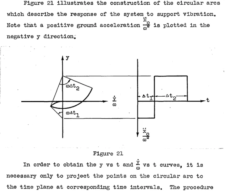
Figure 21 illustrates the construction of the circular arcs which describe the response of the system to support vibration.
x
Note that a positive ground acceleration
wi
is plotted in the negative y direction~ y.
:L c.o Figure 21 ... -~t2 I--...--...;;;;..----...-t
.
In order to obtain the y vs t and ~ vs t curves, it is neoessary only to project the points on the circular arc to the time plane at corresponding time intervals. The procedure
is indicated in Figure 22~ y
.
:L 0) Figure 22.
:L y, 0)Consider now the case of a dynamic load applied to the mass with elastic response resulting. See Figures 18-b and
19-:-.a~ The differential equation of motion is given by
mY+ky=P. (32)
With the initial conditions as before, the solution may be written or where
.
P 2 (YO) 2 2 (y - -) + r - 0 k 0) - , P y - k=
r sin (rot +.,,).
:L=
r cos(rot + <p) , ro.
r=
(Yo - P Ie) 2 + (ol) Yo 2. P -1 ... ( y....;o~---=k~)
l'
=
tan - . Yoro-43
• (33) (34-a) (34-b)Note that equations (33), (34-a), and (34-b) are identical in for.m with equations (30), (3l-a), and (3l-b), respectively, with
+
~
replaced by -~.
Hence, the graphical procedure will be identical in the t",o cases, except that a positive load applied to the mass i-Till be plotted in the positive y direction~ Note that the effect of ground shock and air blast can be supe~ imposed as indicated in equation (35).Xo
p 2 . 2Xo
P
2(YO)2
(y + ~ ,- k). + ( ; ) = (Yo + (D2' .":" k) + (I)
Since the procedure is the same for either type of load-ing, hereafter only the complications arising from the various resistances will be considered. For the purposes of
dis-cussion, vibratory motion of the support "rill be assumed to supply the loading;
Semi-Plastic Resistance
Consider no\-, the resistance curve shOim in Figure 19-b. Until y
=
~ equation (27) w'ill apply. Beyond y = 6, theequation of motion is
.• kl [. (k ,- kl )
AJ
Y + -m Y
= .-.
... x 0 + -. m - u (36) "There kl is the spring constant in the semi-plastic range.This equation is identical in form \'lith equation (27), and with the initial conditions y
=
Yo andy
=
Yo at t=
0, the solution may be written as follo'\'IS:Y - t:J. + ~2 (-:::'2' + I:l ) + ( :L )
~
(1)2Xo
~
2 • 2(I) 1 (I) (I) 1
where
Equation
(37)
again represents a circle, however, in the• . 2 i .
(x:,
y) plane with center at y=
b - ~ (~+6), :L=
O.WI . fil ill fil
Thus, in the graphical solution a change of scale is involved when the response passes from the elastic to the semi-plastic
stage (y>6). The construction is indicated in Figure 23.
t
-... -Figure 23
''fhen a velocity reversal occurs, (point b in Figure 19-b) , the stiffness to be used is the same as in the elastic case, and circular arcs with the original scale are again drawn. In this region the resistance may be represented by
R= k(y - YpI).' and the differential equation of motion is
.. k k ..
Y +
iii
Y=
iii
Y pI - Xo •The 'solut~ontakes the form .
45
(38)
Therefore, using a new variable y 1
=
Y -:- Y pI' Y ~ == Yo - y pI ' equation (40) is \'lritten..
. . .
(yl
+~)~
+(*)~
==(Y~
+~)2
+(~~)2
•
- -(4{) )(41)
(42) Equation (42) is identical vlith equation (30) and therefore the construction is identical; Graphically the change of variable is accomplished by starting the circular arc in theelastic range at y == t:::. as shO't'Tn in Figure 24~
y
..
Figure 24.
:L ())If the change of variable is not made, the circular arc
labeled@ \'lill be tangent to
<D,
but the enter of the circleand the lines marked 6 will have to be moved accordingly ~
Plastic Resistance
Consider next the resistance shQ'i'ffi in Figure 19-c. In the plastic range (y
>
A), the equation of motion is- Let
-.' + k A
Y m
=
-•
Then, integrating equation (43), '\-re obtain
a.t
2y
= -
~ + CIt + C2 •(43)
(44-a ) , (44-b)
(45)
Suppose at t
=
0, y=
y and py
=
y
p where the subscripts p indicate that the response is plastic~a.t
2 •Then, y :" - ---2_ + y t P + Y P
(46)
If the variable t is eliminated from the velocity and dis-placement equations, the result is:
· 2
1
0)2i
2(47)
Y CI (Yp + 2a. )
= -
M
(0) •Ther~fore, '\-Then the response is purely plastic, the solution
is represented by a parabolic arc defined by equation
(47).
In the case of elastic response it was sho'\-m that the time parameter 0) At is equal to the angle subtending the circular arc. For a purely plastic reSistance, the time parameter is given by .
0)2 ( y -n _ {r)
O)At = cA.
0:
~,
(48)i~e., O)~t is proportional to the projection of the parabolic
.
arc on the Y. axis--0) •
The transition from the purely elastic to purely plastic stage ,\'1ill now be examined. Suppose that at y
=
b. andy
=
if
p