Chapter 17
Fire and Smoke Control in Transport Tunnels
A transport tunnel is an enclosed facility that carries different type of traffic including vehicles, trucks, buses, rolling stock, etc. A tunnel can run underwater, through mountains, or be an urban type. Tunnels may also be created by the development of air-right structures (structures other than a skywalk bridge that are built over roadways using the roadway’s air rights).
Tunnels can be classified according to: mode of transport (road, railway, both, bi/unidirectional); length (few hundreds of meters to several kilometers); traffic density (urban, rural); cross-section (rectangular, round, arched, horse-shoe); possible fire hazards (hazards freight, vehicles, tunnel itself); and ventilation systems (longitudinal, transverse, hybrid).
Fire Safety Issues in Tunnels
In general, fires in tunnels are rare events, so the statistical significance of the rates of fires is limited; the rates can change considerably by only one fire event. According to the statistics available, urban tunnels tend to have a higher fire rate than other tunnels (PIARC 2007). Fires are mainly generated by the traffic (95%) passing through the tunnel (collisions, electrical defects, brake overheating, or other defects leading to the self-ignition of a vehicle) and not by tunnel equipment or maintenance work (PIARC 2007). As such, the likelihood of tunnel fires is mainly related to items like tunnel length, traffic density, type of traffic and combustible load, speed control and slope of the road.
Fires in tunnels pose major safety issues and challenges to the designer, especially with the increase in the number of tunnels, their length and number of people using them. Life can be threatened in a number of ways: the inhalation of combustion products such as carbon monoxide and carbon dioxide, and the exposure to high temperatures and heat fluxes. Furthermore, evacuation can be significantly hindered by poor visibility, power failure, blocked exits due to traffic jams or crashed vehicles, or obstruction resulting from a collapse or explosion in the tunnel. For safe evacuation, tolerable temperatures, acceptable visibility, and adequate air quality must be maintained. The main fire safety issues include: safeguard of tunnel users, safe rescue operations, minimal effects on the environment due to the release of combustion gases, and a minimal loss of property.
In the event of an incident or accident, the first ten to fifteen minutes are crucial when it comes to people saving themselves and limiting damage. If the fire attains high levels of energy release rates, 50 to 100 MW (4.739 104 to 9.478 104 Btu/s), it becomes difficult to approach it. The reported major fire events reveal the difficulty of extinguishing the fire at this stage either due to the density of smoke or the intensity of radiation (Temperatures up to 1350oC (2462oF), PIARC 2007 and Lacroix 1998) and heat fluxes in excess of 300 kW/m2, (26.4 Btu/s ft2), Lacroix 1998) preventing the fire service approaching the fire source. The prevention of critical events or early intervention are therefore the number-one priority, which means that the most important measures to be taken may have to be of a preventive nature.
The Standard for Road Tunnels, Bridges, and Other Limited Access Highways - NFPA 502 (NFPA 2011) required a tenable environment to be maintained in the tunnel and dictates that motorist should not be exposed to maximum air temperatures that exceed 60°C (140°F) during emergencies and maximum radiant heat of 2.5 kW/m2 (0.22 Btu/s ft2) for more than 30 min. Furthermore, it
states that smoke obscuration levels should be continuously kept below the point at which a sign internally illuminated at 80 lx is discernible at 30 m (98.5 ft) and doors and walls are discernible at 10 m (32.8 ft).
The World Road Association (PIARC 1999) recommends a tenable tunnel environment during the self-evacuation phase in which: air temperature should not be higher than 80ºC (176°F) for longer than 15 min; radiation does not exceed a level of 2-2.5 kW/m2 (0.18-0.22 Btu/s ft2) for users and 5 kW/m2 (0.44 Btu/s ft2) for fire fighters; and, a minimum visibility of 7 to 15 meters is maintained. The guideline dictates that people must, in any case, be able to reach a safe place in a reasonably short time and covering a reasonably short distance. Therefore facilities such as emergency exits or fireproof shelters should be provided whenever necessary.
Fire Protection Matrix
A fire incident involves a sequence of events or phases occurring including: ignition, fire
development, self-evacuation, and assisted-evacuation firefighting after the arrival of the emergency services. Prior to the activation of emergency equipment, the fire must be detected and the
detection be confirmed.
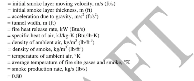
Emergency equipment is necessary to enhance safety in the event of a fire. These equipments are an integral part of modern tunnels (Figure 17.1). The type and amount of equipment is usually based on tunnel type and length, traffic, etc. The equipment covers all facilities necessary in case of fire or some other accident such as: detection and lighting systems, ventilation systems, fixed fire fighting systems, emergency telephone, fire extinguishers, equipment to close the tunnel, radio transmissions, loudspeakers, variable text signs, and emergency exits. Many countries use a tunnel classification system that categorizes tunnels into groups, and specifies the necessary emergency equipment for each group (NFPA 2011 and PIARC 1999).
Fire Development in Tunnels
Fires within confines of underground systems are among the most difficult to extinguish due to restricted space of operation and limited access points for fire fighters; limited emergency exits locations; restricted availability of water supply; and ventilation capabilities.
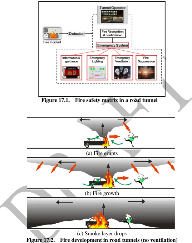
From the beginning of a fire incident, the airflow in the tunnel is considerably modified and becomes highly transient. The modifications are not only due to the fire itself, but also to the emergency ventilation operation, and the change in the traffic in the tunnel. The smoke progress and its degree of stratification depend on airflow, heat release rate, natural ventilation, tunnel geometry and slope and traffic. With no air current in the fire zone, the smoke progresses in a symmetrical way on both sides of the fire. Underneath the smoke layer, fresh air is drawn in towards the fire source in an opposite direction to the spreading smoke. This separation between the hot upper layers and cooler lower layers is termed “stratification”. The combined effects of convective heat exchange with the tunnel walls and the mixing between the smoke and the fresh air layer causes the smoke to cool down and lose its stratification. After a period of typically 5 to 10 min (Heselden 1976) both upstream and downstream sections of the tunnel can be completely filled with smoke (Figure 17.2). The tunnel slope could induce an acceleration of the smoke towards the ascending direction (stack effect).
The tunnel ceiling restricts impinging flames, from a substantial fire, to travel horizontally forming a hot layer at the ceiling. For example, a flame in the open that is 7 m (23 ft) high could give flames
10-20 m (32.8- 65.6 ft) long when placed in a 5 m (16.4 ft) high tunnel (Heselden 1976). This elongation arises due to the much slower entrainment of air into the horizontally traveling flame compared to the case in which the flame is travelling vertically. In this case, the turbulent eddies are opposed by buoyancy forces and the rate of air mixing is reduced. In addition, the mixing with the horizontal flame can only occur on one side of the flame. Consequently, a hot smoky flow of combustion products under the ceiling will travel for long distances with limited mixing of air into the layer. This will inhibit dilution of the smoke resulting in high concentrations of smoke and combustion products (for most fuels, the gases should be diluted with approximately 100-1000 times (Heselden 1976) their weight with air before they can be brought to a condition which can be tolerated by human beings). This will seldom be possible in tunnels, complicating egress and fire fighting processes.
In a tunnel environment, the type of fuel and the resultant fire load can vary enormously due to the different types of materials being transported. Also, multiple fires can occur as the incident
escalates. The fire, for example, may undergo an incubation period (slow burning) of 3 and 8 min (Kashef et al 2011) due to the ignition of a poor combustible material. On the other hand, an
explosion can be expected in the event of ignition of large loads of highly flammable hydrocarbons. The burning rates for most fires in tunnels will not be controlled by the rate of air supply to the fire. Rather, the burning rate and hence the heat release rate will depend on the amount of fuel and its characteristics. In fact, higher burning rates may be possible in tunnels than in open air due to the intense heat fed back from the heated walls and ceiling and from the hot gas layer flowing away from the fire.
During the initial stages, the traffic in the tunnel is modified. First, the fire creates an obstacle to the traffic. In the second stage, barriers and/or traffic lights will be operated to stop the traffic upstream of the fire and at tunnel portals. After vehicles present in the tunnel upstream of the fire are stopped, they create an obstacle to the airflow in the tunnel and thus reduce the performance of the ventilation system. These changes in the traffic flow also modify the piston effect induced by the circulation of the vehicles in the tunnel.
Backlayering
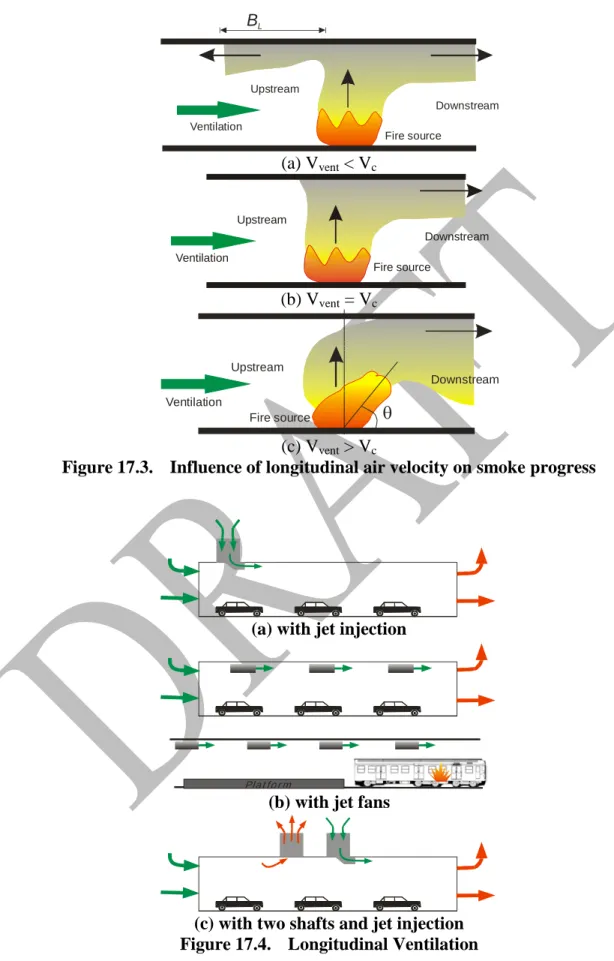
The backlayering phenomenon is defined as the situation in which the hot smoke layer moves against the provided ventilation upstream of the fire (Figure 17.3a) creating an environment that poses a danger to both tunnel users and emergency responders. If the airflow has a high enough velocity, Vvent, the longitudinal airflow pushes the smoke to move to the downstream of the fire, while at the upstream side the progression of the smoke layer is slowed down. Further increase of the longitudinal airflow velocity will at a certain value, called critical velocity, Vc, completely stop the backlayering and reduce the concentration of smoke (Figure 17.3b). In this case, smoke
stratification is unlikely. With higher ventilation velocities the smoke stratification will be completely disrupted (Figure 17.3c).
The occurrence of backlayering depends on many factors including the intensity of fire, the grade and geometry of the tunnel, and the velocity of the ventilating air approaching the fire.
Smoke layer speed and depth
The smoke layer initial moving velocity, uso, and initial thickness, dso, for the situation where no longitudinal ventilation is provided can be estimated from (Heselden 1976):
W u m d W C T Q gT C u so s s so P F s so ρ ρ = = ∞ ∞ 3 1 2 (17.1) where:
uso = initial smoke layer moving velocity, m/s (ft/s) dso = initial smoke layer thickness, m (ft)
g = acceleration due to gravity, m/s2 (ft/s2)
W = tunnel width, m (ft)
Q = fire heat release rate, kW (Btu/s)
Cp = specific heat of air, kJ/kg·K (Btu/lb·K) ρ∞ = density of ambient air, kg/m3 (lb/ft 3) ρs = density of smoke, kg/m3 (lb/ft3) T∞ = temperature of ambient air, °K
TF = average temperature of fire site gases and smoke, °K
s
m = smoke production rate, kg/s (lb/s)
Cs = 0.80
Table 17.1 shows some information on the smoke layer speed and thickness calculated by Heselden (Heselden 1976) for hypothetical tunnel for different fire sizes.
The speed of movement of the smoke layer dictates to a great degree the minimum distance for the smoke to be extracted through the ceiling vents.
Methods of Smoke Management
In a tunnel environment, various smoke management strategies can be employed to achieve the goals of offsetting buoyancy of the smoke and external atmospheric conditions and to prevent backlayering. These strategies include extraction, transport, control direction of movement, and dilution. Smoke can be extracted using: localized extraction points, a transverse, or a semi-transverse ventilation system.
Dilution is usually an efficient method for normal operation, in which case the objective is to maintain air quality and visibility. It can increase tenability by reducing concentrations of toxic gases. During emergency operation, smoke management is ideally achieved by removal of vitiated air, for example by the extraction of air and smoke. Hence, vitiated air is replaced by clean or smoke-free air, which is either supplied mechanically or drawn in through the portals.
Smoke layer can be transported by creating a longitudinal airflow along the length of the tunnel by introducing or removing air from the tunnel at a limited number of points. This approach is the most effective method of smoke control in tunnels with unidirectional traffic.
Visibility
In a tunnel environment, visibility tends to be the most restrictive criterion for tenability.
Evacuation can be significantly hindered by poor visibility. For acceptable visibility and therefore safe evacuation, reliable and robust control of airflow velocity is essential at all times.
Smoke stratification in tunnels is a transient phenomenon that typically lasts 5 to 10 min. Stratified smoke layer allows evacuees adequate visibility in the region under the smoke layer. Thus,
maintaining the stratification of the smoke for the longest period of time is essential for tunnel users to rescue themselves (self-evacuation phase).
Visibility can be estimated based on the smoke optical density (δ). The parameter δ indicates level of smoke obscuration. The higher the value of δ is, the higher the smoke obscuration is and the lower the visibility is. The visibility, S, may be calculated from δ as follows:
α K S = (17.1) where: α = extinction coefficient, m-1 (ft-1) = 2.303 δ
K = proportionality constant, dimensionless (8 for illuminated signs, 3 for reflected signs and building components in reflected light)
S = visibility, m (ft)
The extinction coefficient can be expressed in terms of the specific extinction coefficient, αm (m2/g) and mass concentration of particulate, mp, g/m3 (lb/ft3):
p mm α α = (17.2) where: s c p f p V H Qt y K m ∆ = (17.3) where:
yp = particulate yield (dimensionless) t = time from ignition, s
Vs = volume of smoke in the space, m3 (ft3) ∆Hc = heat of combustion, kJ/kg (Btu/lb) Kf = 1000 (1)
Thus Equation 17.1 can be written as:
Qt y K V H K S p m f s c α ∆ = (17.4)
The NFPA 502 (NFPA 2011) defines the smoke obscuration levels that should be considered to maintain a tenable environment for periods of short duration. Smoke obscuration levels should be continuously maintained below the point at which a sign illuminated at 80 lx or equivalent
brightness for internally luminated signs is discernible at 30 m, and doors and walls that are discernible at 10 m. PIARC (PIARC 1999) recommends maintaining a minimum visibility of 7 to 15 meters (23-49 ft) for evacuation and fire fighting operations. For more information about visibility, see Chapter 6.
Exits and Other Safety Facilities
Road Tunnels
For Tunnels with unidirectional traffic (two tubes or more), evacuees could escape the fire through tunnel portals on foot; cross-passage between tunnel tubes; direct communications to the open; or through separate escape corridors. The escape corridors should be lighted and have a special ventilation system.
The most common escape route in two tube tunnels is through cross-passages between the two tubes. The distance between cross-passages should depend on traffic density and emergency rescue scenarios, for instance 100 – 200 m (328-656 ft) in cities. This distance should be designed so that people can walk to the nearest exit before smoke reduces visibility. When such cross-connections are used, the tunnel operator must consider that people will walk into the second tube. As a
consequence the traffic in this other tube must be stopped immediately. All cross-connections have to be closed by doors in order to prevent the circulation of smoke to the unharmed tube.
It is very important to sign all emergency possibilities with internationally standardized signs. The signs should have the international exit symbol used in buildings and show direction as well as distance to the nearest escape point. The signs should be internally lighted and connected to an UPS (Uninterrupted Power Supply) or have a battery backup. In high traffic tunnels, there should be a minimum safety lighting connected to an UPS. In low traffic tunnels with no UPS, one of every three or four tunnel lights should be fitted with a battery backup. In tunnels with heavy traffic, there should also be a separate system of evacuation lights (marker lights). These lights should be placed as low as possible on the sidewall (1 m or lower) and the distance between the lights should be 25 m or less. All evacuation systems should be kept always lighted to educate drivers and show that the systems are in working order.
Rail and Subway tunnels
In subway systems, the train on fire should, if possible, be sent to the closet station to facilitate the evacuation from the train directly to the station platform. Other nearby trains should be stopped to eliminate the piston effect of moving trains and shift smoke control entirely to the ventilation systems. If the evacuation is taking place away from the station, traction power should be de-energized on the involved track so that evacuees and first responders are not at risk. Furthermore, adjacent tunnels should be kept available for a rescue train or a fire department access train in the event that the train is stranded in the tunnel. The rescue train can expedite evacuation of passengers and transport of first responders to the scene.
NFPA 130 (NFPA 2010) requires that each vehicle shall be provided with a minimum of two means of emergency egress on the sides or at the ends and that Emergency exits shall be provided so that the maximum travel distance is less than or equal 381 m (1250 ft).
Smoke Management Systems in Tunnels
All tunnels require ventilation to maintain acceptable levels of contaminants produced by vehicle engines during normal and congested traffic operation, and to remove and control smoke and hot gases during a fire emergency (emergency ventilation). The ultimate goals of smoke management systems are to:
• provide an environment sufficiently clear of smoke and hot gases to permit safe evacuation; and,
• allow relatively safe access for rescue services as a function of actual fire scenario. In designing the smoke management systems, one should differentiate between two phases. The first phase, called “self-evacuation phase”, occurs immediately after the fire incident being detected and in which the tunnel users commence their evacuation to the nearest exit or safe shelter. The self-evacuation case could last between 4 to 15 min depending on the fire severity, tunnel environment, users’ experience with these situation, and availability of exits. The second phase, called “assisted-evacuation and firefighting phase”, occurs upon the arrival of emergency services to the fire scene. The strategies of smoke control and management may be completely different during these two phases.
Establishing airflow requirements in the tunnel and consequently the capacity of the ventilation system are challenging due to the difficulty of controlling many variables (Kashef and Benichou 2008 and Kashef et al 2009). Among those variables are the possibility of occurrence of many vehicle combinations, combustible loads and traffic situations during the lifetime of the facility. Smoke management in tunnels can be achieved using either natural or mechanical systems.
Natural Ventilation Systems
The consideration of natural smoke venting in the design of new tunnels is gaining more importance with the continued drive toward environmentally sustainable infrastructures to reduce energy
consumption and save costs.
Natural systems count on the pressure differential created by the piston-effect of moving vehicles, the meteorological conditions (external wind, temperature differentials between the portals) and differences in elevation to produce airflow through the tunnel. The created pressure must be large enough to overcome tunnel resistance and is therefore function of tunnel length, cross-sectional geometry, wall roughness, number of vehicles in the tunnel, and air density. Any change in meteorological and operating conditions significantly influence the performance of natural ventilation systems.
Natural and traffic-induced ventilation is adequate for relatively short tunnels and tunnels with low traffic volume (or density). The use of natural ventilation for long and heavily traveled tunnels should be carefully investigated to assure its reliability. Otherwise, mechanical ventilation systems should be used.
Mechanical Ventilation Systems
Mechanical ventilation systems use series of fans to produce airflow and ducts and dampers to distribute this airflow. Regardless of mechanical ventilation equipment, the natural effects
mentioned above are present in all tunnels to a varying extent. A mechanical ventilation system is, generally, classified based on the direction of airflow it creates in the tunnel. There are two basic types of ventilation airflow systems applied in transport tunnels: longitudinal and transverse. Longitudinal ventilation systems produce longitudinal airflow in the direction of the tunnel axis. Whereas, transverse ventilation systems produce airflow that is perpendicular to the tunnel axis in the plane of a cross-section. The choice of what ventilation system to use depends on several parameters that include: tunnel length, cross-section and grade; meteorological conditions (prevailing wind and temperature); traffic type, direction and volume; design fire size; and construction cost.
Longitudinal ventilation
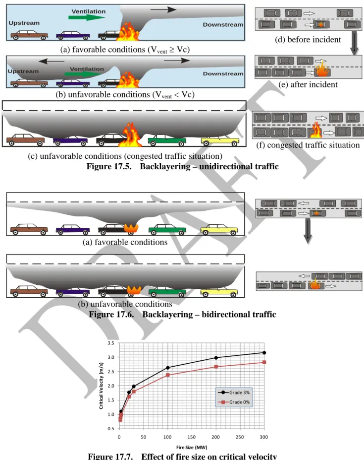
The longitudinal ventilation system (Figure 17.4) creates a longitudinal flow along the roadway tunnel by introducing or removing air from the tunnel at a limited number of points. The ventilation is provided either by injection (Figure 17.4a), by jet fans (Figure 17.4b), or by a combination of injection or extraction at intermediate points in the tunnel (Figure 17.4c). The longitudinal form of ventilation is the most effective method of smoke control in a transport tunnel with unidirectional traffic. In a number of situations, if a longitudinal ventilation strategy is adopted, it is necessary to provide massive extractions points of smoke.
In the event of a fire in a unidirectional tunnel (Figure 17.5d), it is usually assumed that the traffic ahead of the fire will proceed to the exit portal and the traffic behind the fire will come to a stop (Figure 17.5e). The ventilation system should therefore be operated to force the smoke and hot gases in the direction of the empty tunnel to provide a clear and safe environment behind the fire for evacuees and fire fighters. In this case, the main measure of the adequacy of the system for smoke management is its ability to prevent backlayering (Figure 17.5a and b).
The challenges occur in a tunnel that is congested (Figure 17.5f), and so the simple philosophy described above would not be achievable. As a consequence, users may be on either side of the fire limiting the ability of a longitudinal system to properly manage the smoke. In this case, it is crucial to initially limit the longitudinal air current in order to promote smoke stratification and allow users to evacuate underneath the smoke layer in the self-evacuation phase. Subsequently, the strategy of pushing the smoke in one direction can be applied to allow for the intervention of rescue and firefighting services.
As the length of the tunnel increases, excessive air velocities could be expected in one or a few locations across the tunnel. Moreover, in the event of a fire, smoke could be drawn throughout the entire length of the tunnel downstream of the fire.
Critical velocity
The ventilation system must generate sufficient longitudinal air velocity to prevent backlayering of smoke. The air velocity necessary to prevent backlayering of smoke over the stalled motor vehicles is the minimum velocity needed for smoke control in a longitudinal ventilation system and is known as the critical velocity. The critical velocity depends on the fire heat release rate (fire size), the slope, and the tunnel section
geometry. The critical velocity, minimum steady-state velocity, is used to define the fan requirements for smoke control from possible fires and can be determined by the simultaneous solution of Equations (17.5) and (17.5) (Kennedy et al 1996): 3 1 2 1 = ∞ P F c AT C gHQ K K V ρ (17.5) ∞ ∞ + = T AV C Q T c P F ρ (17.6) Where:
Vc = the critical velocity, m/s (ft/s)
g = acceleration due to gravity, m/s2 (ft/s2)
H = tunnel height, m (ft)
A = tunnel cross-sectional area, m2 (ft2)
Cp = specific heat of air, kJ/kg·K (Btu/lb K) ρ∞ = density of ambient air, kg/m3 (lb/ft3)
T∞ = temperature of ambient air (°K)
TF = average temperature of fire site gases (°K) K1 = constant
= Fr-1/3
Fr = The Froude Number for a Flow ventilating a fire = 4.5 K2 = grade factor = 0.80 %) ( 0374 . 0 1+ grade
If the longitudinal air velocity is much greater than the critical velocity, the high flow rates may have the advantage of reducing temperature and decreasing toxicity in the tunnel. However, they will completely destroy the smoke stratification and may cause the fire to grow faster to higher heat release rates. Furthermore, excessive longitudinal air velocity can lead to a faster fire spread among vehicles trapped in the tunnel.
As shown in Figure 17.7, the critical velocity increases rapidly with the fire size up to about 30 MW (2.843 x 10⁴ Btu/s) and then only increases slightly with increased heat-release rate. The same trend is true for different tunnel grades with higher values of the critical velocity corresponding to higher grades for the same fire size (e.g. for a 100 MW (9.478 x 10⁴ Btu/s) fire and grade of 3%, Vc = 2.64 m/s (520 ft/min) versus 2.38 m/s (467 ft/min) at 0% grade).
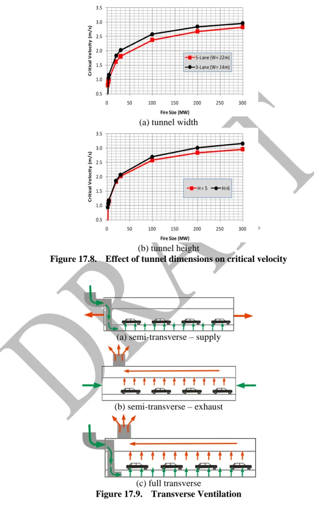
The value of the critical velocity is influenced by the tunnel cross-section dimensions. Reducing the width of the tunnel or increasing its height will increase the value of the critical velocity (Figure 17.8).
While evaluating the required longitudinal ventilation system capacity in case of fire, it must be assumed that a certain number of vehicles can be trapped in the tunnel and their presence reduces the performance of the ventilation system. The number of vehicles trapped can be assessed according to the design mix of traffic (% of passenger cars and heavy vehicles) for the specific tunnels. PIARC guidelines (PIARC 1999) recommended a design airflow velocity of 3 m/s (591 ft/min) for all fires which do not involve a heavy goods vehicle carrying very flammable dangerous goods.
Smoke stratification versus longitudinal airflow
Figure 17.3 shows that the airflow in the tunnel affects not only the backlayering phenomenon, but also the degree of smoke stratification downstream the fire.
If the airflow has a lower velocity, Vvent, than the critical velocity, Vc, the smoke layer will progress the upstream side of the fire causing the backlayering phenomenon to occur. The length of the backlayering distance, BL, can be estimated from (Beard and Carvel 2005):
3 1 3 2 = ∞ ∞C V T Q gH K B vent P B L ρ (17.7)
where KB, is the proportionality constant (0.60-2.2, Beard and Carvel 2005) and Vvent is the airflow velocity in tunnel, m/s (ft/s). Equation 17.7 does not consider other geometrical dimensions (e.g. cross-section shape, tunnel width, or tunnel slope) than the height of the tunnel.
If the approaching airflow has a relatively higher velocity, Vvent, than the critical velocity, the longitudinal airflow will greatly tilt the fire plume pushing the smoke to move to the downstream of the fire where the smoke stratification will be completely disrupted (Figure 17.3c). The degree of deflection of the plume depends on both the approaching airflow velocity and the plume upward velocity. Raj (Raj et al 1979) suggested the following relationship to calculate the plume deflection of LNG pool fires: 2 1 3 1 2 sin − − ∞ ∞ ∆ = c f p vent H T c w V πρ ρ θ (17.8)
where ρ∞ and ρfare densities of ambient air and fuel vapor, kg/m3 (lb/ft3), respectively, and w is the characteristics plume velocity, m/s (ft/s), and may be estimated from (McCaffrey 1976):
5 / 1 c Q C w= θ (17.9)
where Qc is the convective portion of the total heat release, kW (Btu/s) and Cθ is 1.9 (6.301). For example, for a propane pool fire size of 20 MW (1.896 x 10⁴ Btu/s), Qc ≈ 14 MW (1.327 x 10⁴
Btu/s), a ventilation airflow speed of 3.0 m/s (591 ft/min) will bend the plume by θ ≈ 70o
.
The deflection of plume and the disturbance of the smoke layer should be carefully considered as it can create hazardous conditions downstream of the fire. It could greatly impede the evacuation and promote the fire spread to nearby objects due to direct flame impingement or elevated levels of irradiance. Depending on the level of irradiance, the minimum separation distance, R, between vehicles to minimize fire spread can be calculated from (NFPA 92B 2011):
q Q R ′′ = π 12 (17.10)
where q ′′is the incident radiant heat flux required for piloted ignition, kW/m2 (Btu/s ft2) Transverse ventilation
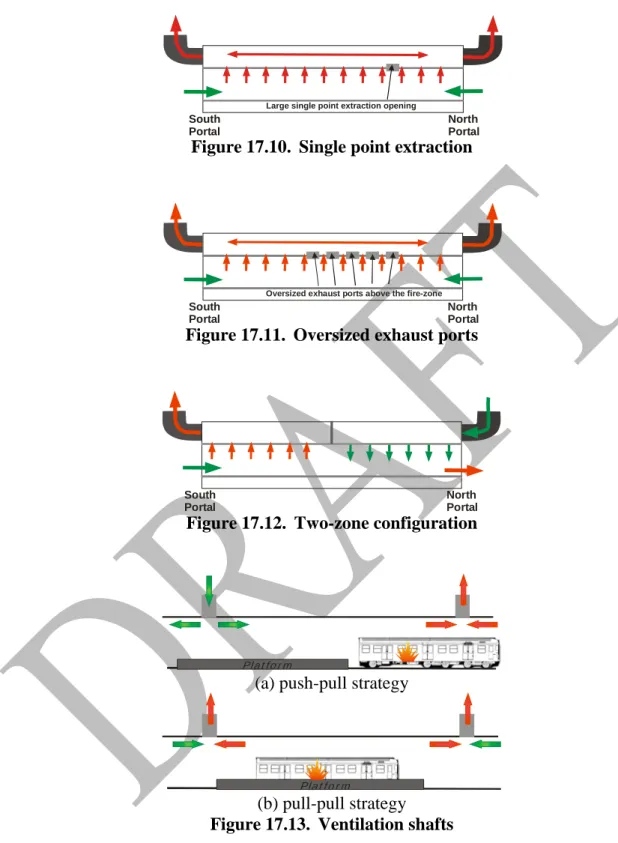
A tunnel that is relatively long, has a heavy traffic flow or is a bidirectional requires different schemes of ventilation than the longitudinal method to properly manage the smoke. Options include semi-transverse ventilation and full transverse ventilation. The main strategy adopted for these systems to manage the smoke is by maintaining smoke stratification near the fire and extracting it from the ceiling or from high openings along the tunnel wall(s). In this approach, longitudinal airflow velocities must to be kept at low magnitudes.
In designing these systems, means to avoid the occurrence of the plugholing phenomenon should be carefully considered. Plugholing refers to a situation where an exhaust fan has such a large capacity that it creates a hole in the smoke layer, exhausting clean air from below the smoke layer as well as
smoke and therefore reducing the efficiency of smoke extraction. To sustain smoke layer
stratification, the smoke exhaust rate, Es, m3/s (ft3/min) should be maintained lower than (Heselden 1976): 2 / 1 2 5 ∆ = ∞ F F s s s T T T gd K E (17.11)
where ds is the thickness of the smoke layer in meter (ft) and Ks is constant, 1.7 (102). Semi-transverse systems
A Semi-transverse ventilation system can be either a supply or an exhaust system (Figure 17.9a and b). This type of ventilation system induces (supply system Figure 17.9a) or collects (exhaust system Figure 17.9b) air uniformly throughout the length of a road tunnel in a duct fitted with supply outlets spaced at predetermined distances. Semi-transverse ventilation is normally used in tunnels up to about 2,000 m (6562 ft). Beyond that length, the tunnel air speed near the portals becomes excessive. This type of ventilation has the advantage of being less affected by
atmospheric conditions since the tunnel airflow is fan-generated.
For Semi-transverse ventilation and in the normal mode of operation, fresh air is best introduced at the vehicle exhaust pipe level to dilute the exhaust gases immediately. An adequate pressure differential between the duct and the roadway must be generated and maintained to counteract the piston effect induced by the traffic flow and adverse atmospheric winds.
In emergency situation, e.g. if a fire occurs in the tunnel, initially the supply air dilutes the smoke. Upon the arrival of fire fighters to the tunnel, the system should be operated in the emergency mode mode such that fresh air enters the tunnel through the portals and smoke exits through the ceiling, hence creating a tenable environment during the assisted evacuation and firefighting phases. To implement this kind of smoke management strategy, this system should have ceiling or at the top of the walls exhaust vents and reversible fans. The reversible fans are essential to be able to operate in the supply mode during normal operations and in the exhaust mode during emergencies.
Full transverse ventilation
Full transverse ventilation (Figure 17.9c) is used in extremely long tunnels (more than 2000 m (6562 ft) long) and in tunnels with heavy traffic volume. This ventilation system is usually balanced system and comprises both supply and exhaust ducts to achieve uniform distribution of supply air and uniform collection of vitiated air throughout the tunnel length. Consequently, this configuration produces a uniform pressure along the tunnel length with no longitudinal airflow being generated except that created by the traffic piston effect.
An adequate pressure differential between the ducts and the roadway should be maintained to ensure proper air distribution under all ventilation conditions. In the event of a fire, the exhaust fan should attain its maximum available capacity while the supply should be maintained at a relatively low capacity. This scheme ensures that the stratified smoke at the ceiling remains at that higher elevation and is extracted by the exhaust ducts without mixing with the lower fresh air. In this way, a tenable environment could be maintained in the tunnel for firefighting and emergency egress. Smoke management strategies should be configured such that smoke is extracted in the fire zone. The objective is to limit the smoke spread within the extraction zone and enable safe evacuation on both sides of the fire. The extraction zone should be as short as practicable while still covering the
fire area, to maximize airflow to the affected location. The extraction rate is usually estimated as 150% of the smoke-production rate of the design fire at a distance of 100 m (328 ft) from the fire. Traditionally, the extraction rate is about of 2½ to 4 times the tunnel cross section (APTA 2010). Sufficient air needs to be provided in the direction of the extraction point (both upstream and downstream) to control the smoke flow and maximize the extraction efficiency.
This method is essential in case of rescue from a fire in a tunnel with bi-directional traffic or traffic congestion. Some systems employ remotely controlled dampers that enable the point extraction of smoke around the fire. It should be noted that the construction and maintenance costs for these systems are higher than for longitudinal systems. Moreover, a larger design fire requires larger duct sizes impacting the resulting investment costs. Careful consideration should be given for the
maintenance of dampers in areas of extreme weather (e.g. cold climates). Other Mechanical ventilation systems
The ventilation systems described earlier could be combined into a hybrid system to address a specific problem in a tunnel. A few modifications can be made to improve the performance of these systems. Among these are: single point extraction and oversized exhaust ports.
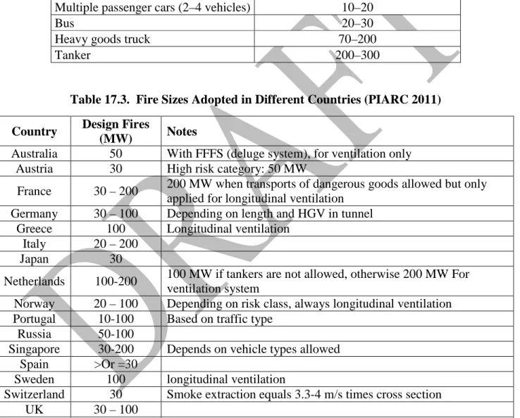
Single point extraction
A single point extraction could be added to a transverse system with large openings to the exhaust duct (Figure 17.10). These openings include devices that can be operated during a fire emergency to extract a large volume of smoke as close to the fire source as possible. Tests conducted as a part of the Memorial Tunnel Fire Ventilation Test Program “MTFVTP” (FHWA 1999) concluded that this concept is effective in reducing the temperature and smoke in the tunnel. The size of openings tested ranged from 9.3 to 27.9 m2 (100 to 300 ft2).
Oversized exhaust ports
These (Figure 17.11) are simply an expansion of the standard exhaust port installed in the exhaust duct of a transverse or semi-transverse ventilation system. Two methods can be used to create such a configuration. One is to install on each port expansion a damper with a fusible link; the other uses a material that when heated to a specific temperature melts and opens the airway. Several tests of such meltable material were conducted as part of the Memorial Tunnel Fire Ventilation Test Program but with limited success.
In addition, other modifications could be implemented for the transverse ventilation system to allow for zone or two-zone ventilation. In the two-zone configuration, as opposed to the single-zone ventilation, the tunnel is divided into two ventilation single-zones such that one half of the tunnel acts as a supply zone and the other half as an exhaust zone (Figure 17.12).
Ventilation shafts
In many railway and subway tunnels, ventilation shafts are used, among other functions, to manage the smoke during a fire event. They could be used to supply fresh air or exhaust smoke out the tunnel. Traditionally, two main ventilation strategies could be used, depending on shaft design and location, fire location, the “push-pull” and “pull-pull” schemes. In the push-pull strategy (Figure 17.13a), the fresh air is supplied through the shafts upstream of the fire and smoke is pulled through shafts downstream of the fire. As such a longitudinal is created across the fire to direct smoke towards outside the tunnel. In the other ventilation scheme, the pull-pull scheme (Figure 17.13b), the smoke is extracted from either sides of the fire.
On-site Evaluation of Ventilation Systems Performance
Fire tests can be carried out on site to verify the adequacy of the ventilation systems and to define more precisely the operating instructions to meet the safety objectives (Kashef et al 2003). Test configurations (fire location, initial air velocity in the tunnel and fire heat release rate) must be designed to take into account as many situations as possible. If only a few configurations can be tested, it is advisable to choose those that are a priority and most unfavorable with regards to user safety.
Onsite fire tests can prove to be valuable as a commissioning tool. A number of operational defects can be identified in the fire tests that could not otherwise be identified in the normal commissioning process. In particular, the communication or lack of communication between systems such as smoke detection systems, smoke exhaust fans, smoke dampers and emergency warning systems. In
addition, obstructions left in air ducts or faulty wiring of fans and dampers can be recognized. Onsite fire tests are delicate operations because they must be carried out before the opening of the tunnel or during its operation, with tight time schedules. It is thus necessary that these tests be led correctly to minimize disruptions and maximize safety.
Procedures to protect people must be established before the tests. Protection also relates to both the equipment that can be isolated and the structure of the tunnel, which should not be exposed to excessive temperatures. In other words, security management must be considered in the design of the tests. The fire heat release rate is inevitably limited and the scenarios must take into account the protection requirements. In the case of a fire test during operation in a tube where traffic is
maintained in the other tube, it is necessary to ensure that smoke is not recycled in the tube open to traffic.
Measurements
Measurements have two objectives:
Monitoring the temperatures during each test. This information can be used to manage safety during the test.
Monitoring airflow velocity, smoke stratification, visibility, and backlayering. The first objective requires the installation of thermocouples on exposed places in the fire zone (equipment and structure of the tunnel). The second objective requires a methodical approach in which it is necessary, before the tests, to identify the phenomena to be characterized. At the end of this analysis, it is necessary to determine the nature, location and number of sensors to be installed in the tunnel.
Fire source
Different sources of smoke can be used to represent fires in tunnels; cold smoke, pool fires, and real fires. The use of smoke-producing products only is not representative of a fire. The production of heat by the fire is not taken into account. This limits the representation of the fire phenomena in terms of critical velocity and natural smoke stratification. This approach is not recommended to establish operating instructions because the phenomena related to the presence of a real fire are not reproduced.
Realistic fires generally use wrecks of road vehicles. The heat release rate developed by this type of fire is well known. Second order variations such as, turbulence or the chaotic emissions of puffs of
smoke, result in a smoke behavior that is much more difficult to characterize and introduce substantial differences compared to calibrated fires tests.
Pool fires and hot smoke tests generally involve hydrocarbon pool fires (heptane or fuel oil). These fires are well known. The advantage of these fires is their stability and therefore leads to well-characterized situations that emphasize the effect of ventilation on smoke behavior (Kashef and Benichou 2008). With hydrocarbon fires, it is generally possible to reach several steady state situations during the same fire test, and thus to test various aerodynamic configurations.
Design Fire
Design fires are an intrinsic part in designing tunnels to withstand fires. They provide,
quantitatively, the fire characteristics that are used to establish the sizing of equipment in tunnels and the scenarios to consider when developing emergency response plans. They are also used, indirectly, when considering the impact of fires on the structure. As such, design fires form the base input for emergency ventilation, evacuation, and structural design analyses.
A design fire is an idealization of a real fire that might occur in a tunnel and is generally defined in terms of heat release rate, and species output as functions of time. It is a set of data that provides the actual fire characteristics such as, ignition sources, nature and configuration of the fuel, fire growth, peak heat release, production rates of combustion products (smoke CO, CO2, etc.) and
extinction. For the design purposes, it is necessary to choose a typical design fire corresponding to the traffic type and pattern in the tunnel and whether hazardous transports are permitted.
A prescriptive approach has traditionally been adopted in which a specific fire size, usually the peak heat release rates depending on the type of vehicle (passenger cars, buses, heavy goods vehicles, pool fires, etc.), is chosen as a basis for the tunnel fire-life safety design (Table 17.2 and Table 17.3). The adequacy of the design fire sizes used for the design of fire protection systems used in road tunnels was seriously questioned following the occurrence of major fire catastrophes in late 1990’s. This has promoted the shift from prescriptive to performance-based regulations.
Performance-based designs are usually based upon explicitly stated objectives that allow the freedom to develop innovative designs satisfying these objectives. Such innovative designs often lead to lower fire protection costs.
The performance-based design approach makes possible the evaluation of the tunnel fire safety as a whole. An important step in the performance-based design is the establishment of possible fire scenarios. Different fire scenarios are created to instigate the design analyses of emergency
ventilation, egress, structural, and fire safety tunnel equipment (e.g. detection and fixed fire fighting systems). A design fire scenario describes qualitatively the key time events following the ignition of a fire such as: quantity and characteristics of combustible materials, material arrangement and location, tunnel geometry, environment, fire protection systems, etc. The design fires are the cornerstone in developing such fire scenarios. As such, design fires are the underpinning in conducting a performance-based design.
Different aspects of a design fire are more important to certain types of analysis than others. For example, the peak heat release (PHRR) and burning duration are important to evaluating structural response to fire. The HRR at the end of evacuation and the PHRR are considerations in evaluating tunnel ventilation equipments and is of concern for the life-safety of the fire service during the fire fighting phase. The objective during this phase is to provide tenable conditions for safe firefighting activities.
The early transient stages of fire development during the growth phase affect the conditions in the tunnel during the “self-rescue” phase and therefore are important to life safety analyses. An
understanding of how fast a fire might grow, and the subsequent spread of smoke and hot gases, is a factor in the design of ventilation, suppression, and detection systems as well as the determination of evacuation strategies.
Design fire scenarios
To achieve optimum fire prevention strategy for tunnels, a number of fire scenarios should be considered during the design stage. These should include:
Egress analysis.
Thermal action on structures.
Ventilation systems design and assessment.
The safety of tunnel fire equipment (e.g. detection and fixed fire fighting systems). Each of these scenarios must be well described prior to the design process. Following are some guidelines for their selection and description:
a description of the aim of the scenario, a thorough definition of the fire parameters:
o heat release versus time
o number of vehicles involved: incidents with one vehicle (car, bus, lorry, petrol tanker) or collision incidents of two to three vehicles
the natural ventilation of the tunnel, effective escape and rescue possibilities:
o availability of firefighting equipments (e.g. fire extinguishers) o availability of detection systems
o time of arrival of the fire brigade o availability of emergency exits o ability to control smoke and visibility o possibility of traffic control
the traffic situation encountered when dealing with questions about tunnel ventilation and operation (e.g. stop and go-situation, congested traffic, mode of traffic flow), and
specifications to be fulfilled by material, equipment and structure with regard to fire prevention strategies (e.g. temperature at concrete reinforcement should not exceed 300°C, 572°F).
Worst cases should not necessarily be considered for design when their probability is very low. For instance, very few fires result from a collision while this case leads to the highest heat release rates and temperatures. If the consequences may be catastrophic (e.g. collapse of an immersed tunnel), such very severe scenarios should be taken into account for design.
Numerical Modeling
The applicable NFPA standards for tunnels (e.g. NFPA 502) require engineering analysis for tunnels greater than a certain length, to assist in evaluating whether the smoke and heat layer is properly managed. Traditionally, engineers and designers have shown the compliance with the codes and standards requirements by using one-, two- or three-dimensional numerical models.
One-dimensional models (1D)
One-dimensional models provide simple design tools for the transient calculation of networks. The fundamental equations of fluid thermodynamics are solved, but only one dimension is considered. That means all the conditions are homogeneous in the cross-section. As they cannot take the layering phenomena into account, they cannot be applied in the fire vicinity. Nevertheless these principles seem sufficient for studying the conditions far from the source in an underground road network or a very long tunnel, and for providing boundary conditions to a CFD code in the case where the whole tunnel is not modeled by this latter model.
The appropriateness of such tools for special applications, particularly when the tunnel is wide or high with respect to the physical size of the fire, should be carefully validated. In these situations, the studies in the MTFVTP (FHWA 1999) indicated that these design tools need improvement to better predict the critical longitudinal air velocity required to prevent back-layering and allow for the control of smoke and hot gas spread in a tunnel. Examples of this family of tools include:
SES: The predominant worldwide tool for analyzing the aero-thermodynamic environment of rapid
transit rail tunnels is the Subway Environment Simulation (SES) computer program (DOT 1997). SES is a one-dimensional network model that is used to evaluate longitudinal airflow in tunnels. The model predicts airflow rates, velocities and temperatures in the subway environment due to train movement or fans, as well as the station cooling loads required to maintain the public areas of the station to predetermined design conditions throughout the year. This program contains a fire model that can simulate longitudinal airflow required to overcome backlayering and control smoke movement in a tunnel. The SES program is in the public domain, available from the Volpe National Transportation Systems Center in Cambridge, MA.
TUNVEN: This program solves coupled one-dimensional, steady-state tunnel aerodynamic and
advection equations. It can predict quasi-steady-state longitudinal air velocities and concentrations of CO, NOx, and total hydrocarbons along a road tunnel for a wide range of tunnel designs, traffic loads, and external ambient conditions. The program can also be used to model all common road tunnel ventilation systems (i.e., natural, longitudinal, semi-transverse, and transverse). The user needs to update emissions data for the calendar year of interest. The program is available from the National Technical Information Service (NTIS 1980).
Zone models (2D models)
Zone models are seldom used to study the spread of smoke and temperature in tunnels, but they are commonly used in buildings. They generally describe a room or a corridor as a homogeneous zone where a fresh air layer lies under a smoke layer, each of them having constant characteristics - including their thickness - on the whole zone. The fire, the exchanges between the layers and between the neighboring zones are governed by partially empirical equations.
Such models - relatively flexible - can be investigated on a desk top computer and are well adapted to investigate the smoke and heat propagation in a complex system of communicating rooms. Unfortunately they are not well adapted to studying fires in tunnels, where the main problem is to predict the evolution of the smoke plume inside a large zone, moreover submitted to a longitudinal airflow, whose influence is determining. Few validations have been performed with such models and their success still seems uncertain for tunnel fires.
Computational Fluid Dynamics (CFD) – 3D
CFD modeling techniques are sophisticated and computationally intensive design tools. They can model actual conditions in tunnels and predict three-dimensional patterns of airflow, temperature and other flow variables, including concentration of species, as function of time and space. In areas of geometrical complexity, CFD is the appropriate tool to predict.
SOLVENT: SOLVENT was developed for tunnel ventilation simulation in Phase IV of the
MTFVTP (Parsons Brinckerhoff 2000). The model is applicable to different ventilation modes, including longitudinal ventilation using jet fans, transverse ventilation, and natural ventilation. SOLVENT is geared towards individuals (analysts, designers, and tunnel operators) concerned with fire/life safety in tunnels. The primary objective established for the model was the ability to
simulate the interactive effects of a tunnel fire and the ventilation system to determine the unsafe regions of the tunnel. That is, the regions where the hazardous effects of the fire (smoke and high temperatures) are confined, and how these regions are affected by the ventilation system
configuration, capacity, and operation. The program results have been validated against data from the MTFVTP.
Fire Dynamics Simulator (FDS): FDS (McGrattan et al 2011) is a CFD model of buoyancy-driven
fluid flow from a fire. FDS consists of two computer programs, the first called simply FDS, is a Fortran 90 computer program that solves the governing equations. The second, called smokeview, is an OpenGL graphics program that allows one to visualize the results. All of the input parameters required by FDS to describe the particular scenario of interest are conveyed via one or two text files created by the user. FDS can model pollutant levels outside the portals and around the exhaust stacks of tunnels. Both of these public domain programs are under active development and can be obtained from National Institute of Standards and Technology (NIST).
Other CFD programs, both commercially available and in the public domain, have been used to model fire scenarios in road and rapid transit tunnels and stations, the list of which is too numerous to include here. The strengths and weaknesses of each program should be investigated beforehand, and validation of the results against experimental data or another equivalent program is encouraged.
Detection
The dynamics of smoke movement in tunnels is such that evacuation or rescue operations should start within 5 to 15 min from the start of fire incident. As such, a fire detection system is a critical element of the fire prevention and protection matrix in tunnels. Quick and reliable fire detection allows for timely activation of other elements of the fire protection matrix which may include one or all of the following systems: emergency lighting, public address, emergency ventilation, and fixed fire fighting systems (Figure 17.1). Detection can make the difference between a manageable fire and one that gets out-of-control. On other hand, false or nuisance alarms are not only costly but also can promote a lack of confidence in the reliability of detection systems. Automatic fire
detection has been employed in tunnels for several years.
Detection is conducted based on exceeding threshold values for a prescribed duration (Kashef et al 2008). It is useful to include the rates of change of the measurements in the evaluation. In this context it is important to divide the tunnel into well-defined sections to enable accurate allocation of an incident to the operator. Particularly when using smoke extraction, the location of the fire needs to be detected in order to incorporate the correct response with respect to ventilation control.
Normally, smoke detection is less accurate in determining the location of the fire than is a high-temperature alarm using a linear heat detector. Moreover, the reaction due to several independent fire detectors by one or more systems has to be considered. This concerns the detection of moving fire sources (moving trains on fire) as the location of the initial detection of the fire might not be the same as the location where the vehicle comes to a standstill (in particular information retrieved from VID and smoke detection).
Performance criteria
Many factors affect the performance of detection systems in the harsh environment of tunnels. Pollution, wind speed, tunnel geometry, fire type, size and location, traffic congestions are a few examples. Various types of detection systems are affected with different degree by these factors. Performance of fire detection systems is usually evaluated based on the requirements for tunnel protection (Kashef et al 2008):
• Response capability to tunnel fire incidents involving fire size, type, growing rate and location (measuring parameter: time (minute));
• Locating capability to the fire position in the tunnel (measuring parameter: distance (meter));
• Monitoring capability of some systems to a fire incident (i.e. fire growing and developing direction in the tunnel);
• As well as their reliability in harsh tunnel environments, including their nuisance alarm immunity and requirements for maintenance and operating costs.
Available Detection Technologies
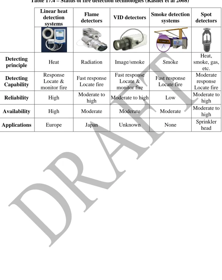
There are a range of methods available to detect fire and smoke within tunnels. Each system is designed to detect a certain fire-related signature. There are five types of currently available technologies: linear heat detection, video image detectors (VID), flame detectors, smoke and heat detectors, and spot heat detectors. Fire detection systems should be selected to support the fire safety goals and objectives and the overall fire safety program, which can include notifying occupants to allow for safe evacuation, modifying tunnel ventilation or operations, and notifying emergency responders.
Table 17.4 lists the main five types of detection technologies, their principal of detection, along with general assessment of their performance in road tunnels. All these systems are required to have a guaranteed back-up of operational elements (redundancy), units and the system as a whole. It is a prerequisite that the system ensures execution of pre-defined tasks if a total breakdown situation comes up.
Nomenclature
A = tunnel cross-sectional area, m2 (ft2)
Cp = specific heat of air, kJ/kg·K (Btu/lb·K) dso = smoke layer initial thickness, m (ft) ds = smoke layer thickness, m (ft) Es = smoke exhaust rate, m3/s (ft3/min) g = acceleration due to gravity, m/s2 (ft/s2)
H = tunnel height, m (ft)
K = proportionality constant
K2 = grade factor
KB = proportionality constant
mp = mass concentration of particulate, g/m3 (lb/ft3) ṁs = smoke production rate, kg/s (lb/s)
Q = fire heat release rate, kW (Btu/s)
Qc = convective portion of the fire heat release rate, kW (Btu/s)
q″ =incident radiant heat flux required for piloted ignition, kW/m2 (Btu/s m2)
t = time from ignition (s)
T∞ = temperature of ambient air (°K)
TF = average temperature of fire site gases (°K) w = characteristics plume velocity, m/s (ft/s) W = tunnel width, m (ft)
V = airflow velocity in tunnel, m/s (ft/s) S = visibility, m (ft)
Vs = volume of smoke in the space, m3 (ft3) Vc = the critical velocity, m/s (ft/s)
yp = particulate yield (dimensionless)
uso = smoke layer initial moving velocity, m/s (ft/s)
Greek
α = extinction coefficient, m-1 (ft-1) ∆Hc = heat of combustion, kJ/kg (Btu/lb) ρ∞ = density of ambient air, kg/m3 (lb/ft3) ρs = density of smoke, kg/m3 (lb/ft3)
αm = specific extinction coefficient, m2/g (ft2/lb) ρf = density of fuel vapor, kg/m3 (lb/ft3)
References
1. Alan Beard and R. Carvel. 2005. “The Handbook of Tunnel Fire Safety”, Thomas Telford Ltd., 1 Heron Quay, London E14 4JD.
2. APTA 2010. “Operational Strategies for Emergency Smoke Ventilation in Tunnels –White Paper”. Standards Development Program SS-SEM-WP-013-10, American Public Transportation Association (APTA) Washington, DC.
3. ASHRAE 2011. “Enclosed Vehicular Facilities”. Chapter 17, ASHRAE Handbook, HVAC Applications.
4. DOT 1997. “Subway environment simulation (SES) computer program Version 4: User's manual and programmer’s manual”. Issued as Volume II of Subway Environmental Design Handbook. Pub. No. FTA-MA-26- 7022-97-1. US Department of Transportation, Washington, DC. Also available from Volpe Transportation Center, Cambridge, MA.
5. Heselden, A J M. 1976. "Studies of fire and smoke behaviour relevant to tunnels". In: Proc. Second International Symposium on the Aerodynamics and Ventilation of Vehicle Tunnels, Cambridge, BHRA, paper J1.
6. Innovative Research, Inc./Parsons Brinckerhoff, Inc. 2000. “SOLVENT Version 1.0”.
7. K.B. McGrattan, H.R. Baum, R.G. Rehm, G.P. Forney, J.E. Floyd, and S. Hostikka. 2011. “Fire Dynamics Simulator (Version 5), Technical Reference Guide”. Technical Report NISTIR 6783, National Institute of Standards and Technology, Gaithersburg, Maryland.
8. Kashef, A., Bénichou, N. 2008. "Investigation of the performance of emergency ventilation strategies in the event of fires in a road tunnel - a case study". Journal of Fire Protection Engineering, 18, (3), pp. 165-198.
9. Kashef, A., Bénichou, N. 2008. "Investigation of the performance of emergency ventilation strategies in the event of fires in a road tunnel - a case study". Journal of Fire Protection Engineering, 18, (3), pp. 165-198.
10. Kashef, A., Bénichou, N., Lougheed, G.D. 2003. “Numerical Modelling of Movement and Behaviour of Smoke Produced from Fires in the Ville-Marie and L.-H.-La Fontaine Tunnels: Literature Review”. Research Report, NRC Institute for Research in Construction, 141, pp. 66, (RR-141).
11. Kashef, A., Liu, Z., Lougheed, G.D., Crampton, G.P., Yoon, K., Hadjisophocleous, G.V.,
Almand, K. 2008. "Findings of the international road tunnel fire detection research project," Fire technology - the special issue on smoke control in buildings and tunnels, 45, (2), pp. 221-237. 12. Kashef, A., Liu, Z., Lougheed, G.D., Crampton, G.P., Yoon, K., Hadjisophocleous, G.V.,
Almand, K. 2008. "Findings of the international road tunnel fire detection research project". Fire technology - the special issue on smoke control in buildings and tunnels, 45, (2), pp. 221-237. 13. Kashef, A., Saber, H.H., Gao, L. 2009. "Optimization of emergency ventilation strategies in a
roadway tunnel". Fire Technology Journal, 45, (4), pp. 1-28.
14. Kashef, A.; Viegas, J.; Mos, A.; Harvey, N. 2011. “Proposed idealized design fire curves for road tunnels”. 14th International Symposium on Aerodynamics and Ventilation of Tunnels (Dundee, Scotland 2011-05-11) pp. 1-14.
15. Kennedy, W.D., J.A. Gonzalez, and J.G. Sanchez. 1996. “Derivation and application of the SES critical velocity equations”. ASHRAE Transactions 102(2): 40-44.
16. Lacroix, D., 1998. The New PIARC Report on Fire and Smoke Control in Road Tunnels. In the Third International Conference on Safety in Road and Rail Tunnels, Nice, France, p. 185-97.
17. Massachusetts Highway Department/Federal Highway Administration. 1999. “Memorial Tunnel Fire Test Ventilation Program – Phase IV Report”. Commonwealth of Massachusetts, Central Artery/Tunnel Project.
18. McCaffrey, B.J. 1976. “Purely buoyant diffusion flames: some experimental results”, National Bureau of Standards, NBSIR 79-1910.
19. NFPA 2005. “Standard for Smoke Management Systems in Malls, Atria, and Large Areas”, NFPA 92B, National Fire Protection Association, Quincy, MA.
20. NFPA 2010. Standard for Fixed Guideway Transit and Passenger Rail Systems – NFPA 130, National Fire Protection Association, Quincy, MA.
21. NFPA 2011. Standard for Road Tunnels, Bridges, and Other Limited Access Highways – NFPA 502, National Fire Protection Association, Quincy, MA.
22. NTIS 1980. “User's guide for the TUNVEN and DUCT programs”, Publication PB80141575. National Technical Information Service, Springfield, V A.
23. PIARC 1999. “Fire and Smoke Control in Road Tunnels”, Technical Committee on Road Tunnels, reference 20.05.B, the World Road Association (PIARC).
24. PIARC 2007. “Systems and Equipment for Fire and Smoke Control in Road Tunnels”. Technical Committee on Road Tunnels, the World Road Association (PIARC).
25. PIARC 2011. “Design Fire Characteristics for Road Tunnels”. Working Group 4, Technical Committee on Road Tunnels, C4, Committee on Tunnel Operations, the World Road Association (PIARC).
26. Raj, P., Moussa, A., and Aravamudan, K. 1979. “Experiments Involving Pool and Vapour Fires from Spills of Liquefied Natural Gas on Water”, U.S. Coast Guard Report No. CG-D-55-79.
Example 17.1:
For a tunnel with cross-section dimensions of 5 m in height and 22 m in width (∼5 lanes) and grade of 3%, estimate the value of the critical speeds for a design fire of 100 MW. Assume ambient air temperature 20oC.
Solution: K T s m V K m/s V V K T m/s grade K kg/m RT P K T m A o F c o c c o F o 15 . 578 / 636 . 2 : are Equaionis two the of solutions final the : 2 & 1 Eqs in T and V of values iterating after 609.44 : T new the g calculatin 2, Eq. in value the using 373 . 2 15 . 943 * 110 * 1006 * 204 . 1 10 * 5 * 81 . 9 09 . 1 * 606 . 0 : be will of value new the 52 . 793 15 . 293 110 * 5 . 1 * 1006 * 204 . 1 10 then , 5 . 1 V assume 09 . 1 %) ( 0374 . 0 1 204 . 1 15 . 293 * 287 101325 15 . 293 15 . 273 20 110 22 * 5 F c F 3 1 8 8 c 80 . 0 2 3 2 = = = = = + = = = + = = = = = + = = = ∞ ∞ ∞ ρ
Figure 17.1. Fire safety matrix in a road tunnel
(a) Fire erupts
(b) Fire growth
(c) Smoke layer drops
(a) Vvent < Vc
(b) Vvent = Vc
(c) Vvent > Vc
Figure 17.3. Influence of longitudinal air velocity on smoke progress
(a) with jet injection
(b) with jet fans
(c) with two shafts and jet injection Figure 17.4. Longitudinal Ventilation
Fire source Upstream Downstream Ventilation BL Fire source Upstream Downstream Ventilation θ Platform Fire source Upstream Downstream Ventilation
(a) favorable conditions (Vvent ≥ Vc)
(d) before incident
(b) unfavorable conditions (Vvent < Vc)
(e) after incident
(c) unfavorable conditions (congested traffic situation)
(f) congested traffic situation
Figure 17.5. Backlayering – unidirectional traffic
(a) favorable conditions
(b) unfavorable conditions
Figure 17.6. Backlayering – bidirectional traffic
Figure 17.7. Effect of fire size on critical velocity
Upstream Downstream
Ventilation
Upstream Ventilation Downstream
0.5 1.0 1.5 2.0 2.5 3.0 3.5 0 50 100 150 200 250 300 Cr itic al V elo cit y (m /s ) Fire Size (MW) Grade 3% Grade 0%
(a) tunnel width
(b) tunnel height
Figure 17.8. Effect of tunnel dimensions on critical velocity
(a) semi-transverse – supply
(b) semi-transverse – exhaust
(c) full transverse
Figure 17.9. Transverse Ventilation 0.5 1.0 1.5 2.0 2.5 3.0 3.5 0 50 100 150 200 250 300 Cr it ic al V elo cit y (m /s ) Fire Size (MW) 5-Lane (W= 22m) 3-Lane (W= 14m) 0.5 1.0 1.5 2.0 2.5 3.0 3.5 0 50 100 150 200 250 300 Cr it ic al V elo cit y (m /s ) Fire Size (MW) H = 5 H=6
Figure 17.10. Single point extraction
Figure 17.11. Oversized exhaust ports
Figure 17.12. Two-zone configuration
(a) push-pull strategy
(b) pull-pull strategy
Figure 17.13. Ventilation shafts
South Portal
North Portal
Large single point extraction opening
South Portal
North Portal Oversized exhaust ports above the fire-zone
South Portal North Portal Platform Platform
Table 17.1 – Smoke Layer characteristics in A Hypothetical Tunnel (Heselden 1976) Fire Size (MW) 3 10 20 50 100 s m (kg/s) 17 24 35 48 95 uso (m/s) 1.3 2.2 3.0 5.3 6.7 dso (m) 0.7 0.9 1.2 1.7 2.7
Table 17.2. Fire Data for Typical Vehicles (NFPA 502 Table A.10.5.1)
Vehicles Peak Fire Heat–Release Rates (MW)
Passenger car 5–10
Multiple passenger cars (2–4 vehicles) 10–20
Bus 20–30
Heavy goods truck 70–200
Tanker 200–300
Table 17.3. Fire Sizes Adopted in Different Countries (PIARC 2011)
Country Design Fires
(MW) Notes
Australia 50 With FFFS (deluge system), for ventilation only Austria 30 High risk category: 50 MW
France 30 – 200 200 MW when transports of dangerous goods allowed but only applied for longitudinal ventilation
Germany 30 – 100 Depending on length and HGV in tunnel Greece 100 Longitudinal ventilation
Italy 20 – 200
Japan 30
Netherlands 100-200 100 MW if tankers are not allowed, otherwise 200 MW For ventilation system
Norway 20 – 100 Depending on risk class, always longitudinal ventilation Portugal 10-100 Based on traffic type
Russia 50-100
Singapore 30-200 Depends on vehicle types allowed Spain >Or =30
Sweden 100 longitudinal ventilation
Switzerland 30 Smoke extraction equals 3.3-4 m/s times cross section
UK 30 – 100
Table 17.4 – Status of fire detection technologies (Kashef et al 2008) Linear heat
detection systems
Flame
detectors VID detectors
Smoke detection systems
Spot detectors
Detecting
principle Heat Radiation Image/smoke Smoke
Heat, smoke, gas, etc. Detecting Capability Response Locate & monitor fire Fast response Locate fire Fast response Locate & monitor fire Fast response Locate fire Moderate response Locate fire
Reliability High Moderate to
high Moderate to high Low
Moderate to high
Availability High Moderate Moderate Moderate Moderate to
high
Applications Europe Japan Unknown None Sprinkler