Publisher’s version / Version de l'éditeur:
Proceedings of the 2005 International Conference on Powder Metallurgy and Particulate Materials, 2005-06-19
READ THESE TERMS AND CONDITIONS CAREFULLY BEFORE USING THIS WEBSITE. https://nrc-publications.canada.ca/eng/copyright
Vous avez des questions? Nous pouvons vous aider. Pour communiquer directement avec un auteur, consultez la première page de la revue dans laquelle son article a été publié afin de trouver ses coordonnées. Si vous n’arrivez pas à les repérer, communiquez avec nous à [email protected].
Questions? Contact the NRC Publications Archive team at
[email protected]. If you wish to email the authors directly, please see the first page of the publication for their contact information.
NRC Publications Archive
Archives des publications du CNRC
This publication could be one of several versions: author’s original, accepted manuscript or the publisher’s version. / La version de cette publication peut être l’une des suivantes : la version prépublication de l’auteur, la version acceptée du manuscrit ou la version de l’éditeur.
Access and use of this website and the material on it are subject to the Terms and Conditions set forth at
Properties And Processing Of Improved SMC Materials
Gélinas, C.; Pelletier, S.; Lemieux, P.; Azzi, L.
https://publications-cnrc.canada.ca/fra/droits
L’accès à ce site Web et l’utilisation de son contenu sont assujettis aux conditions présentées dans le site LISEZ CES CONDITIONS ATTENTIVEMENT AVANT D’UTILISER CE SITE WEB.
NRC Publications Record / Notice d'Archives des publications de CNRC:
https://nrc-publications.canada.ca/eng/view/object/?id=77380a32-2225-4a70-b89e-3092add10526 https://publications-cnrc.canada.ca/fra/voir/objet/?id=77380a32-2225-4a70-b89e-3092add10526
PROPERTIES AND PROCESSING OF IMPROVED SMC MATERIALS.
C. Gélinas1, S. Pelletier2, P. Lemieux2 and L. Azzi2
1. Quebec Metal Powders Limited, Sorel-Tracy, Québec, Canada 2. Industrial Materials Institute/NRCC, Boucherville, Québec, Canada
ABSTRACT
SMC are insulated iron powders intended for use in replacement of electrical steel sheets in
electromagnetic devices subjected to time varying magnetic fields. Manufactured using the powder metallurgy route with its choice of processing conditions, a range of SMC materials with adequate final properties can be achieved. For instance, two types of SMC powders that differ in
composition and in processing route are herein described. One is an iron-resin composite material, which requires die wall lubrication during compaction and a low temperature curing in air to cross-link the resin and achieve high strength (ATOMET EM-1). The other is an iron/dielectric
composite material in which the dielectric acts as a lubricant during the compaction as well as an electrical insulator after a moderate temperature heat treatment (ATOMET EM-2).
Lately, development works led to improvements in both types of SMC materials, which are presented in this paper. The properties as well as the processing aspects are discussed, especially the compaction and heat treatments.
1. INTRODUCTION
Soft magnetic composites or SMC are iron-based powders specifically engineered for AC magnetic applications. They compete against laminations in various electromagnetic devices including electrical motors. The general principle of these materials is that the iron particles are insulated by a thin organic or inorganic coating or a combination of both. This thin coating acts primarily as an electrical barrier to reduce or suppress Eddy currents in AC applications while allowing magnetic flux path in three dimensions. After consolidation into pressed parts, instead of a conventional temperature sintering treatment, SMC are heat treated at a low temperature in order to achieve a moderate strength and a certain extent of stress relief.
A few years ago, QMP introduced a first type of SMC material called ATOMET EM-1 [1]. This material system has undergone few changes over the years in order to improve its handling and processability at the press. Besides this material evolution, a second material system called ATOMET EM-2 was also developed with improved magnetic performances at low frequency. In this paper, the characteristics of these two SMC materials are described with their mechanical and magnetic properties. Some processing aspects and component application aspects are also discussed.
2. DESCRIPTION OF SMC MATERIALS
The two types of SMC materials manufactured by QMP are based on a high purity water-atomized iron powder that provides the high compressibility required to achieve high densities and good magnetic properties. ATOMET EM-1 is an iron-resin material system that has little internal lubricity capability and thus requires lubrication of the die walls during compaction. The main merit of this material system is its high strength and this is why there is no internal lubricant which negatively affects the strength. After pressing, parts are cured at low temperature (200°C to 325°C) in air to cross-link the resin and achieve the high strength. The improvements that were brought to this material system in recent years addressed the manufacturing of the SMC powder and its processing at the press. For instance, by applying a binder treatment in the manufacturing process the powder handling significantly improved: the flow improved and the apparent density increased while the tendency to dusting was eliminated. These changes combined to the use of an efficient die wall lubrication system (including new high performance external lubricants) also significantly improved the processability of the powder at the press. This aspect will be described in more details in a next section.
A second SMC material, ATOMET EM-2, was developed with the objective of improving the magnetic performances at low frequency. This meant that the material had to sustain a higher temperature during the heat treatment in order to partially stress relieve the parts and reduce the hysteresis losses while keeping Eddy currents at low levels. This SMC is an iron-dielectric material in which the dielectric acts as a lubricant during the compaction and as an insulator after a low temperature heat treatment, typically between 350°C and 475°C. The amount of dielectric in this SMC press-ready mix can be varied in order to meet compaction requirements or magnetic property requirements.
Some characteristics of the two composite materials are given in Table I. Their apparent density and Hall flow rate are similar. The two materials are complementary in terms of electrical
resistivity which is governed by the type and quantity of insulating material and temperature of the heat treatment. While ATOMET EM-1 can be used in a very large range of frequency applications, ATOMET EM-2 is rather intended for applications below 400 Hz and particularly suitable for pressing complex shapes.
Table I. Characteristics of the ATOMET EM-1 and EM-2 materials used for low to medium frequency applications.
Material ATOMET EM-1 ATOMET EM-2
Description Iron-resin Iron-dielectric
Apparent density 3.00 g/cm³ 3.00 g/cm³ Hall flow rate 28 s/50 g 28 s/50 g
Compaction External lubrication Conventional Curing (30 min) 200 - 325°C 350 - 475°C
Resistivity 400 - 600 µ ohm-m 10 - 100 µ ohm-m Applications 50 - 20000 Hz 50 - 400 Hz
3. PHYSICAL AND MECHANICAL PROPERTIES
Like any other powdered metal part, the mechanical and magnetic properties of such SMC
properties were obtained on rectangular bars pressed from ATOMET EM-1 cured at 200°C or 325°C and from ATOMET EM-2 heat-treated at 350°C or 430°C.
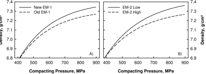
The compressibility of the two SMC materials is illustrated in Figure 1. For the ATOMET EM-1, the compressibility curves for the old and new versions are plotted to show in which extent the new material has improved compared to the old version, especially at high compacting pressures. For instance, at 900 MPa the gain in density is around 0.10 g/cm³ (fig. 1A). In the case of ATOMET EM-2, the compressibility is given for two levels of dielectric content: a low level (0.65%) and a high level (0.90%). Using a low level of dielectric increases the pore free density of the material and the maximum density that can be achieved during compaction. There is a difference of
approximately 0.12 g/cm³ at 900 MPa between the low and high dielectric content ATOMET EM-2 materials (fig. 1B).
Compacting Pressure, MPa
400 500 600 700 800 900 D e n s ity , g /cm³ 6.8 6.9 7.0 7.1 7.2 7.3 7.4 New EM-1 Old EM-1
Compacting Pressure, MPa
400 500 600 700 800 900 D e n s ity , g /cm³ 6.8 6.9 7.0 7.1 7.2 7.3 7.4 EM-2 Low EM-2 High A) B)
Figure 1. Green density as a function of the compacting pressure for the two SMC materials: A) old and new ATOMET EM-1; B) ATOMET EM-2 with a low and a high dielectric content. The measurement of electrical resistivity is a convenient and rapid method to evaluate the extent of insulation between the iron particles in a SMC. Contrary to a wrought material, soft magnetic composites are inhomogeneous materials composed of a conducting phase, the magnetic particles, and an insulating phase, the dielectric. Nevertheless, simple methods such as the four-point contact probe method which measures voltage drop between electrodes can be used. It has been
demonstrated [2] that valuable results are obtained if two criteria are respected: the induced currents must travel a distance significantly larger than the heterogeneity (discrete particles) and throughout the bulk material (not only at the surface). These criteria are achieved by selecting the appropriate probe (electrode spacing) and specimen geometry.
In SMC, the insulation is dependent on the materials system, the density and the heat treatment temperature. Typical values measured using the four-point method are plotted in Figure 2 as a function of the density for the two materials heat treated at different temperatures (note the different resistivity scale in the 2 graphs). As mentioned previously, the resistivity of ATOMET EM-1 is much higher than that of ATOMET EM-2 and as expected, the values decrease with an increase of the temperature of the heat treatment. The resistivity is not affected so much by the density except for the iron-resin material cured at 200°C. Typically, resistivity values of ATOMET EM-1 are greater than 400 µ ohm-m and for ATOMET EM-2 below 100 µ ohm-m.
Density, g/cm³ 7.05 7.10 7.15 7.20 7.25 7.30 7.35 Resist iv it y , µ ohm -m 0 20 40 60 80 100 120 350°C 430°C Density, g/cm³ 7.05 7.10 7.15 7.20 7.25 7.30 7.35 Resist iv it y , µ ohm -m 200 400 600 800 1000 240°C 200°C A) B)
Figure 2. Bulk electrical resistivity as a function of the density for the two SMC materials: A) ATOMET EM-1 cured at 200°C or 240°C; B) ATOMET EM-2 heat-treated at 350°C or 430°C.
Time, min 0 20 40 60 80 100 120 140 R e s istiv ity , µ oh m -m 0 20 40 60 80 100 120 350°C 430°C
Figure 3. Effect of the heat treatment time on resistivity of ATOMET EM-2 heat-treated at 350°C or 430°C. Depending on the extent of particle insulation, Eddy currents are not strictly confined inside individual particles. For instance, in a low resistivity material (poor insulation), it has been shown that Eddy currents can circulate in the
whole specimen and then, contrary to laminated structures, the SMC part size or geometry has an impact on the magnetic properties [2]. Here, the high resistivity of ATOMET EM-1 will keep Eddy currents low in this SMC when frequency or part cross section increases. For this iron-resin material, the time at temperature during the curing step is not as critical for the resistivity. However, f the iron-dielectric material heat-treat higher temperatures, it is different. A illustrated in Figure 3 for the ATOMET EM-2 heat treated at 350°C or 430°C, resistivity decreases rapidly at the beginning of the heat treatment and stabilizes after a 30 to 60 minute period.
or ed at
s
Since SMC cannot be sintered at a high temperature, their mechanical strength is much lower than that of conventional P/M parts. Nevertheless, their strength is adequate for many magnetic
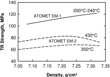
applications especially if taken into consideration at the design step. The transverse rupture strength of ATOMET EM-1 and EM-2 materials after their respective heat treatment is illustrated in Figure 4 as a function of the density. For ATOMET EM-1 iron-resin, cured in the 200°C to 240°C temperature range, the strength increases slightly with an increase of the density and values around 120 MPa are achieved at a density of about 7.30 g/cm³. These values make ATOMET EM-1 one of the highest strength SMC materials in the industry.
Density, g/cm³ 7.05 7.10 7.15 7.20 7.25 7.30 7.35 T R St reng th, M P a 40 60 80 100 120 140 200°C-240°C ATOMET EM-1 ATOMET EM-2 430°C 350°C
Figure 4. Transverse rupture strength of the two SMC materials versus density after a 30-minute heat treatment.
Time, min 0 20 40 60 80 100 120 140 T R St ren g th, MPa 50 60 70 80 90 100 110 350°C 430°C
Figure 5. Effect of the heat treatment time on strength of ATOMET EM-2 treated at 350°C or 450°C.
The ATOMET EM-2 iron-dielectric material has a lower strength and is less dependent on density. Typical values are 60 to 70 MPa after a 30-minute heat treatment at 350°C and 70 to 80 MPa at 430°C. For this material system, an
increase of the heat treatment time has a beneficial effect on the strength. As shown in Figure 5, for parts heat treated at 430°C, an increase of the time at temperature from 30 minutes up to 60 minutes increases the strength from 80 MPa up to 100 MPa. This is coherent with the behaviour observed for the resistivity. Indeed, as the temperature and time increase, properties of the dielectric at the particle interface change: r
decreases and strength increases. F note that for this material system, it i also possible to resin impregnate the p in order to increase further their streng by about 25 MPa [3]. esistivity inally, s arts th . MAGNETIC PROPERTIES 4
he magnetic properties reported in this section were measured at an applied field of 10000 A/m (125
ic in
to n T
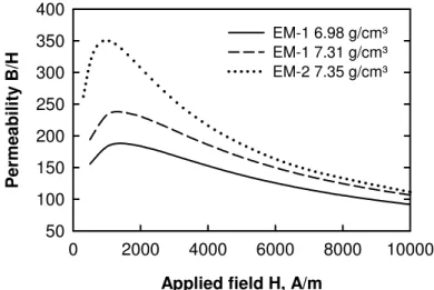
Oe) on rings 5.26 cm OD by 4.34 cm ID by 0.635 cm thick. Rings pressed from ATOMET EM-1 were cured at 200°C and those pressed from ATOMET EM-2 were heat-treated at 430°C. Typical magnetization curves for three different ring samples are given in Figure 6. It is known that magnet induction increases with the density. As illustrated in Figure 6 with the iron-resin material, an increase density from 6.98 g/cm³ up to 7.31 g/cm³ increases the magnetic induction from 1.15 Tesla up to 1.34 Tesla. Now by using the iron-dielectric material system, the magnetic induction is further increased up 1.40 Tesla but more importantly, the shape of the magnetization curve improves. Indeed, the ease of magnetization or permeability, which is given by the slope of the curve, increases. This is illustrated i
Figure 7 where the relative permeability calculated from the magnetization curve of the three ring samples is given as a function of the applied field.
Applied field H, A/m
0 2000 4000 6000 8000 10000 Ma gnet iz a ti on B, T 0.0 0.2 0.4 0.6 0.8 1.0 1.2 1.4 EM-1 6.98 g/cm³ EM-1 7.31 g/cm³ EM-2 7.35 g/cm³
Figure 6. Typical magnetization curves of three different materials: iron-resin EM-1 at
he relative permeability increases rapidly with the applied field and reaches the maximum the
and 6.98 g/cm³ and 7.31 g/cm³ density and iron-dielectric EM-2 at 7.35 g/cm³ density.
T
permeability value at about 1500 A/m before decreasing smoothly with a further increase of applied field. As can be seen, at high applied fields the relative permeability of all materials converges. The maximum permeability values are about 250 for the iron-resin material system around 350 for the iron-dielectric material system. This improvement in magnetization is due to a thinner distributed air gap in the iron-dielectric material (that translates into a lower resistivity) and to a certain extent of stress relief that occurs during the 430°C heat treatment.
Applied field H, A/m
0 2000 4000 6000 8000 10000 Pe rme ab ility B /H 50 100 150 200 250 300 350 400 EM-1 6.98 g/cm³ EM-1 7.31 g/cm³ EM-2 7.35 g/cm³
Figure 7. Relative permeability as a function of the applied field derived from the magnetization curves of the three materials shown in Figure 6.
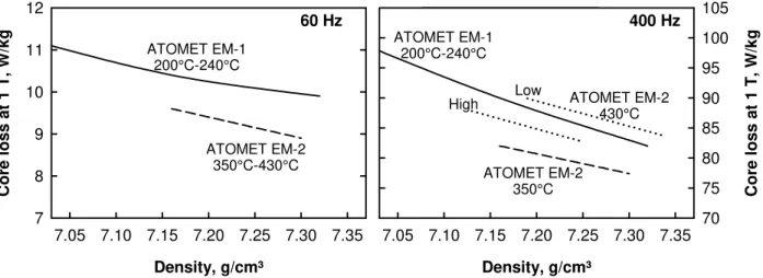
Typical AC losses e 8 for the iron-ials, at 1 Tesla measured at 60 Hz and 400 Hz are presented in Figur
resin and iron-dielectric SMC materials. In both cases AC losses decrease with an increase in density that can be attributed to a decrease in the hysteresis loss. In fact, with powdered mater as the density increases magnetization becomes easier and higher permeability and lower coercive force are obtained. This improvement in DC characteristics with an increase in density translates into a decrease of the hysteresis portion of the core loss.
Density vs 240°C Density vs 240°C Density, g/cm³ 7.05 7.10 7.15 7.20 7.25 7.30 7.35 Co re lo s s a t 1 T , W/ kg 7 8 9 10 11 12 ATOMET EM-1 200°C-240°C ATOMET EM-2 350°C-430°C Density, g/cm³ 7.05 7.10 7.15 7.20 7.25 7.30 7.35 Co re lo s s a t 1 T , W/ kg 70 75 80 85 90 95 100 105 ATOMET EM-1 200°C-240°C ATOMET EM-2 350°C ATOMET EM-2 430°C Low High 60 Hz 400 Hz
Figure 8. Core loss at 1 Tesla as a function of the density for the ATOMET EM-1 and ATOMET
t 60 Hz, the iron-dielectric ATOMET EM-2 material shows losses approximately 10% lower than
.
als. t and
. PROCESSING AND COMPONENT APPLICATION ASPECTS EM-2 materials: measurements at 60 Hz (left) and 400 Hz (right).
A
for ATOMET EM-1: 9.0 W/kg and 10.0 W/kg respectively at a density of 7.30 g/cm³. This is due to the heat treatment (between 350°C and 430°C) that induces some degree of stress relief in the material and consequently decreases the hysteresis loss. At 400 Hz, losses in the iron-dielectric material vary slightly with the heat treatment temperature and amount of dielectric (low or high) Treating at a higher temperature and using less dielectric in the material decreases the resistivity and increases Eddy currents. In the case of the iron-resin material, the resistivity is higher and Eddy currents are low. At high density, losses at 1 T are about 80 W/kg at 400 Hz for all materi Note that core losses are almost proportional to the frequency (10 W/kg up to 80 W/kg by increasing the frequency from 60 Hz up to 400 Hz) indicating that the insulation is efficien Eddy currents low, even in ATOMET EM-2 which has a lower resistivity.
5
.1 Compaction of ATOMET EM-1 5
s already described, the two types of SMC are different in nature. The iron-dielectric material is a
press-n A
ready mix that is processed by conventional compaction. In the case of the iron-resin material, in order to minimize the organic content and maximize the strength, no internal lubricant is used and it is required to lubricate the die walls for the compaction and ejection of the parts. As mentioned previously, the changes that were brought to the powder manufacturing process improved the powder handling at the press: improved flow, increased apparent density and elimination of the dusting. On the compaction side, a
efficient die wall lubrication system was developed and is now commercialized1. This system distributes the lubricant uniformly onto the die walls and in the most intricate areas of the part insuring safe and easy compaction and ejection [4]. Even if conventional lubricants such as zinc stearate or amide wax can be used with this die wall lubrication system, the best results in terms of surface finish, ejection pressures and part complexity have been achieved by using newly developed high performance external lubricants. These are composite lubricants specifically optimized to lubricate die walls and improve both the
stripping and sliding ejection characteristics.
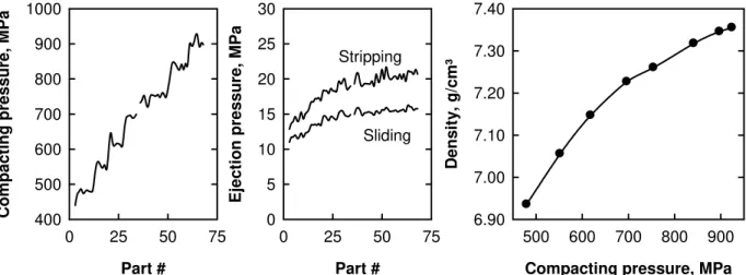
Trials were conducted on a 150-ton mechanical press equipped with the die wall lubrication system. The iron-resin SMC was pressed into 15 teeth gears 50 mm diameter by 16.5 mm thick (tool steel die) and approximately 165 g each using a composite external lubricant. Graphs in Figure 9 show the step-by-step increasing compacting pressure with the corresponding stripping and sliding ejection pressures and the calculated compressibility curve.
Compacting pressure, MPa
500 600 700 800 900 D e ns it y , g /cm ³ 6.90 7.00 7.10 7.20 7.30 7.40 Part # 0 25 50 75 Eject io n p ressu re, MPa 0 5 10 15 20 25 30 Part # 0 25 50 75 Co m p act in g p ressu re , MPa 400 500 600 700 800 900 1000 Sliding Stripping
Figure 9. Increasing step-by-step compacting pressure (left), corresponding stripping and sliding ejection pressures (middle) and compressibility curve (right) for ATOMET EM-1 pressed into 16.5 mm thick gears using a composite lubricant in the die wall lubrication system.
Both stripping and sliding ejection pressures increase with the compacting pressure but in a much lesser extent. In this example, the compacting pressure increases continuously while the
corresponding ejection pressures increase only for a while and reach a plateau quite rapidly: around 20 MPa in stripping pressure and 15 MPa in sliding pressure. The density increases continuously with the compacting pressure and values around 7.35 g/cm³ were achieved in this example at a compacting pressure of 900 MPa (fig. 9 right).
A short production run was also made for 17.8 mm thick rectangular bars 76.2 mm long x 12.7 mm wide (approximately 125 g each) pressed at 615 MPa using the same die wall lubrication system and external composite lubricant. The variation in compacting pressure and stripping and sliding ejection pressures is illustrated in Figure 10.
After a period of warming up (approximately 65 parts), the compacting pressure was stabilized and 225 parts were made without press adjustments at a compacting pressure of 616 MPa with a standard deviation of 7.2 MPa or less than 1.2% in relative standard deviation. The stripping and sliding ejection
1
pressures stabilized around 20 and 15 MPa respectively. These statistics compare favourably to those achieved in conventional compaction of press-ready mixes. At the end of the short run, increasing the compacting pressure up to 760 MPa increased the density from 7.15 g/cm³ up to 7.30 g/cm³. Interestingly, the ejection pressures increased by less than 2 MPa only and the surface finish of the parts remained good. Part # 0 50 100 150 200 250 300 Com p act ing pressure, M P a 200 300 400 500 600 700 800 Eject ion pressure, M P a 0 5 10 15 20 25 30 35 40 Stripping Sliding PCompaction
Figure 10. Variation in compacting pressure and ejection pressures for ATOMET EM-1 pressed into 17.8 mm thick rectangular bars using a composite lubricant in the die wall lubrication system.
5.2 Heat treatment of SMC
The heat treatment purposes and conditions for the two types of SMC are not the same. In the case of the iron-resin material, the object of the heat treatment is to cure the thermoset phenolic resin in the material in order to maximize the mechanical strength. The curing treatment is carried out in air at a temperature between 200°C and 240°C for 30 to 60 minutes. During such a treatment, traces of ammonia,
formaldehyde and phenol may be released from the resin in the SMC. For instance, in laboratory it was determined that the amount of formaldehyde released at 200°C in a closed vessel during a sampling period of two hours was 0.10 ± 0.02 mg per kg of iron-resin parts. These are minute quantities that are easily dealt with by taking the precautions normally used in the heat treatment of any P/M part. For instance, curing the parts in a furnace with an external vent in order to expel the off-gazes outside the building is one procedure.
In the case of the iron-dielectric material, the objects of the heat treatment are to burn-off the lubricating part of the dielectric, to increase the mechanical strength and to partially stress relief the parts. In fact, the treatment is very similar to the delubrication step that takes place in the preheat zone of a sintering furnace. Here again, basic safety precautions must be taken. Indeed, if at low temperature some water vapour may evolve from the material (dehydration of the dielectric), carbon monoxide gas evolves as the temperature increases and the lubricant burns off. Tests were carried out in laboratory to monitor the CO evolution during the heat treatment of ATOMET EM-2. Carbon monoxide readings were taken at the exhaust of a tube furnace heated at 430°C with 375 g of ATOMET EM-2 parts in the furnace and an air flow rate of 2 l/min. The concentration of CO in exhausted air in ppm recorded in these conditions is given in Figure 11 as a function of time. The temperature profile as read in one of the samples is also reported. The carbon monoxide starts to evolve quite early in time and temperature and most of the CO is expelled during the first half of the heat treatment. In the second half of the plateau, the level of CO decreases to values below 20 ppm. Note that these high levels of CO content were obtained in the furnace
and not in the workplace. In a working environment, the permissible exposure limit for an eight-hour period allowed by OSHA is 50 ppm [5].
Time, min 0 20 40 60 80 T e mper at ur e, °C 0 50 100 150 200 250 300 350 400 450 Temperature CO Content CO Cont ent , ppm
Figure 11. Temperature profile in a sample of ATOMET EM-2 and CO content read at the exit of a tubular furnace at 430°C as a function of time (375 g of parts, air flow of 2 l/min).
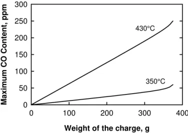
The content of CO in the exhausted air is also dependent on the quantity of parts in the furnace, the maximum temperature of the heat treatment and the air flow rate. Similarly to the preceding test, carbon monoxide readings were taken at the exhaust of a tube furnace heated at 350°C or 430°C with different quantities of ATOMET EM-2 parts in the furnace and an air flow rate of 2 l/min. The mean maximum value of CO content in air is reported in Figure 12 as a function of the weight of the charge. It is seen that the CO content increases with the quantity of parts and when they are heat treated at a lower temperature, e.g., 350°C rather than 450°C, the dielectric burns less (this leaves more insulation and higher resistivity) and there is much less evolution of CO. It has been observed also that if the air flow is reduced, the concentration in CO increases and this may affect the quality of the parts. Best results are obtained when the CO content in the second half of the plateau of the heat treatment is kept low. It is thus important that the gazes be either burned off or properly vented.
Weight of the charge, g
0 100 200 300 400 M axi m u m CO Cont ent , ppm 0 50 100 150 200 250 300 350°C 430°C
Figure 12. Maximum CO content read at the exit of a tubular furnace at 350°C or 430°C as a function of the weight of ATOMET EM-2 parts.
5.3 Effect of temperature on strength of SMC
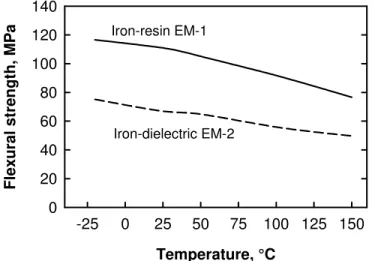
SMC being intended for use in machines that operate typically at ambient up to 150°C, their
flexural strength was measured in the -25°C to 150°C temperature range. A series of 12.7 mm thick rectangular bars (76.2 mm long x 12.7 mm wide) were pressed at 7.00 g/cm³ from ATOMET EM-1 and at 7.15 g/cm³ from ATOMET EM-2. The iron-resin parts were cured at 200°C for 30 minutes and the iron-dielectric parts heat treated at 430°C for 30 minutes. The bars and transverse rupture test fixtures were installed in a cooling-heating chamber with a hole in top and bottom through which the fixtures were connected to an instrumented compression testing machine. After a 10-minute stabilization period, the bars were broken at temperature (5 bars per temperature). As shown in Figure 13, the strength decreases continuously with an increase of the temperature with a remaining strength of about 70% at 150°C compared to room temperature. The iron-resin is still the highest strength material at high temperature: slightly over 75 MPa at 150°C.
Temperature, °C -25 0 25 50 75 100 125 150 Fl exur a l s tr e ngt h, M P a 0 20 40 60 80 100 120 140 Iron-resin EM-1 Iron-dielectric EM-2
Figure 13. Effect of temperature on the flexural strength of the iron-resin and iron-dielectric SMC materials.
5.4 Fatigue properties of ATOMET EM-1
In the design of electrical machines, besides the electrical and magnetic properties there are also the mechanical considerations. It is common to report the strength of SMC as determined by testing three-point bending specimens under monotonic loading, but in some cases and for certain applications, fatigue data may be required as well. Tests were thus carried out in order to determine the axial fatigue strength of the ATOMET EM-1 material.
Two types of flat test bars were used for these tests. The tensile strength was determined from bars 89.6 mm long by 8.7 mm wide by 6.4 mm thick with a central straight gage area 25.4 mm long by 5.7 mm wide. Specimens were pressed to 7.20 g/cm³ and cured at 200°C for 30 minutes in air. For the fatigue testing, bars 90 mm long by 10 mm wide by 7.2 mm thick with a central curved gage area 25.4 mm long and 5.7 mm wide in the centre were used. The iron-resin powder was pressed at a density of 7.00 and 7.20 g/cm³ and the specimens cured at 200°C for 30 minutes in air. For both tensile and fatigue specimens, the edges of the gage area were chamfered after curing in order to reduce possible stress concentrations.
an applied loading speed of 2.5 mm/min according to the MPIF Standard 10. For the fatigue tests, the specimens were subjected to a uniaxial tension-compression loading mode (R = -1) using a hydraulic testing machine at a frequency of 100 Hz. The staircase method was used to analyze the data and determine statistically the mean endurance limit or alternating stress amplitude
σA
for which 50% of test bars would survive 107 cycles. A step of 1.38 MPa (200 psi) was applied with the staircase method. The tensile strengthσT
and mean endurance limitσA
for which 50% of test bars survived 107 cycles are given in Table II for the specimens pressed to 7.00 and/or 7.20 g/cm³.Table II. Tensile strength and fatigue endurance limit of ATOMET EM-1 pressed to 7.00 and/or 7.20 g/cm³ (cured at 200°C/30 min).
Density 7.00 g/cm³ 7.20 g/cm³
Tensile strength
σ
T, MPa --- 57.1 ± 5.8Endurance limit
σA
, MPa 30.0 ± 0.5 33.6 ± 4.2The tensile strength of the iron-resin material at a density of 7.20 g/cm³ is about half of the flexural strength (approximately 115 MPa). This is typical of what is observed for P/M materials. The fatigue endurance limit (50% survival) increases with the density and is about 60% of the tensile strength at 7.20 g/cm³. These results in axial fatigue testing are coherent and in agreement with published results obtained in flexural fatigue testing [6]. In this latter case, their flexural fatigue limit values are approximately twice than those obtained here in axial testing which correspond to the normal tensile-to-flexural strength ratio.
6. CONCLUSIONS
SMC are engineered materials intended to be used in electromagnetic devices in competition with laminated steels. Two types of SMC materials have been described with their properties. The iron-resin ATOMET EM-1 is a high strength and high resistivity material that requires lubrication of the die walls for compaction while the iron-dielectric ATOMET EM-2 is a press-ready mix with improved magnetic properties.
For the ATOMET EM-1 material, changes were brought in the powder manufacturing that improved the flow, increased the apparent density and eliminated the dusting without affecting the mechanical and magnetic properties. In parallel, high performance external lubricants were also developed for the
lubrication of the die walls. With all these improvements, it is now possible to press ATOMET EM-1 into SMC parts with a good surface finish at densities up to 7.30 g/cm³. Moreover, this iron-resin material is amongst the highest strength SMC in the industry with values in the range of 100 to 120 MPa in flexural strength. A tensile strength in the 50 to 57 MPa range and axial fatigue endurance limit in the 30 to 34 MPa range were determined.
Compared to ATOMET EM-1, the ATOMET EM-2 material exhibits slightly better magnetic properties. For example, a maximum permeability around 350 (250 for EM-1) and 10% lower losses at 60 Hz and 1 Tesla (9 W/kg versus 10 W/kg for EM-1). The strength of ATOMET EM-2 is not as high (TRS in the range of 60 to 80 MPa) and for both materials, an increase of the temperature (in service) from room to 150°C decreases their strength by about 30%.
Finally, regarding the processing of the two types of SMC parts, even if they are not sintered, it has been shown that usual safety precautions during the low temperature heat treatments are still required (proper venting).
7. REFERENCES
1. C. Gélinas, F. Chagnon & S. Pelletier, "Development of an Iron-Resin Composite Material for Soft Magnetic Applications", Advances in Powder Metallurgy & Particulate Materials - 1996, MPIF Princeton, NJ, pp 20-85 to 20-97.
2. L.P. Lefebvre & C. Gélinas, "Effect of Material Insulation and Part Geometry on the AC Magnetic Performances of P/M Soft Magnetic Composites", Advances in Powder Metallurgy & Particulate Materials - 2001, Vol. 7, MPIF Princeton, NJ, pp 36-50.
3. L.P. Lefebvre, S. Pelletier & C. Gélinas, "Lubricated iron powders for low frequency soft magnetic applications", Advances in Powder Metallurgy & Particulate Materials - 1999, MPIF Princeton, NJ, Vol. 3, pp 8-11 to 14-97.
4. P. Lemieux, L. Azzi, Y. Thomas, S. Pelletier, P.E. Mongeon & S. St-Laurent, “Pressing challenging parts on a production scale by using die wall lubrication technology”, Paper presented at PM2TEC Montreal, 2005. To be published in Conference Proceedings.
5. US Department of Labor, Occupational Safety and Health Administration (OSHA), Table Z-1 Limits for Air Contaminants - Carbon monoxide.
6. M.J. Dougan, Y. Torres, A. Mateo & L. Llanes, “The fatigue behaviour of soft magnetic composite powders”, Euro PM2004 Conference Proceedings, PM Functional Materials, Vol. 4, pp 637-643.