Publisher’s version / Version de l'éditeur:
Vous avez des questions? Nous pouvons vous aider. Pour communiquer directement avec un auteur, consultez la
première page de la revue dans laquelle son article a été publié afin de trouver ses coordonnées. Si vous n’arrivez pas à les repérer, communiquez avec nous à [email protected].
Questions? Contact the NRC Publications Archive team at
[email protected]. If you wish to email the authors directly, please see the first page of the publication for their contact information.
https://publications-cnrc.canada.ca/fra/droits
L’accès à ce site Web et l’utilisation de son contenu sont assujettis aux conditions présentées dans le site LISEZ CES CONDITIONS ATTENTIVEMENT AVANT D’UTILISER CE SITE WEB.
Research Report (National Research Council of Canada. Institute for Research in
Construction), 2011-09-28
READ THESE TERMS AND CONDITIONS CAREFULLY BEFORE USING THIS WEBSITE.
https://nrc-publications.canada.ca/eng/copyright
NRC Publications Archive Record / Notice des Archives des publications du CNRC :
https://nrc-publications.canada.ca/eng/view/object/?id=ce6ed305-40a5-4271-a21d-61f24f1b9e55 https://publications-cnrc.canada.ca/fra/voir/objet/?id=ce6ed305-40a5-4271-a21d-61f24f1b9e55
NRC Publications Archive
Archives des publications du CNRC
For the publisher’s version, please access the DOI link below./ Pour consulter la version de l’éditeur, utilisez le lien DOI ci-dessous.
https://doi.org/10.4224/20374365
Access and use of this website and the material on it are subject to the Terms and Conditions set forth at
A Testing Method for Seismic Resistance Assessment of Fire-Damaged
Structures
A Testing Method for
Seismic Resistance
Assessment of
Fire-Damaged Structures
Research Report No. RR-318
Date of Issue: Sep 28, 2011
Author: Hossein Mostafaei
2
ACKNOWLEDGEMENTS
The authors would like to thank Mr. Patrice Leroux and Mr. Pier-Simon Lafrance for their assistance and contribution in the implementation of the hybrid tests.
3
A Testing Method for Seismic Resistance Assessment of Fire-Damaged Structures by
Hossein Mostafaei
ABSTRACT
A method for lateral load resistance evaluation of structures that experienced damaged during a fire was developed. The method was implemented for a performance evaluation of a 6-storey reinforced concrete building subjected to lateral displacement, after fire damage. The fire damage was imposed by a 4-hour fire to the beams’ ceiling and a column in a compartment on the first floor of the building. Using a hybrid fire testing method first the whole building was tested in fire and 6 days later, after the entire structure had cooled down to the ambient temperature, the building was subjected to lateral loads determined based on a design seismic load. The lateral load was
distributed vertically and applied on the building by means of a pushover loading. The fire-damaged column was tested experimentally and the two fire-damaged beams and the rest of the building were simulated numerically using SAFIR. The results of the column test were compared with the results of the lateral load response of the column prior to the fire damage. This study shows that the proposed method is a practical cost-effective and reasonably accurate method for assessing seismic resistance of structures after a fire. The test results showed a reduction of both stiffness and seismic resistance capacity of the fire-damaged building.
4
A Testing Method for Seismic Resistance Assessment of Fire-Damaged Structures by
Hossein Mostafaei
INTRODUCTION
A review on the statistics reports and studies show that the average annual fire occurrence in moderate and high-rise buildings exceeds 10,000 incidents only in the United States (Hall, 2001). In Canada more than 50,000 fire incidents were reported annually CCFMFC (2002). About 3500 of these fire incidents occurred in apartments, hotels and dormitories, which could be considered as moderate to high-rise structures. In most of these fire incidents, building structures have experienced minor to major damage due to fire exposure, such as degradation of material properties due to elevated temperatures and damage to structural elements due to thermal expansion.
After a building fire incident, an inspection is required for the assessment of the structural loss and damage and evaluation of the building residual capacity (CIB W14, 1990). One of the main objectives for a post-fire assessment should include long-term effects of the fire damage on the structural performance, such as on the lateral
load/seismic resistance of the structures. Studies have been carried out on seismic resistance of fire-damaged concrete columns using numerical modeling (Mostafaei et al. 2009). However, few experimental methods have been developed and implemented for assessing the residual seismic capacity of structures after fire.
Previously, a hybrid testing (HFT) method was developed for assessing fire performance of whole structures, (Mostafaei, 2010 and Mostafaei, 2011). The method was based on a sub-structuring concept, dividing the structure into two substructures. The two substructures in the HFT method were a test specimen separated from the building, and the rest of the building, being computer simulated. The same methodology has been enhanced for the seismic performance evaluation of fire-damaged buildings.
The method presented in this report was implemented using a one column furnace facility for performance assessment of the whole building subjected to fire and then to a seismic lateral load. Therefore, the test costs would be reasonably lower than testing the specimen in two different facilities or testing the whole building for the fire and earthquake loadings. On the other hand, using the hybrid method, performance of the entire structures is included in the seismic and fire resistance evaluation. Hence, this method is expected to be more accurate than evaluating individual elements of the building separately.
This report includes descriptions of the seismic performance evaluation method developed through this study, details of a 6-storey building prototype and results of the lateral load/displacement response assessment of the 6-storey building after a 4-hour fire exposure.
5
Other loads, such as winds, impact and explosion also cause lateral loads and forces on the buildings. Hence, a similar technique or methodology could be developed for performance evaluations of fire-damaged structures subjected to these lateral loads.
THE 6-STOREY BUILDING SPECIMEN
A 6-storey reinforced concrete building specimen was designed based on the Canadian Seismic Code and Concrete Design Standard for the seismic resistance testing. Further details of the design were described in the HFT Methodology report (Mostafaei 2011). Figure 1 shows the overall 3D structural frame configuration of the building.
FIGURE 1. The 6-Storey Reinforced Concrete Building Structure Specimen.
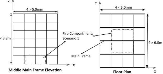
Figure 2 shows both the floor plan of the building and the elevation of the main frame as well as the location of the fire compartment for the fire test. The main frames of the building are in the direction with the shorter spans (5.0 m), as shown in Figure 2. The frames perpendicular to the main frames are considered secondary frames. The floor loads are considered to be carried only by the main frames.
FIGURE 2. The Elevation and Floor Plan of the 6-Storey Reinforced Concrete Building.
The seismic weight of the building was determined considering a commercial building located in Ottawa, based on the Canadian National Building Code. As for the results, total seismic weight of the roof was W6= 2544kN and that for the 1st to 5th floors
4 × 5.0mm 4 × 6.0m Main Frame Floor Plan X X Z Y 6 × 3.8m Fire Compartment: Scenario 1
Middle Main Frame Elevation
6
were, W1= W2= W3= W4= W5= 4104 kN, respectively. Lateral load distribution of the
building can be determined by Equation (1).
��= (� − ��)∑����ℎ��ℎ�
�=1 (1)
where, w is the weight of each floor; h is height of each floor from the foundation level of the building. V is the total lateral seismic load and Ft is the portion of V to be applied at
the roof level. In this study, since the natural period of the building is larger than 0.7s, based on the employed seismic code, Ft=0.
For any V, based on the building elevations provided in Figure 2 and the calculated weights, ∑��ℎ�
��ℎ� �
�=1 can be determined.
The vertical load applied on the main mid frames at roof level was 33 kN/m and that at other levels was 53 kN/m. The end frames were subjected to half of the above loads accordingly.
Columns section
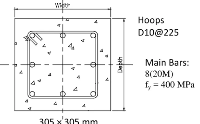
The cross section and details of the reinforcements for both column specimens, as well as the rest of columns in the 6-storey building specimen are shown in Figure 3. Concrete compressive strength, for both column specimens, were 96 MPa based on three cylinder compression tests carried out before the fire test. The concrete was made of siliceous aggregates with a mix of steel fibre, 42 kg per cubic meter. Both longitudinal and transverse bars had yield strength of 400 MPa. Figure 4 shows dimensions of the columns and their reinforcement.
Beam sections
The same concrete properties were considered for beams as that for the columns. Figure 5 shows the cross section for the beams of the main frames with material properties for concrete and steel. Figure 6 illustrates the cross section for beams in the secondary frames. In order to include contribution of the floor slabs in the building response, all beams were designed as T beams. For simplicity, end beams were modeled with the same cross sections as that of the mid beams (balcony type).
FIGURE 3. Cross Section of Columns at all Levels.
Hoops D10@225 Main Bars: 8(20M) fy = 400 MPa 305 × 305 mm
7
FIGURE 4. Reinforcement and Details of the Column Specimen.
FIGURE 5. Cross Section of Beams in the Main Frames.
FIGURE 6. Cross Section of Beams in the Secondary Frames.
Hoops D10@200 Main Bars: 4(25M) fy = 400 MPa 150 mm 500 mm 300 mm 500 mm 50 mm Hoops D10@200 Main Bars: 4(15M) fy = 400 MPa 150 mm 250 mm 200 mm 600 mm 50 mm
8
COLUMN TEST FACILITY
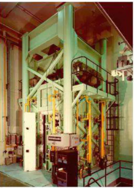
The tests were carried out using the NRC’s full-scale column furnace facility in Ottawa. The furnace is capable of applying axial loads up to 9790 kN (2200 kips), lateral loads up to 110 kN (25 kips) in North-South direction, lateral loads up to 310 kN (70 kips) in East-West direction with/without fire loads. Further details are provided by Lie, T.T. (1980).
During the test, the axial load was controlled by servocontrollers and measured with pressure transducers with ~4.0 kN accuracy at lower load levels and relatively better at higher loads. Lateral loads are controlled and measured with load cells.
Lateral and axial displacements are measured using transducers with an accuracy of ~0.002 mm.
The furnace chamber has a floor area of 2642 x 2642 mm and height of
3200 mm. The axial loading and lateral loading could be applied to the column specimen during the fire or before and after, without the fire. Therefore, using this facility both for the fire test and post-fire seismic test can be implemented as described in this report.
Figure 7 shows the column furnace chamber.
FIGURE 7. NRC’s Column Furnace Facility.
FIRE TEST TO IMPOSE FIRE DAMAGE
For the fire test of the building, a hybrid fire testing (HFT) approach was
employed. Figure 8 illustrates the HFT implemented for the 6-storey building specimen. The column specimen, which was tested in the furnace, was the centre column on the first floor of the building, in the centre of the fire compartment. The rest of the building structure, including beams and the floor in the fire compartment, were simulated using
9
the SAFIR software (the new version, which was released in 2011).The average temperatures in the fire compartment, both in the furnace and in the simulation during the test, were controlled based on the CAN/ULC-S101 standard temperature-time curve. Summary of the fire test result is provided in this report.
FIGURE 8. The HFT Implementation for the 6-Storey Reinforced Concrete Building Specimen.
Results of the Fire Test
Results of the fire test, including temperature distribution on the cross sections, load and deformation response of the columns, and description of the HFT methodology were provided in details in two research reports previously published by Mostafaei et al. (2011) and Mostafaei (2011).
LATERAL/SEISMIC RESISTANCE TEST
Support Conditions
For the column specimen, no rotation or lateral displacement was imposed at the top and bottom of the specimen. For the rest of the building, at the point where the column specimen was separated to the frame, no rotation was permitted. However, the frame was free to displace in the two horizontal directions.
Lateral/Seismic Resistance Test before fire Exposure
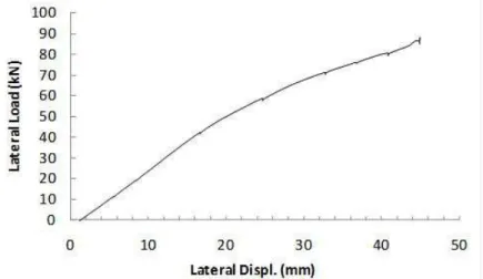
Prior to the fire test, the column specimen was tested laterally under a constant load to determine its initial lateral stiffness and load-displacement response. Initially the column was subjected to an axial load 1000kN. Then, lateral load was applied on the column specimen using a displacement-controlled loading method. Figure 9 shows the results of the load-lateral displacement response of the column.
Lateral loading was stopped before any shear cracks appeared on the column. That was to avoid any damage to the column specimen for the fire test. However, using an analytical method, referred to as axial-shear-flexure interaction (ASFI) (Mostafaei and Hum, 2010), first the modeling was validated for the available test results and then the full response was estimated. Figure 10 shows both validation and the full lateral
10
response estimation for the column. It indicates a maximum lateral load capacity of 95kN for the column specimen under 1000kN axial load, before any fire damage.
FIGURE 9. Lateral Load Response of the Column Specimen before Fire Test.
FIGURE 10. Lateral Load Response of the Column Specimen before Fire: Test and Analysis.
Lateral/Seismic Resistance Test after Fire Exposure
Hybrid Testing Application
A similar load and deformation interaction process to that of the HFT (Mostafaei 2010), was employed for the seismic test, but without fire exposure. The equivalent static seismic loading was applied on the building by means of displacement control loading/pushover loading. To do so, equation (1) was employed to obtained vertical distribution of the equivalent seismic load V at different floor levels of the whole building. Then, a numerical analysis was employed for the building under the applied vertical load and this distributed the lateral loads when V increased from 0 to when lateral
displacement on the 1st floor level of the building reached about 50mm, that was the lateral displacement capacity of the column furnace at that time. Modification is currently
11
being done to enhance this limit. From this analysis, lateral displacement at different floor levels were obtained for the building at different seismic/lateral loads. During the hybrid seismic test, the building was subjected to this lateral displacement distribution, which simulated the seismic loading.
The seismic hybrid test was implemented for the 6-storey building subjected to the above lateral displacements. The test included controlling the axial load of the column specimen based on the axial load calculated from the analysis of the rest of the building and controlling the lateral load of the building, at the joint where the column specimen was separated, by the lateral load response of the column specimen during the test.
Test Results
The seismic resistance assessment was employed using the hybrid testing, six days after the fire test. Initially, due to considerable shortening during the fire and the cooling phase, the column specimen carried almost no load, set to 171kN. This is mainly for the case when the building frame is strong enough and would not deflect down with the column and therefore carry the load of the shorter column. However, for a weaker frame, the column could be subjected to its initial axial load, since the frame will deflect with the column. As well, in the long term, the creeps in the concrete frame could compensate for the column shortening and again the column would carry much higher load. To consider a worst case scenario, the initial axial load, 2000kN, was applied during the hybrid seismic test. However, before reaching this axial load, the column was tested laterally, up to 50mm lateral displacement, under lower axial loads for the purpose of comparison.
Comparing lateral response before and after fire
The column specimen was under an axial load of 171kN before the lateral loading test started. In order to compare the residual seismic/lateral response of the column before and after the fire, the column axial load was increased to 1000kN, since the results for this axial load was available for the column before fire damage. Then lateral load was employed to the column specimen using a displacement contorted loading.
FIGURE 11. Lateral Load Response of the Column Specimen before and after Fire Test.
12
Figure 11 shows the results of load-displacement response of the column specimen before and after the fire exposure. That is about a 31% reduction in stiffness after the 4 hour fire exposure, which could affect the natural period of the structure. However, the column did not fail under the applied maximum lateral deformation, 1.1%.
Seismic/Lateral load capacity
To determine seismic/lateral load capacity of the column, the axial load was set to 2000kN, that is the full axial load initially carried by the column. Then, using the hybrid method, lateral displacements were imposed to the building at different levels. As lateral displacement increased, axial load started to fall, obtained from the analysis. Lateral loading was increased until the building reached about 1.1% lateral displacement ratio, which was the current lateral displacement limit for the facility.
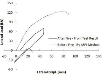
In order to achieve the column failure, the axial load was increased for the next cycle to 2350kN. The column failed at this axial load and under a lateral load of 6kN and lateral displacement of 6mm. Since this is a very small lateral displacement, it could be concluded that the column failed, in fact, under the axial load. The result indicates that the column lost more than 70% of its axial load capacity due to the fire damage. Furthermore, this indicates that the lateral displacement ratio of 1.1% and the lateral load of 70kN, achieved in the previous cycle, could be considered as the column’s lateral deformation and load capacity. An analysis was carried out again for the column
specimen before any fire damage, using the ASFI method, but with axial load of 2000kN. Figure 12 illustrates the lateral response of the column specimen before the fire,
estimated by ASFI method and after the fire, obtained from the test. The results
indicated a 50% reduction in the column’s maximum lateral deformation capacity and a 30% reduction in its lateral load capacity after fire damage.
FIGURE 12. Lateral Load Response of the Column Specimen after Fire Test until failure; before and after Fire.
Figure 13 illustrates the axial and lateral load response of the column for two cycles; cycle 1 started with an axial load of 2000kN and cycle 2 with an axial load of 2350kN. The figure shows that the axial load of the column was decreased from 2000kN at about a zero lateral load to 1750kN at 69kN lateral load in three steps, which indicates the effects from the interaction of the column specimen with the rest of the building, being simulated by computer. That was because the frame had no fire damage and had
13
its full stiffness. Increasing the lateral load resulted in lifting up the columns of the
building, due to their axial-flexure mechanism. However, the column specimen damaged in fire had much less stiffness and could not follow the rest of the columns; therefore its axial load was reduced as the lateral displacement was raised.
FIGURE 13. Axial Load vs Lateral Load Response of the Column Specimen after Fire Test until failure.
Figure 14 shows the same results but for axial displacement. It indicates that at the column failure, it has experienced about 39 mm axial deformation, during both fire and seismic tests, indicating a column shortening of about 1% of its height. That is about 400% more than axial deformation failure of a column with no fire damage, which is 0.25%. However, on the day of the seismic test, the axial load was increased from zero to 2350kN, failure, and the corresponding relative axial deformation was 12 mm. That is about 0.3% strain of concrete at its maximum capacity, which seems to be reasonable and very close to that of the concrete with no fire damage. Therefore, since the reduction in the axial load capacity was 70%, the same reduction could be considered for the axial stiffness.
FIGURE 14. Axial Displacement vs Lateral Load Response of the Column Specimen after Fire Test until failure.
14
Figure 15 shows the column specimen before and after the fire hybrid testing. Figure 16 illustrate the same columns specimen, 6 days later, before and after the seismic test.
FIGURE 15. Column Specimen before, on the Left, and just after the Fire Test, on the Right.
FIGURE 16. Column Specimen Six Days after the Fire Test, on the Left, before the Seismic Test, and on the Right, after the Seismic Test.
Lateral Displacement Response of the Whole Building
The numerical simulation of the whole building, except for the column specimen which was tested, was carried out using a computer software called SAFIR (2005),
15
during the hybrid test. Figure 13 shows that the axial load was changed three times during the load cycle shown. This means the analysis was carried out at least three times during this cycle. For a smoother response, more analyses can be implemented during each cycle.
Although all the performance components for the building structure were calculated during the test, this study focuses more on the application of the hybrid seismic test of fire-damaged buildings. Therefore, only overall results of the structural performance of the building are provided in this report. Figure 17 illustrates deformation of the building at the time when the lateral displacement at the top of the column
reached its maximum value, shown in Figure 12. The building experienced 217 mm lateral displacement at the roof level, which is about 1.1% drift ratio.
FIGURE 17.Lateral Displacement Response of the 6-Storey Building corresponding to the time that the Column Specimen Experienced its maximum
Lateral Displacement, Figure 12.
CONCLUSION
A hybrid equivalent seismic testing was implemented successfully for
performance evaluation of a 6-storey reinforced concrete building 6 days after it was damaged by a 4 hour fire in a compartment in the centre part of the building’s main floor. The following conclusions can be made based on the results of this study.
1. Lateral load-deformation stiffness of the column damaged by a 4-hour fire exposure reduced by 31%. This was obtained under an axial load of 1000kN, which is about 42% of its axial load capacity after the fire damage.
2. Fire damage caused a 50% reduction in the column’s maximum lateral deformation capacity and a 30% reduction in its lateral load capacity.
3. The concrete column lost about 70% of its initial axial stiffness, as well as, its axial load capacity, due to the 4-hour fire damage. The compression peak strain of fire-damaged concrete was 0.3%, which was similar to that of a concrete without fire damage.
16
4. The column damaged by fire experienced a 39 mm axial deformation, column shortening, which is about 1% of its height, at its failure. This is about 400% more than axial deformation failure of a column with no fire damage, which is 0.2%. This would be due to the effects of concrete transient strain in fire.
5. At the maximum lateral displacement capacity of the column specimen, the building experienced a 217 mm lateral displacement at roof level.
This study was carried out, as an example, for a 6-storey building structure which was made of high strength concrete mixed with steel fibre, due to the availability of such a column specimen. However, the same method would need to be employed to
investigate effects of fire damages on the seismic response and load capacities, for other structural materials, e.g. normal strength concrete, steel, wood, etc.
REFERENCES
1. Mostafaei, H. (2011). “Hybrid Fire Testing for Performance Evaluation of Structures in Fire - Part 1 Methodology,” Research Report No. 316, National Research
Council Canada, pp.1-20.
2. Mostafaei, H., Leroux, P., Lafrance, P.S. (2011). “Hybrid Fire Testing for Performance Evaluation of Structures in Fire - Part 1 Application,” Research Report No. in press, National Research Council Canada,pp.1-34.
3. Mostafaei, H. and Hum J.K. (2010). “Response Simulation of Reinforced Concrete Columns under Lateral Loads,” NRC Research Report 294, pp. 55.
4. Mostafaei, H. (2010). “NRC-IRC develops new approach for structural fire resistance”, Construction Innovation, Vol. 15, Issue 1, ( http://www.nrc-cnrc.gc.ca/eng/ibp/irc/ci/v15no1/8.html ).
5. SAFIR, (2001). A Thermal/Structural Program Modelling Structures under Fire, Franssen J.-M., Engineering Journal, A.I.S.C., Vol. 42, No. 3, pp. 143-158, http://hdl.handle.net/2268/2928.
6. Lie, T.T. 1980. “New facility to determine fire resistance of columns,” Canadian Journal of Civil Engineering, Vol. 7, No. 3, pp. 551-558.
7. CAN/ULC-S101, “Fire Endurance Tests of Building Construction and Materials”, Underwriters’ Laboratories of Canada, Scarborough, ON.
8. Hall, J.R. (2001). “High-rise building fires.” NFPA, Quincy, MA.
9. CCFMFC (2002). “Fire Losses in Canada”, Annual Report 2002, Council of Canadian Fire Marshals and Fire Commissioners, pp. 42.
10. CIB W14. (1990). “Repairability of fire damaged structures.” CIB W14 Report, edited by U Schneider, Fire Safety Journal, Special Issue, 16(4), 251-336. 11. Mostafaei, H., Vecchio, F.J., Benichou, N. (2009). “Seismic resistance of
fire-damaged reinforced concrete columns,” Conference on Improving the Seismic Performance of Existing Buildings and other Structures, by the Applied Technology Council and the Structural Engineering Institute of ASCE, San Francisco,