Publisher’s version / Version de l'éditeur:
Journal of Engineering for Gas Turbines and Power, 132, 2, pp.
022801-1-022801-10, 2010-02-01
READ THESE TERMS AND CONDITIONS CAREFULLY BEFORE USING THIS WEBSITE. https://nrc-publications.canada.ca/eng/copyright
Vous avez des questions? Nous pouvons vous aider. Pour communiquer directement avec un auteur, consultez la première page de la revue dans laquelle son article a été publié afin de trouver ses coordonnées. Si vous n’arrivez pas à les repérer, communiquez avec nous à [email protected].
Questions? Contact the NRC Publications Archive team at
[email protected]. If you wish to email the authors directly, please see the first page of the publication for their contact information.
NRC Publications Archive
Archives des publications du CNRC
This publication could be one of several versions: author’s original, accepted manuscript or the publisher’s version. / La version de cette publication peut être l’une des suivantes : la version prépublication de l’auteur, la version acceptée du manuscrit ou la version de l’éditeur.
For the publisher’s version, please access the DOI link below./ Pour consulter la version de l’éditeur, utilisez le lien DOI ci-dessous.
https://doi.org/10.1115/1.3124667
Access and use of this website and the material on it are subject to the Terms and Conditions set forth at
An experimental and modeling study of HCCl combustion using
n-heptane
Guo, Hongsheng; Neill, W. Stuart; Chippior, Wally; Li, Hailin; Taylor, Joshua
D.
https://publications-cnrc.canada.ca/fra/droits
L’accès à ce site Web et l’utilisation de son contenu sont assujettis aux conditions présentées dans le site LISEZ CES CONDITIONS ATTENTIVEMENT AVANT D’UTILISER CE SITE WEB.
NRC Publications Record / Notice d'Archives des publications de CNRC:
https://nrc-publications.canada.ca/eng/view/object/?id=cf6db9d6-bca5-4cf6-af9b-a2f197d893e1
https://publications-cnrc.canada.ca/fra/voir/objet/?id=cf6db9d6-bca5-4cf6-af9b-a2f197d893e1
Hongsheng Guo
W. Stuart Neill
Wally Chippior
National Research Council Canada, 1200 Montreal Road, Ottawa, ON, K1A 0R6, Canada
Hailin Li
West Virginia University, P.O. Box 6106, Morgantown, WV, 26506
Joshua D. Taylor
National Renewable Energy Laboratory, 1617 Cole Boulevard, Golden, CO 80401
An Experimental and Modeling
Study of HCCI Combustion Using
n-Heptane
Homogeneous charge compression ignition (HCCI) is an advanced low-temperature combustion technology being considered for internal combustion engines due to its po-tential for high fuel conversion efficiency and extremely low emissions of particulate matter and oxides of nitrogen 共NOx兲. In its simplest form, HCCI combustion involves the
auto-ignition of a homogeneous mixture of fuel, air, and diluents at low to moderate temperatures and high pressure. Previous research has indicated that fuel chemistry has a strong impact on HCCI combustion. This paper reports the preliminary results of an experimental and modeling study of HCCI combustion using n-heptane, a volatile hydro-carbon with well known fuel chemistry. A Co-operative Fuel Research (CFR) engine was modified by the addition of a port fuel injection system to produce a homogeneous fuel-air mixture in the intake manifold, which contributed to a stable and repeatable HCCI combustion process. Detailed experiments were performed to explore the effects of critical engine parameters such as intake temperature, compression ratio, air/fuel ratio, engine speed, turbocharging, and intake mixture throttling on HCCI combustion. The influence of these parameters on the phasing of the low-temperature reaction, main combustion stage, and negative temperature coefficient delay period are presented and discussed. A single-zone numerical simulation with detailed fuel chemistry was developed and validated. The simulations show good agreement with the experimental data and capture important combustion phase trends as engine parameters are varied.
关DOI: 10.1115/1.3124667兴
1 Introduction
Homogeneous charge compression ignition 共HCCI兲 is an ad-vanced low-temperature combustion technology. In principle, HCCI involves the auto-ignition of a homogeneous mixture of fuel, air, and diluents at low to moderate temperatures and high pressure. This approach enables the engine designer to have a high compression ratio 共CR兲, minimize air throttling losses, and rapidly burn the fuel-air mixture near top dead center, which contributes to high thermal efficiency. Meanwhile, the burning of a homoge-neous fuel-lean mixture at relatively low-temperature suppresses the formation of particulate matter 共PM兲 and oxides of nitrogen 共NOx兲, the two problematic emissions from diesel engines. These desirable combustion characteristics make HCCI a potentially promising combustion mode for internal combustion engines 关1,2兴.
HCCI was identified as a distinct combustion phenomenon in the late 1970s. Early research 关3–5兴 investigated the potential ben-efits of HCCI combustion and recognized its potentially attractive characteristics for internal combustion engines. Different ap-proaches for controlling HCCI combustion phasing have been re-ported 关1,5–7兴. Christensen et al. 关8兴 demonstrated that HCCI combustion has a multifuel capability compared to traditional in-ternal combustion engines. Recent experimental data available in the open literature 关8–12兴 indicate that fuel chemistry has a strong impact on HCCI combustion. It has been recognized that there is a potential benefit to better understand the fundamentals of HCCI combustion, and, in particular, tailoring a fuel specifically for HCCI combustion 关9兴. HCCI combustion of both gasoline- and
diesel-like fuels and their mixtures has been investigated 关10–12兴. In these studies, direct injection 共DI兲 diesel engines were adopted due to the increasing interest in employing low-temperature com-bustion strategies for the reduction in diesel engine emissions 关11兴. A low-pressure port fuel injector was used in one study to atomize diesel fuels for HCCI combustion research 关12兴.
Apart from fuel chemistry, the fuel injection system and the physical properties of the fuel affect the formation of a homoge-neous fuel-air mixture and the HCCI combustion process 关11,13兴. The experimental results from prototype production engines, typi-cally employing direct injection strategies, reflect the combined effects of fuel injection, fuel-air mixing, and fuel chemistry. The results obtained by different manufacturers may not be consistent due to different fuel injection hardware and combustion strategies adopted to form the homogeneous mixture and control HCCI combustion. This makes it very difficult to ascertain the fuel chemistry effects. In addition, it is very difficult to interpret some experimental data available in the open literature without detailed knowledge of the specific engine hardware and the low-temperature combustion strategy employed. However, detailed in-formation is not always provided, particularly when economic considerations are paramount. Thus, there appears to be a need to develop a method that can be used to evaluate the low-temperature combustion of candidate HCCI fuels, while isolating the effects of the fuel injection system and fuel physical proper-ties.
An engine research facility was constructed to focus on the fuel chemistry aspects of HCCI combustion. The effects of fuel physi-cal properties and fuel system hardware on HCCI combustion were isolated through the adoption of an air-assist port fuel injec-tion system. The system is able to finely atomize a variety of hydrocarbon fuels, leading to a homogeneous air/fuel mixture in the combustion chamber before significant oxidation reactions oc-cur 关10,13兴. N-heptane, a liquid reference fuel with a low boiling point and well known chemistry was used in the current research. Contributed by the Internal Combustion Engine Division of ASME for publication
in the JOURNAL OFENGINEERING FORGASTURBINES ANDPOWER. Manuscript received November 28, 2006; final manuscript received August 7, 2008; published online October 15, 2009. Review conducted by Christopher J. Rutland. Paper presented at the 2006 Fall Conference of the ASME Internal Combustion Engine Division 共ICEF2006兲, Sacramento, CA, November 5–8, 2006.
Journal of Engineering for Gas Turbines and Power FEBRUARY 2010, Vol. 132 / 022801-1 Copyright © 2010 by ASME
Preliminary research has been conducted to demonstrate its capa-bility to produce stable and repeatable HCCI combustion. In the future, this facility will be used to better understand the role of fuel chemistry in low-temperature combustion and to develop an appropriate method for rating the suitability of HCCI fuels.
Numerical simulations have been widely used to explore fuel chemistry effects on the performance of HCCI engines. Consider-ing the relatively minor influence of physical effects such as tur-bulence and mixing on HCCI combustion as reported in the lit-erature 关1兴, single- and multizone simulations are suitable tools for exploring fuel chemistry effects on HCCI combustion 关14–17兴, as well as to validate detailed chemical kinetic models 关15兴. For the current application to predict HCCI combustion phasing, there does not seem to be a requirement to develop a detailed compu-tational fluid dynamics 共CFD兲 model. Also, the large computa-tional requirement for a CFD model limits the ability to imple-ment detailed fuel chemistry, which has been demonstrated to be a critical element in HCCI research 关14,15兴. Of course, CFD is a useful tool for understanding engine performance and emissions, where the presence of boundary layer and crevices are of great importance.
This paper reports the preliminary results of an experimental and modeling study of HCCI combustion over a wide range of operating conditions using n-heptane. The experiments were de-signed to investigate the effects of a number of engine parameters on the combustion phasing of the low-temperature reaction 共LTR兲 and main combustion stage 共MCS兲, as well as to measure the negative temperature coefficient 共NTC兲 delay period. A numerical model with detailed fuel chemistry was developed and compared to the combustion data obtained in this study. The numerical simu-lation was able to capture the combustion phasing trends observed during the experiments with changes in several engine parameters. Based on the experimental and numerical results, it is believed that the research engine used in this study is suitable for investi-gating fuel chemistry effects on HCCI combustion. In the future, the research engine will be used to evaluate the HCCI combustion behavior of real hydrocarbon fuels.
2 Experimental Apparatus and Procedure
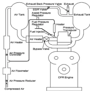
2.1 CFR Engine. A Co-operative Fuel Research 共CFR兲 en-gine was used for this research. It is a single-cylinder, variable compression ratio, four-stroke engine commonly used to evaluate the knock resistance of gasoline and the ignition quality of diesel fuels. Table 1 provides the basic specifications of the CFR engine. Figure 1 shows the schematic of the research facility.
The engine was modified from the standard ASTM setup by the addition of an air-assist port fuel injection system and other hard-ware and softhard-ware needed for the control of critical engine param-eters such as intake air temperature, air/fuel ratio 共AFR兲, exhaust gas recirculation, and intake and exhaust back pressure.
2.2 Fuel Injection. A port fuel injector for flexible fuel ve-hicles was modified to provide air-assist atomization of liquid fuels. For this study, the fuel system and air-assist pressures were
maintained at 500 kPa and 200 kPa, respectively. The injector produces droplets with a Sauter mean diameter 共SMD兲 of 15 m or less with both diesel- and gasolinelike fuels under these condi-tions. In this research, the fuel was injected into the intake mani-fold during the intake stroke. A Coriolis-effect mass flow meter 共Micro Motion, Model D6兲 was used to measure the fuel flow rate. The amount of fuel injected was controlled by adjusting the fuel injection pulse width, and feedback control was provided based on the measured fuel and air flow rates.
2.3 Intake Air and Exhaust Systems. Surge tanks were in-stalled in the intake and exhaust systems to minimize pressure pulsations of the intake and exhaust gases, thereby improving en-gine operational stability and airflow measurement. The intake air was maintained at a specified temperature by precisely controlling the power supplied to a 1.5 kW heater installed after the intake surge tank. Combustion air was supplied by regulated compressed air and mixed with the desired quantity of recirculated exhaust in the intake surge tank.
The exhaust surge tank provides complete mixing of the ex-haust gases before sampling for emissions analysis and recircula-tion into the intake manifold. A back pressure valve was installed at the exit of exhaust surge tank to create the pressure drop needed for exhaust gas recirculation 共EGR兲 operation and to simulate the back pressure of the turbocharged engine.
The total air flow rate to the engine was measured using a mass flow meter 共Sierra, model 780 Series Flat-Trak™兲. A portion of the air was diverted to assist in fuel atomization prior to entering the intake manifold.
2.4 Data Acquisition. The low-speed data acquisition system is based on National Instruments’ PXI hardware platform. The hardware is controlled by data acquisition and control software 共Sakor Technologies, Inc., DynoLAB™ PT兲, which provided stable control of the engine speed and load conditions, as well as critical parameters such as engine coolant and lubricating oil tem-peratures, intake air pressure and temperature, exhaust back pres-sure, fuel injection timing, and the quantity of fuel injected.
Cylinder pressure was measured with a high frequency-response piezoelectric pressure transducer 共Kistler Corp., model 6121兲 mounted flush with the cylinder surface using the detona-tion transducer access port. The transducer was connected to a dual mode charge amplifier 共Kistler, model 5010兲. An encoder fitted to the cam shaft provided a transistor-transistor logic 共TTL兲 signal with a resolution of 0.1 deg camshaft 共0.2 deg crankshaft兲, which was used as the data acquisition clocking pulses to acquire the pressure data and which served also as an input to the fuel and
Table 1 Engine specifications
Cylinder bore 82.55 mm
Stroke 114.3 mm
Displacement 611.7 ml
Connecting rod length 254 mm
Compression ratio 4.6–16
Combustion chamber Pancake shape
Intake valve open 10° CA ATDC
Intake valve close 36° CA ABDC
Exhaust valve open 40° CA BBDC
Exhaust valve close 5 ° CA ATDC
Fuel system Air-assist port fuel injection
blast air injection controlling hardware/software. The resultant pressure and crank angle signals were routed to a high-speed data acquisition system 共Op-timum Power Technology, model PTrAc兲, also based on National Instruments’ hardware.
2.5 Dynamometer. The engine was coupled to an eddy cur-rent dynamometer that absorbed engine load. A variable-speed ac motor, coupled to the dynamometer with an overdrive clutch, was used to start and motor the engine before stable HCCI combustion was initiated, as well as to maintain engine speed when HCCI combustion was unstable.
2.6 Experimental Procedure. Prior to each experiment, the lubricating oil and coolant systems were preheated by electric heaters to a temperature of 82° C. At the same time, the intake and exhaust systems were also preheated. HCCI combustion was eas-ily initiated after the coolant, lubricating oil, and fuel/air mixture temperatures reached the desired levels. At each operating condi-tion, the engine was run for at least 5 min or until engine opera-tion stabilized before sampling experimental data while continu-ally monitoring key operating parameters such as intake pressure and temperature, as well as brake power, brake specific fuel con-sumption 共BSFC兲 and unburned hydrocarbon 共UHC兲 and carbon monoxide 共CO兲 emissions.
At each operating condition, engine performance data and criti-cal operating parameters were collected for approximately 4 min at a sampling frequency of 1 Hz. At the same time, 500 engine working cycles were sampled, stored, and processed. The aver-aged cylinder pressure was analyzed to obtain the heat release and a complete set of combustion parameters such as CA50 and NTC delay period. Each cycle was analyzed individually and used to calculate statistical results such as the COVIMEP. In this research, pure n-heptane was used as fuel.
3 Numerical Simulation
In order to predict the combustion process of the HCCI engine, a numerical model with detailed chemistry was developed to simulate the four-stroke process. The intake stroke was simulated while accounting for the presence of residual gases and fresh charge efficiency measured experimentally. The air-fuel-diluents mixture was assumed to be an ideal gas with uniform temperature, pressure, and mixture composition. If blow-by is neglected, the energy conservation equation for the working fluid at any instant in time t, from intake valve closure to exhaust valve opening, is
dQ dt = dU dt + dW dt 共1兲
where Q is the heat transfer to the cylinder charge, U is the total internal energy of the cylinder charge, and W is work output due to piston movement. dW / dtis given by dW dt = P dV dt 共2兲
where P is the cylinder pressure, and V is the volume of the combustion chamber.
dQ / dtis given by
dQ
dt = − h · A共T − Tw兲 共3兲
where A is the surface area of the combustion chamber wall, T is the mean temperature of the charge, Twis the cylinder wall tem-perature that is assumed to be constant throughout the cycle, and
his the heat transfer coefficient. Traditionally, h is estimated using an empirical equation developed by Woschni 关18兴 and Heywood 关19兴. The equation was derived for a propagating turbulent flame, which is obviously not the case of HCCI engine. In this research, the heat transfer coefficient was calculated using formulations de-rived recently by Chang et al. 关20兴 based on spatially averaged
heat flux measurements of HCCI combustion using gasoline.
dU / dtmay be calculated as dU dt = d
兺
共Niui兲 dt =兺
Ni dui dt +兺
ui dNi dt 共4兲where Niis the number of moles of the ith species. It changes with time as a result of a chemical reaction as follows:
dNi
dt = V˙i 共5兲
where ˙i is the production rate of the ith species and can be calculated usingCHEMKINsubroutines based on the instantaneous mixture composition, temperature, and pressure. The remaining thermodynamic properties such as internal energy and specific heat capacity were also calculated usingCHEMKINwith the corre-sponding species property data reported in the literature 关21兴.
The presence of residual gases was also considered. The tem-perature and composition of the combustion products at the ex-haust valve closing of the prior engine cycle was used to calculate the residual gas composition and other properties such as enthalpy of the bulk mixture of the following cycle. After adjusting the temperature and composition of the calculated residual gases, the cycle calculation was repeated until the cylinder mixture tempera-ture from one cycle to the next varied by less than 0.5° C at the exhaust valve opening. Under normal conditions, the cylinder mixture temperature converged after three engine cycles. When the combustion process was retarded, however, it took more than five cycles to obtain a stable exhaust temperature considering the significant effect of intake temperature on HCCI combustion un-der such conditions.
3.1 Effective Fuel/Air Mixture Temperature. In this re-search, the intake air-diluent mixture temperature was measured using a thermocouple installed about 25 cm upstream of the intake valve and 5 cm upstream of fuel injector. However, the intake mixture is cooled due to fuel evaporation and then continually heated by the intake port and intake valve. Accordingly, the effec-tive fuel/air mixture temperature entering the combustion chamber must be estimated. Following the procedure recommended in lit-erature 关22兴, the effective intake templit-erature Tin,effectivewas esti-mated as follows: Tin,effective= Tin,effective,base· m˙air,base m˙air+fuel ·Mair+fuel Mair · Pin Pin,base 共6兲 where m˙air+fuel, Mair+fuel, and Pinare the mass flow rate, molar mass, and pressure of intake mixture, respectively; m˙air,base,
Mair,base, and Pin,baseare the mass flow rate, molar mass, and in-take air pressure for the base case, respectively; and Tin,effective,base is the effective intake temperature for the base case.
In principle, the base case can be any experimental condition for which the effective intake temperature can be accurately esti-mated or computed. For this study, the base case involved motor-ing the engine at a constant speed while maintainmotor-ing the intake air and lubricating oil and coolant temperatures at 82° C. Under these conditions, heat transfer between the intake mixture and the intake port and valve is minimized and the effective fuel/air mixture temperature will be close to the intake air temperature. Figure 2 shows the variation of the effective intake mixture temperature as a function of the intake air temperature with a constant AFR. For 20° C intake air temperature, the effective intake mixture ture was about 20° C higher than the measured intake air tempera-ture. The effective intake mixture temperature was equivalent to the intake air temperature with an intake air temperature of 82° C, as shown in Fig. 2.
3.2 Fuel Chemistry. A detailed chemistry, consisted of 561 species and 2539 elementary reactions, was adopted to simulate the ignition process for n-haptane-air mixtures 关21兴. This is the Journal of Engineering for Gas Turbines and Power FEBRUARY 2010, Vol. 132 / 022801-3
most detailed chemistry for n-heptane 关15,21兴 and has been shown to be suitable for HCCI engine simulations using a single-zone model 关15兴.
3.3 Validation of Numerical Simulation. The aforemen-tioned numerical simulation with detailed fuel chemistry was first validated against shock tube data reported in the literature 关21,23兴. As shown in Fig. 3, the ignition delay calculated by the model agrees well with experimental data measured under both stoichi-ometric and lean conditions over a range of temperatures and pressures 关21,23兴. This confirms that the chemistry scheme em-ployed can simulate the n-heptane oxidation process and predict the ignition delay measured in a shock tube. Accordingly, this chemistry was used in this research to examine HCCI combustion. As an example, the predicted results were also compared to pres-sure traces generated byCHEMKIN IV, a well known commercial software package, for adiabatic HCCI combustion. The model de-veloped produced identical cylinder pressure and temperature traces to those generated by CHEMKIN IVwhen heat transfer be-tween bulk gas and engine coolant was neglected. This confirms that the numerical simulation can be used to calculate the com-bustion process of HCCI engine if a suitable heat transfer equation is employed.
4 Results and Discussion
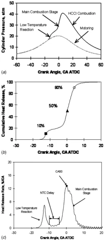
Figure 4 shows a typical HCCI combustion trace using
n-heptane. The motoring cylinder pressure is shown for compari-son purposes. As reported by many other researchers, n-heptane
combustion is characterized by a well known two-stage oxidation process. The first stage is associated with LTRs and releases a relatively small amount of energy. The second stage associated with high temperature oxidation releases most of the energy and is considered as the MCS. In this research, the crank angle duration between the end of the LTR and the beginning of the MCS is defined as the NTC delay, as shown in Fig. 4共c兲. The heat release process was characterized by the start 共10% heat release, CA10兲, middle 共50%, CA50兲, and end 共90%, CA90兲 of combustion as shown in Fig. 4共b兲. The location of 50% heat release 共CA50兲 is
Fig. 2 Variation of effective intake mixture temperature with intake air temperature: N = 900 rpm, CR= 10.0, Pin= 95 kPa, Pexh= 104 kPa, AFR= 50
Fig. 3 Ignition delay of n-heptane at moderate and high pres-sure for both lean and stoichiometric mixtures. Experimental data were obtained from Ref. †23‡.
Fig. 4 Variation of „a… cylinder pressure „HCCI and motoring…, „b… cumulative heat release, and „c… heat release rate with crank angle; CR= 10, Tin= 30° C, AFR= 50, Pin= 95 kPa
generally considered to be the most important parameter that is adjusted to optimize HCCI combustion phasing. As shown in Fig. 4共c兲, CA50 is located close to the middle of the main combustion stage. For this condition, the engine produced near-zero soot emis-sions measured by laser-induced incandescence 共Artium Tech-nologies兲 and less than 2 ppm NOxemissions 共California Analyti-cal Instruments兲, reflecting excellent HCCI combustion 关24兴.
Table 2 compares the combustion process, indicated engine per-formance and combustion stability obtained in a series of experi-ments conducted over a 2 week period under the prescribed oper-ating conditions. The data show that stable and repeatable HCCI combustion has been achieved at this operating condition. For example, the observed differences in CA10 and CA50 were within 1 ° CA and the coefficient of variation 共COV兲 in the indicated mean effective pressure 共IMEP兲 was found to be about 2%.
On the basis of these preliminary results, the experimental ap-paratus was used to investigate the effects of critical engine pa-rameters on HCCI combustion. Details of the experimental matrix are provided in Table 3. The experimental results are shown in Figs. 5–11.
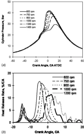
Figure 5 shows the effect of engine speed on HCCI combustion. Increasing engine speed tends to reduce cylinder pressure and retard the peak pressure location as shown in Fig. 5共a兲. This is due to a significantly retarded MCS, as shown in Fig. 5共b兲. The heat release rate during the MCS is also reduced with retarded com-bustion due to the increasing comcom-bustion chamber volume after top dead center. This leads to lower combustion chamber tempera-tures and a corresponding decrease in the oxidation reaction rates. However, the effect of engine speed on the LTR phase tends to be relatively weak, reflecting its strong dependence on temperature history. Increasing the engine speed delays the phasing of the MCS, primarily due to its effect on the NTC delay period. Figure 6 shows that the NTC delay increases linearly with increasing engine speed, reflecting the constant NTC delay period 共in sec-onds兲 under constant AFR conditions.
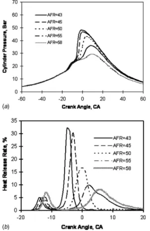
Similar to spark ignition and diesel engines, the work produced by an HCCI engine is controlled by adjusting the amount of fuel supplied. Figure 7 shows the effect of AFR on cylinder pressure and heat release rate when intake air temperature was kept con-stant. As shown in Fig. 7共a兲, the cylinder pressure increases more rapidly and reaches its peak value at an earlier crank angle when the fueling rate is increased, which corresponds to a lower AFR. The advanced MCS combined with the enhanced heat release rate,
as shown in Fig. 7共b兲, contributes to this phenomenon. Similar to the effect of engine speed, AFR does not have a large influence on the phasing of the LTR, indicating a stronger dependence on mix-ture temperamix-ture history than on mixmix-ture composition. In compari-son, increasing the AFR by reducing the fueling rate significantly retarded the phasing of the MCS. This is primarily due to the effect of leaner conditions on the NTC delay period, as shown in Fig. 8. The NTC delay increases almost linearly with increasing AFR.
The effect of turbocharging on HCCI combustion was exam-ined at a constant AFR condition. As shown in Fig. 9, boosting the
Table 2 Repeatability of HCCI engine operation „CR= 10.0, Tin
= 30° C, Pin= 95 kPa, Pexh= 104 kPa, AFR= 50…
Test No. CA10a CA50a CA90a
IMEP 共bar兲 COVIMEP 共%兲 ISFC 共g / kW h兲 1 ⫺11.72 0.20 2.80 3.42 2.3 213.1 2 ⫺12.53 0.68 5.47 3.28 2.0 221.6 3 ⫺12.41 0.24 4.42 3.34 2.0 215.2 4 ⫺12.53 ⫺0.33 3.45 3.41 2.2 213. 6 a°CA ATDC.
Table 3 Experiment matrix
Test No. Speed 共rpm兲 AFR 共mass兲 CR Tin,air 共°C兲 Pin 共kPa兲 1 600–1400 50 10.0 40 95 2 900 43–63 10.0 40 95 3 900 50 9–16 30 95 4 900 50, 60 10.0 25–100 95 5 900 60 10.0 40 95–200 6a 900 20–60 10.0 40 40–95
aConstant fuel flow rate.
Fig. 5 Effect of engine speed on „a… cylinder pressure and „b… heat release rate: CR= 10.0, AFR= 50, Tin,air= 40° C, Pin= 95 kPa, Pexh= 104 kPa
Fig. 6 Effect of engine speed on NTC delay: CR= 10.0, Tin,air = 40° C, Pin= 95 kPa, Pexh= 104 kPa, fuel: n-heptane, AFR= 50.
intake pressure tends to significantly increase the cylinder pres-sure during the compression stroke. Since the quantity of fuel injected is increased as intake pressure increases to maintain a constant AFR, the LTR stage is advanced and intensified. This leads to a shorter NTC delay period and significantly advances phasing of the MCS, as shown in Fig. 9共b兲. Figure 10 shows that increasing the intake pressure significantly reduces the NTC delay period as the intake pressure is increased from 80 kPa to 120 kPa. Boosting the intake pressure beyond 120 kPa continued to reduce the NTC delay period, but the rate of decrease in the NTC delay period was lower.
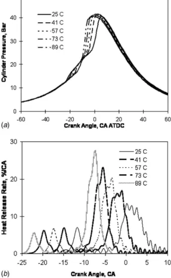
Intake temperature is the most critical and widely used engine operation parameter to control the phasing of HCCI combustion.
Figure 11 shows the effect of intake temperature on HCCI com-bustion for a constant AFR of 50. Stable HCCI comcom-bustion was obtained for a wide range of temperatures. As shown in Fig. 11共b兲, increasing the intake temperature advances the phasing of both the LTR and MCS. The LTR heat release profiles were found to be quite similar, although they were advanced as temperature in-creased. However, increasing the intake temperature significantly enhances the heat release rate of the MCS. The increasingly ad-vanced phasing of the MCS contributes to the increased heat re-lease rate. As shown in Fig. 12, intake temperature does not have a large influence on the NTC delay period.
Figure 13 shows that increasing the compression ratio advances the combustion process and increases the peak cylinder pressures.
Fig. 7 „a… Cylinder pressure; „b… heat release rate. Effect of air-fuel ratio on HCCI combustion: CR= 10.0, Tin,air= 40° C, Pin
= 95 kPa, Pexh= 104 kPa, N = 900 rpm.
Fig. 8 Effect of air-fuel ratio on NTC delay: CR= 10.0, Tin,air = 40° C, Pin= 95 kPa, Pexh= 104 kPa, N = 900 rpm
Fig. 9 „a… Cylinder pressure; „b… heat release rate. Effect of turbocharging on HCCI combustion: CR= 10, Tin,air= 40° C, AFR
= 60.0, N = 900 rpm.
Fig. 10 Effect of turbocharging on NTC delay: CR= 10, Tin,air = 40° C, AFR= 60.0, N = 900 rpm
This is primarily due to the effect of increased compression tem-peratures and pressures as the compression ratio increases, which enhances n-heptane oxidation. As shown in Fig. 13共b兲, the phas-ing of both LTR and MCS phases were advanced with increasphas-ing compression ratio. Figure 14 shows that increasing the compres-sion ratio from 9 to 10 dramatically decreased the NTC delay
period. For a compression ratio of 11, the MCS was advanced beyond top dead center. Increasing the compression ratio beyond 11 had a negligible effect on the NTC delay period. The combus-tion phasing of the LTR and MSC were advanced by a comparable amount as compression ratio was increased beyond 11.
HCCI combustion tends to become unstable and incomplete when the MCS is retarded excessively. In these cases, the com-bustion phasing can be advanced by heating the intake mixture to a higher temperature or increasing the compression ratio. As
re-Fig. 11 „a… Cylinder pressure; „b… heat release rate. Effect of intake air temperature on HCCI combustion: N = 900 rpm, CR = 10.0, Pin= 95 kPa, Pexh= 104 kPa, AFR= 50.
Fig. 12 Effect of intake air temperature on NTC delay: N = 900 rpm, CR= 10.0, Pin= 95 kPa, Pexh= 104 kPa, AFR= 50
Fig. 13 „a… Cylinder pressure; „b… heat release rate. Effect of compression ratio on HCCI combustion: Tin,air= 30° C, Pin = 95 kPa, Pexh= 104 kPa, N = 900 rpm, AFR= 50.
Fig. 14 Effect of compression ratio on NTC delay: Tin,air = 30° C, Pin= 95 kPa, Pexh= 104 kPa, N = 900 rpm, AFR= 50
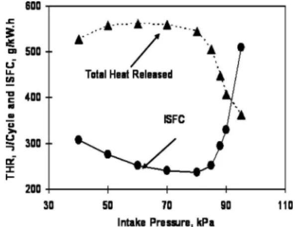
ported in the literature 关25兴, enriching the air/fuel mixture under lean operation can enhance the oxidation reaction rates. The ex-periments that examined AFR effects on HCCI combustion in this study demonstrated that a relatively richer mixture helps to ad-vance the combustion phase and accelerate the oxidation process to achieve complete combustion. Traditionally, enriching the in-take mixture is achieved by injecting more fuel into the inin-take air. However, this same effect may also be obtained by throttling the intake air while keeping the fuel flow rate constant. Figure 15 shows the effect of intake air throttling on HCCI combustion un-der a constant fuel flow rate condition. Late and incomplete com-bustion was encountered with 95 kPa intake pressure, which is reflected by a relatively weak MCS and reduced heat release dur-ing the combustion process. Throttldur-ing the intake air enhanced the heat release during the MCS, although its effect on the combus-tion phasing of the LTR is relatively weak, as shown in Fig. 15共b兲. Intake air throttling can help to burn the fuel completely as indi-cated by the increased total heat release and reduced indiindi-cated specific fuel consumption 共ISFC兲, as shown in Fig. 16. Throttling the intake air enables complete combustion even though the MCS occurs after top dead center. The presence of less excess air 共a diluent兲 in the combustion chamber helps to increase the bulk gas temperature and enhance the oxidation process during the MCS. However, overthrottling the intake pressure tends to delay the MCS again. This is due to the effect of cylinder pressure on the combustion process, as well as the increasing role played by
re-sidual gases, which tends to deteriorate the oxidation process and retard the main combustion phase 关26兴. As shown in Fig. 16, ISFC increases when the intake pressure is overthrottled. This is due to increased pumping losses and the reduced oxidation rate associ-ated with having a higher fraction of residual gases.
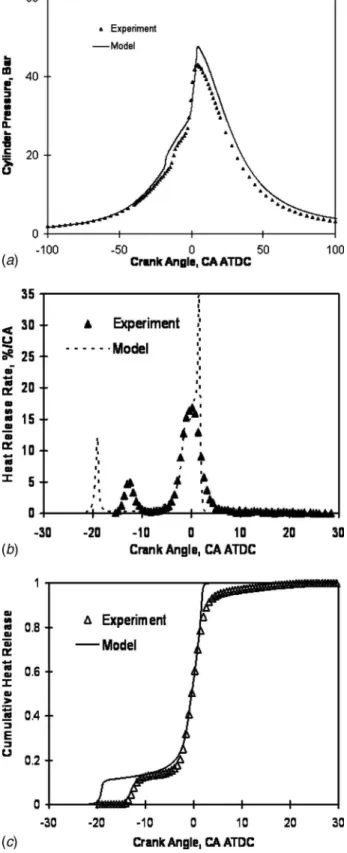
The aforementioned single-zone numerical model was used to simulate the HCCI combustion process. Figure 17 compares the predicted cylinder pressure, heat release rate, and cumulative heat release with those measured experimentally. For comparison pur-poses, the effective intake mixture temperature used in the simu-lation was adjusted such that the calculated CA50 matched experi-mental data. The effective intake temperature used in the numerical simulation was 350 K compared with the experimental value of 319.5 K as calculated by Eq. 共6兲. Other researchers have reported a need to adjust the intake mixture temperature in mod-eling HCCI combustion. For example, Yelvington et al. 关27兴 re-ported that the intake temperature adjustment was approximately 30 K in order to match the predicted phasing of the heat release with experimental data. This is likely due to the imperfect as-sumption of a homogeneous air/fuel mixture with uniform tem-perature, pressure, and reaction rate, as well as potential limita-tions of the fuel chemistry. The assumption of uniform and constant combustion chamber wall temperature during the whole engine cycle may also contribute to the requirement to adjust the intake mixture temperature. Intake mixture temperature adjust-ments have also been used in multizone models to account for nonuniformities of the mixture temperature. For example, an ini-tial temperature difference between the core and outer boundary zones in one multizone numerical simulation was reported to be ⬃35 K to achieve reasonable predictions of cylinder pressure and combustion phasing 关28,29兴.
As shown in Fig. 17, the numerical simulation was able to capture elements of HCCI combustion of n-heptane, particularly the phasing of the MCS. In comparison, the LTR predicted by the numerical simulation is advanced compared to the experimental data as shown in Figs. 17共b兲 and 17共c兲. A spike in the predicted heat release rate was observed during the MCS. This spike was caused by the rapid oxidation of all CO accumulated to this point in the simulation to CO2. The conversion of CO to CO2is pre-dicted to happen rapidly once the required temperature is reached because only a few reactions are involved. Rapid oxidation of CO to CO2has not been observed experimentally or reported in the oliterature. The assumption of uniform mixture temperature and mixture composition contributes to this overly-rapid heat release rate.
For this research, a single adjustment was made to the effective intake mixture temperature and then applied to all operating
con-Fig. 15 „a… Cylinder pressure; „b… heat release rate. Effect of intake air throttling on HCCI combustion at constant intake fuel flow rate: N = 900 rpm, CR= 10.0, Tin,air= 40° C, Pexh= 104 kPa, m˙
fuel= 0.273 kg/ h, AFR= 20– 60.
Fig. 16 Effect of throttling intake air on total heat release and indicated specific fuel consumption when intake fuel flow rate was kept constant: N = 900 rpm, CR= 10.0, Tin,air= 40° C, Pexh
= 104 kPa, m˙
ditions. On this basis, this model was shown to be able to capture the effect of compression ratio on the combustion phasing of HCCI combustion using n-heptane. Figure 18 compares the pre-dicted CA50 with those measured experimentally for different compression ratios while keeping the AFR constant at 50. The predicted CA50 combustion phasing was found to agree well with
the experimental measurements. It was found that CA50 retards almost linearly with decreasing CR for high compression ratios 共CR⬎ 11兲. However, the CA50 retards rapidly when the compres-sion ratio is reduced below 10, reflecting an increasing sensitivity for n-heptane when CA50 occurs after top dead center.
Figure 19 shows that the numerical simulation is able to capture the approximately linear trend of CA50 retardation as engine speed increases.
Finally, the effect of turbocharging on CA50 may be seen in Fig. 20. For this figure, the effective intake mixture temperature in the numerical simulation was adjusted to match the experimental data when the intake pressure was 95 kPa. Figure 20 shows that the numerical simulation is able to capture the trend of advanced
Fig. 17 Comparison of predicted „a… cylinder pressure, „b… heat release rate, and „c… cumulative heat release with experi-mental data: CR= 10, Tin,air= 30° C, AFR= 50, Pin= 95 kPa
Fig. 18 Comparison of the predicted CA50 with those deter-mined experimentally over a range of compression ratios. Op-erating condition is the same as Fig. 13.
Fig. 19 Comparison of the predicted CA50 with those deter-mined experimentally over a range of engine speeds. Operating condition is the same as in Fig. 5.
Fig. 20 Comparison of the predicted CA50 with those deter-mined experimentally over a range of intake pressures. Oper-ating condition is the same as in Fig. 9.
CA50 as intake pressure increases. However, the predicted CA50 is retarded relative to the experimental data at higher intake pres-sures. The assumption that the combustion chamber wall tempera-ture is not a function of engine load may be responsible for this difference. Since the combustion chamber wall temperature likely increases with increasing load, incorporating a variable combus-tion wall temperature should improve the prediccombus-tions of CA50 under turbocharged conditions.
5 Conclusions
A CFR engine was modified to investigate HCCI combustion characteristics over a wide range of operating conditions. In par-ticular, a port fuel injection system was implemented for atomiz-ing n-heptane for this study. Based on the experimental data and complementary numerical simulations of HCCI combustion, the following conclusions may be drawn.
• Increasing the intake air temperature and compression ratio advances the phasing of both the low-temperature reaction and main combustion stage. In comparison, the effects of AFR, engine speed, and turbocharging on the phasing of low-temperature reaction are relatively weak, but they sig-nificantly affect the phasing of the main combustion stage. • The NTC delay period is a strong function of engine speed,
air/fuel ratio, and intake pressure 共at constant air/fuel ratio兲. The effect of intake temperature 共at constant air/fuel ratio兲 on the NTC delay period is not as strong as those previously described. In comparison, the effect of compression ratio on NTC delay is negligible except for low compression ratios when the combustion phasing is very retarded.
• Throttling the intake air while keeping fuel flow rate con-stant tends to improve HCCI combustion when incomplete combustion is observed. It is believed that the resultant en-richment of the air/fuel mixture contributes to this desirable characteristic. However, overthrottling tends to retard the main combustion stage and deteriorate engine performance even though relatively complete combustion can still be ob-tained at a later combustion phasing.
• The validated numerical simulation was able to capture trends in combustion phasing variation with critical engine parameters. The calculated CA50 was found to agree well with those measured experimentally over a wide range of engine compression ratios, speeds, and intake pressures. Acknowledgement
The financial support of the Government of Canada’s PERD/ AFTER and Climate Change T&II programs are gratefully ac-knowledged. The technical contribution of Mr. M. F. Baksh in constructing the fuel delivery system is acknowledged.
References
关1兴 Epping, K., Aceves, S. M., Bechtold, R. L., and Dec, J. E., 2002, “The Poten-tial of HCCI Combustion for High Efficiency and Low Emissions,” SAE Paper No. 2002-01-1923.
关2兴 Zhao, F., Asmus, T, Assanis, D., Dec, J., Eng, J., and Najt, P, 2003, “Homo-geneous Charge Compression Ignition 共HCCI兲 Engines: Key Research and Development Issues,” Society of Automotive Engineers, Inc., SAE Paper No. PT-94.
关3兴 Onishi, S., Jo, S. H., Shoda, K., Jo, P. D., and Kato, S., 1979, “Active Thermo-Atmosphere Combustion 共ATAC兲–A New Combustion Process for Internal Combustion Engines,” SAE Paper No. 790501.
关4兴 Noguchi, M., Tanaka, Y., Tanaka, T., and Takeuchi, Y., 1979, “A Study on Gasoline Engine Combustion by Observation of Intermediate Reactive Prod-ucts During Combustion,” SAE Paper No. 790840.
关5兴 Najt, P. M., and Foster, D. E., 1983, “Compression-Ignited Homogeneous Charge Combustion,” SAE Paper No. 830264.
关6兴 Chen, R. and Milovanovic, N., 2001, “A Review of Experimental and Simu-lation Studies on Controlled Auto-Ignition Combustion,” SAE Paper No. 2001-01-1890.
关7兴 Yang, J., Culp, T., and Kenney, T., 2002, “Development of a Gasoline Engine System Using HCCI Technology—The Concept and the Test Results,” SAE Paper 2002-01-2832.
关8兴 Christensen, M., Hultqvist, A., and Johansson, B., 1999, “Demonstrating the Multi-Fuel Capability of a Homogeneous Charge Compression Ignition Engine With Variable Compression Ratio,” SAE Paper No. 1999-01-3679. 关9兴 Kalghatgi, G. T., 2005, “Auto-Ignition Quality of Practical Fuels and
Implica-tion for Fuel Requirements of Future SI and HCCI Engines,” SAE Paper No. 2005-01-0239.
关10兴 Amann, M., Ryan, T. W., and Kono, N., 2005, “HCCI Fuels Evaluations-Gasoline Boiling Range Fuels,” SAE Paper No. 2005-01-3727.
关11兴 Ryan, T.W., Callahan, T.J., and Mehta, D., 2004, “HCCI in a Variable Com-pression Ratio Engine—Effects of Engine Variables,” SAE Paper No. 2004-01-1971.
关12兴 Zhong, S., Megaritis, A., Yap, D., and Xu, H., 2005, “Experimental Investiga-tion Into HCCI CombusInvestiga-tion Using Gasoline and Diesel Blended Fuels,” SAE Paper No. 2005-01-3733.
关13兴 Li, Y., Zhao, H., Brouzos, N., Ma, T., and Leach, B., 2006, “Effect of Injection Timing on Mixture and CAI Combustion in a GDI Engine With an Air-Assisted Injector,” SAE Paper No. 2006-01-0206.
关14兴 Easley, W., Agarwal, A., and Lavoie, G. A., 2001, “Modeling of HCCI Com-bustion and Emissions Using Detailed Chemistry,” SAE Paper No. 2001-01-1029.
关15兴 Naik, C., Pitz, W. J., Sjoberg, M., Dec, J. E., Orme, J., Curran, H., Simmie, J. M., and Westbrook, C. K., 2005, “Detailed Chemical Kinetic Modelling of Surrogate Fuels for Gasoline and Application to an HCCI Engine,” SAE Paper No. 2005-01-3741.
关16兴 Xu, H., 2005, “Modelling of HCCI Engines: Comparison of Single-Zone, Multi-Zone and Test Data,” SAE Paper No. 2005-01-2123.
关17兴 Kongsereeparp, P., Kashani, B., and Checkel, M. D., 2005, “A Stand-Alone Multi-Zone Model for Combustion in HCCI Engines,” ASME ICED 2005 Fall Technical Conference, Ottawa, Canada, Sept.11–14, ASME Paper No. ICEF2005-1241.
关18兴 Woschni, G., 1967, “A Universal Applicable Equation for the Instantaneous Heat Transfer Coefficient in the Internal Combustion Engines,” SAE Paper No. 670971.
关19兴 Heywood, J. B., 1988, Internal Combustion Engine Fundamentals, McGraw-Hill, New York.
关20兴 Chang, J., Guralp, O., Asanis, D., Kuo, T., Najt, P., and Rask, R., 2004, “New Heat Transfer Correlation for an HCCI Engine Derived From Measurements of Instantaneous Surface Heat Flux,” SAE Paper No. 2004-01-2996.
关21兴 Curran, H. J., Gaffuri, P., Pitz, W. J., and Westbrook, C. K., 1998, “A Com-prehensive Modeling Study of n-Heptane Oxidation,” Combust. Flame, 114, pp. 149–177.
关22兴 Sjöberg, M., and Dec, J.E., 2004, “An Investigation of the Relationship Be-tween Measured Intake Temperature, BDC Temperature, and Combustion Phasing for Premixed and DI HCCI Engines,” SAE Paper No. 2004-01-1900. 关23兴 Ciezki, H. K., and Adomeit, G., 1993, “Shock-Tube Investigation of Self-Ignition of n-Heptane-Air Mixtures Under Engine Related Conditions,” Com-bust. Flame, 93, pp. 421–433.
关24兴 Li, H. L., Neill, W. S., Chippior, W., Graham, L., Connolly, T., and Taylor, J. D., 2007, “An Experimental Investigation on the Emission Characteristics of HCCI Engine Operation Using n-Heptane,” SAE Paper No. 2007-01-1854. 关25兴 Glassman, I., 1987, Combustion, Academic Press, New York.
关26兴 Peng, Z., Zhao, H., and Ladommatos, N., 2003, “Effect of Air/Fuel Ratios and EGR Rates on HCCI Combustion of n-Heptane, a Diesel Type Fuel,” SAE Paper No. 2003-01-0747.
关27兴 Yelvington, P. E., Rallo, M. B., Liput, S., Tester, J. W., Green, W. H., and Yang, J., 2004, “Prediction of Performance Maps for Homogeneous-Charge Compression-Ignition Engines,” Combust. Sci. Technol., 176, pp. 1243–1282. 关28兴 Kongsereeparp, P. and Checkel, M. D., 2007, “Novel Method of Setting Initial Conditions for Multi-Zone HCCI Combustion Modeling,” SAE Paper No. 2007-01-0674.
关29兴 Kongsereeparp, P. and Checkel, M. D., 2007, “Investigating the Effects of Reformed Fuel Blending in a Methane- or n-Heptane-HCCI Engine Using a Multi-Zone Model,” SAE Paper No. 2007-01-0205.