HAL Id: hal-00317595
https://hal.archives-ouvertes.fr/hal-00317595
Submitted on 30 Mar 2005
HAL is a multi-disciplinary open access
archive for the deposit and dissemination of
sci-entific research documents, whether they are
pub-lished or not. The documents may come from
teaching and research institutions in France or
abroad, or from public or private research centers.
L’archive ouverte pluridisciplinaire HAL, est
destinée au dépôt et à la diffusion de documents
scientifiques de niveau recherche, publiés ou non,
émanant des établissements d’enseignement et de
recherche français ou étrangers, des laboratoires
publics ou privés.
Effects of along- and cross-radar-beam winds on Doppler
radar spectrum
Y.-H. Chu
To cite this version:
Y.-H. Chu. Effects of along- and cross-radar-beam winds on Doppler radar spectrum. Annales
Geo-physicae, European Geosciences Union, 2005, 23 (3), pp.681-692. �hal-00317595�
SRef-ID: 1432-0576/ag/2005-23-681 © European Geosciences Union 2005
Annales
Geophysicae
Effects of along- and cross-radar-beam winds on Doppler radar
spectrum
Y.-H. Chu1
1Institute of Space Science/Center for Space and Remote Sensing Research, National Central University, Chung-Li, Taiwan Received: 27 August 2004 – Revised: 30 August 2004 – Accepted: 21 December 2004 – Published: 30 March 2005
Abstract. Beam broadening effects on the Doppler radar
spectrum induced by along- and cross-radar-beam winds are theoretically investigated in this article. Analytical expres-sion of beam broadening spectrum for a vertical beam sub-ject to a constant vertical wind in the absence of horizontal wind is derived first. We find that the resultant beam broad-ening spectral shape is in an exponential form, rather than a Gaussian shape. The peak of the exponential spectrum cor-responds to the true vertical wind velocity, and the spectral width σ is a function of vertical wind velocity w and the half-power beam width θ1/2of the radar beam, in accordance with the expression σ =0.09wθ1/22 . The beam broadening spec-trum for a vertical radar beam subject to both vertical and horizontal winds is numerically studied, and the result shows that the spectral shape is distorted from the Gaussian form. The estimated vertical wind velocity of the distorted spec-trum is very close to the true vertical wind velocity with a difference of less than 0.6% for a typical case. However, its spectral width is substantially greater than that of the con-ventional Gaussian spectrum broadened by horizontal wind only. The difference of the spectral widths 1σ (in unit of percentage) in the two, as a function of the half-power beam width and the ratio of vertical to horizontal wind velocities, can be well approximated by a parabolic equation. With this equation and the conventional Gaussian beam broaden-ing spectral width caused by horizontal wind, the true width of the distorted beam broadening spectrum induced by ver-tical and horizontal winds can be inferred without compli-cated numerical computation. Through a transformation of wind velocity from vertical and horizontal winds into along-and cross-radar-beam winds defined on the cross section of an oblique radar beam, the results obtained from the case of vertical radar beam can be directly applied to the case of the oblique beam. We show that in some special cases the beam broadening spectral widths of an oblique beam sub-ject to both vertical and horizontal winds will be exceedingly narrower than those estimated by the existing formula, irre-spective of the presence of strong horizontal wind velocity.
Correspondence to: Y.-H. Chu (yhchu@jupiter.ss.ncu.edu.tw)
Keywords. Radio science (Atmospheric propagation) –
Me-teorology and atmospheric dynamics (Instruments and tech-nique) – General or miscellaneous (technique applicable in three or more fields)
1 Introduction
It is well recognized that the background wind in the illu-minating region of a Doppler radar with finite antenna beam width plays a crucial role in dominating the behavior of the Doppler spectrum for the radar returns generated from diffu-sive targets in the atmosphere, including turbulence-induced refractivity fluctuations and hydrometeors. The effect of the background wind on the Doppler radar spectrum is attributed to the fact that the diffusive targets drifting with background wind may have radial velocities depending on wind veloc-ity and the angular positions of the targets in the scattering volume. As a result, the observed Doppler spectrum will be broadened owing to the radar returns consisting of the signals at various Doppler frequencies that correspond to the radial velocities of the targets located in the different positions in the scattering volume. This broadening effect on the breadth of the Doppler spectrum caused simply by background wind and the antenna beam width is called the beam broadening ef-fect and the resulting Doppler spectrum, without containing the information of atmospheric targets, is termed as the beam broadening spectrum (Hocking, 1983). In this sense, the beam broadening spectrum can be interpreted as the result of the radar returns from idealized targets that are equal in size and isotropic in shape and distribute uniformly without ran-dom motion in the scattering volume. Obviously, the width of the beam broadening spectrum is a function of the antenna beam width and background wind velocity, and bears no re-lation to the characteristics of real atmospheric targets.
The relation between the beam broadening spectrum and the observed Doppler spectra from various atmospheric tar-gets have long been the topics of interest in the Doppler radar community. For example, considering the beam broad-ening effect, Hocking (1983) established a method to esti-mate clear-air turbulent strength from the observed Doppler
682 Y.-H. Chu: Effects of along- and cross-radar-beam winds on Doppler radar spectrum spectral width. Wakasugi et al. (1986) proposed a
decon-volution algorithm to remove clear-air turbulence and beam broadening effects from the observed precipitation Doppler spectrum to correctly estimate the raindrop size distribution. With the help of the beam broadening effect on clear-air tur-bulent spectrum, Chu et al. (1990) developed a method to measure the aspect sensitivity of VHF backscatter made by a vertically pointed radar beam with a relatively large beam width. Recently, Nastrom and Eaton (1997) proposed a cor-rection formula, in which the effects of beam broadening, gravity wave broadening and wind shear broadening are con-sidered, to estimate the turbulence eddy dissipation coeffi-cient from the oblique Doppler spectral width to avoid the plausible spectral narrowing effects due to specular reflec-tions.
Although the beam broadening effects on the Doppler spectra for various targets have been investigated extensively for years, almost all of the studies take advantage of beam broadening spectrum due to horizontal wind and ignore the plausible contributions of vertical wind (or along-radar-beam wind) to the Doppler spectral width (Sloss and Atlas, 1968; Hocking, 1986; Nastrom, 1997). To the author’s knowl-edge, the investigation of along-radar-beam wind effects on the shape and width of the Doppler radar spectrum has not been documented in literature. For the vertical radar beam, the effect of the along-radar-beam (or vertical) wind on the Doppler spectral width can be ignored for quiet conditions. This is because under this condition the vertical air velocity is very weak (less than a few m s−1)and the ratio of vertical w to horizontal U wind velocity is very small (in order of mag-nitude of 10−2), leading to the corresponding beam broad-ening spectral width which is 2 orders of magnitude smaller than that caused by horizontal wind (Chu, 2002). However, it may not be the case for an oblique radar beam under dis-turbed conditions. Observations made by radars and aircrafts both show that the magnitude of the vertical wind velocity associated with a thunderstorm can be as large as 20 m s−1 (Batton and Theiss, 1966; Brandes et al., 1995). Moreover, considerably strong vertical wind velocity associated with a thunderstorm usually is accompanied by a weak horizontal flow to favor the growth of the storm, suggesting a very large ratio of w to U (Nelson, 1983; Ziegler, 1983; Brandes et al., 1995). Therefore, in the presence of intense vertical wind velocity and/or a large ratio of w to U , one might expect that the effects of vertical wind on the Doppler radar spec-trum for a oblique radar beam may be substantial and should be taken into account in interpreting the behavior of the ob-served Doppler spectral width. One of the objectives of this research is to quantitatively investigate to what extent is the effect of the vertical wind.
Generally, the contour of radial velocity in resolution vol-ume is treated as a straight line to facilitate the mathemat-ical manipulation in the theoretmathemat-ical derivation of the beam broadening spectral width (Sloss and Atlas, 1968; Nastrom, 1997; Chu, 2002). Analysis indicates that this straight line approximation is valid under the conditions of a low ratio of wto U (smaller than about 0.3), together with a slight tilt
angle of the oblique beam (less than about 20◦) (Chu, 2002).
However, for the conditions of a high ratio of w to U and a large zenith angle of the radar beam, the curved nature of the radial velocity contour should be taken into account in the theoretical development of the corresponding beam broad-ening spectral width, and the shape of the beam broaden-ing spectrum will be non-Gaussian. Numerical results pre-sented in this article show that the estimated width of the non-Gaussian beam broadening spectrum is greater than that cal-culated from the conventional Gaussian spectrum, implying that the atmospheric parameters retrieved from the observed Doppler spectral width will be overestimated if the conven-tional Gaussian beam broadening spectrum is employed for the estimation.
This article is an attempt to theoretically study the effects of along-radar-beam and cross-radar-beam winds on the be-havior of the Doppler radar spectrum for vertical and oblique radar beams. We find that the shape of the beam broadening spectrum for a vertical radar beam subject to a vertical wind is in an exponential form, with a tail extending toward the lower Doppler frequency end, and its spectral width (defined as the second moment of the spectrum) as a function of the product of the vertical wind velocity and the square of the half-power beam width which is considerably smaller than that caused by the horizontal wind. Moreover, we also show in this article that the beam broadening spectral width of an oblique beam may be exceedingly narrow, if the radar beam is subject to specific vertical and horizontal winds such that the composite cross-radar-beam wind velocity is negligibly small and the along-radar-beam wind velocity is relatively large.
This paper is organized as follows. The analytical expres-sion of the beam broadening spectrum caused by a vertical wind in the absence of the horizontal wind will be derived theoretically in Sect. 2. In Sect. 3, the beam broadening spectrum of a vertical beam induced by a horizontal wind, in combination with vertical winds, is investigated. In light of the difficulty in the theoretical derivation of the exact ex-pression, a numerical simulation technique is developed in this section to obtain the desired beam broadening spectrum for different combinations of vertical and horizontal winds. Empirical relations between estimation errors of the vertical wind velocity and the beam broadening spectral width are es-tablished in this section as well. The transformation of wind velocity for the application of the vertical beam results to the case of the oblique beam is made in Sect. 4. Section 5 con-tains the discussion and Sect. 6 is the conclusion.
2 Beam broadening spectrum caused by vertical wind
In this section, an analytical expression of the beam broad-ening spectrum for a vertical radar beam subject to vertical wind is derived. In light of the fact that the beam broaden-ing spectrum is governed only by background wind and radar beam width, the characteristics of the atmospheric target are not considered in the derivation. Moreover, the background
Y.-H. Chu: Effects of along- and cross-radar-beam winds on Doppler radar spectrum 683 wind velocity is assumed to be constant and uniform in the
resolution volume and no random fluctuation of the velocity is included. In addition, the scatterers with equal size and isotropic shape are assumed to distribute uniformly in res-olution volume, leading to a uniform reflectivity across the radar beam. Although a vertically pointed radar beam is con-sidered here, we will show in Sect. 4 that the results obtained in this section can directly apply to the case of the oblique beam through appropriate transformation of wind velocities. It is noteworthy that the analytical expression of the beam broadening spectrum can theoretically be obtained by inte-grating radar power along the contour of the constant ra-dial velocity (or Doppler frequency) in the resolution vol-ume. Mathematically, the total power received by a vertically pointed radar in a given Doppler frequency shift interval from f to f +df can be formulated below (Sloss and Atlas, 1968; Chu, 2002)
SV(f )df =
Z
50g0Gb(θ, 8)dA(θ, 8), (1)
where SV(f )is the beam broadening power spectral density,
50is reflectivity that is assumed to be uniformly distributed in the resolution volume, g0=C/R2is for the far field con-dition and C is a constant determined by radar parameters, including transmitted power, radar wavelength, radar effi-ciency, and so on, Gb(θ, 8)is two-way antenna beam power
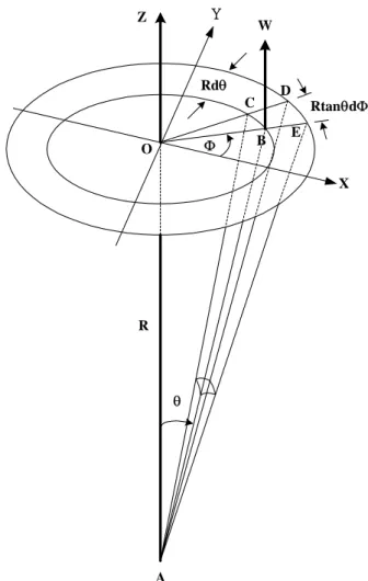
pattern, dA is an infinitesimal area at coordinate (θ ,8), f is the Doppler frequency shift, θ is zenith angle, and 8 is the azimuth angle with respect to the reference axis. The key issue in deriving the beam broadening spectrum is to find the mathematical relations between θ , 8 and f . Fig-ure 1 presents the geometric relationship between vertically pointed antenna beam and the vertical wind w, in which the horizontal plane defined by axes X (toward due east) and Y (toward due north) represents a cross section of radar volume and axis X is adopted as a reference axis in the following derivation. Let point B be located on the plane with angular coordinate (θ , 8). From Fig. 1, the relations between (x, y) and (θ , 8) can be expressed as follows:
x = Rtan θ cos 8, (2)
y = Rtan θ sin 8, (3)
where R is the height of the horizontal plane. It is easy to show that the area dA of an infinitesimal region for a quadri-lateral BCDE can be represented in terms of R, θ and 8 as follows:
dA = R2tan θ dθ d8. (4)
It is noteworthy from Fig. 1 that dA defined in Eq. (4) repre-sents an infinitesimal area of a circular annulus in the radar beam in the angular range θ −θ +dθ . To proceed, a Gaussian antenna beam pattern with circular symmetry for a monos-tatic radar is assumed and its two-way antenna beam power pattern in the rectangular coordinate is given below to sim-plify the mathematical manipulation
Gb(x, y) = e−(x 2+y2)/σ2 . (5) RtanθdΦ Rdθ R A O θ B W Y X C D E Φ Z Figure 1
Fig. 1. Geometric relationship between vertically directed antenna beam and vertical wind for the derivation of beam broadening spec-trum caused by vertical wind velocity W .
Note that σ in Eq. (5) is related to the half-power beam width θ1/2of a one-way antenna beam as follows:
σ = Rθ1/2 2
√
2 ln 2. (6)
Substituting Eq. (2)−Eq. (6) into Eq. (1), we have SV(f )df =
Z 2π 0
G0e−(Rtan θ )2/σ2R2tan θ d8dθ, (7)
where G0=g050 and SV(f ) is the beam broadening
spec-tral density induced by a uniform vertical wind in a ver-tically pointed radar beam. Note that the integration in Eq. (7) is performed only along 8 such that the connec-tion between the power SV(f )df in the given interval f to
f +dfand that in the radar beam in an annulus with infinites-imal area 2π R2tan θ dθ in the corresponding angular interval θ −θ+dθ , as obtained from Eq. (4), can be established. As-sume further that the antenna beam width is so small that the approximation tan θ ∼=sin θ ∼=θ is valid. As a result, Eq. (7) reduces to
SV(f )df = ce−(Rsin θ )
2/σ2
684 Y.-H. Chu: Effects of along- and cross-radar-beam winds on Doppler radar spectrum 26 19.20 19.4 19.6 19.8 20 20.2 20.4 20.6 20.8 21 0.1 0.2 0.3 0.4 0.5 0.6 0.7 0.8 0.9 1 Doppler Velocity (m s -1)
Normalized Power Spectral Density
HPBW=7.4 o
Radar Wavelength=5.77 m Vertical Velocity=20 m s -1
Figure 2
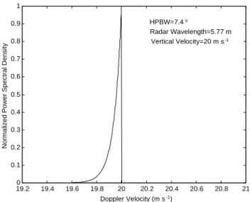
Fig. 2. Example of normalized beam broadening spectrum caused solely by vertical wind, in which a radar wavelength of 5.77 m (cor-responding to 52 MHz), radar beam with half-power beam width of 7.4◦and 20 m s−1vertical wind velocity are employed in the calcu-lation.
where c(=2π C50)is a constant independent of the height R. From Fig. 1, the relation between radial velocity Vr, vertical
wind velocity w, and zenith angle θ can be found easily as seen below
Vr =wcos θ. (9)
Equation (9) implies that for a uniformly distributed w in the radar volume, the contour of the Doppler velocity in the radar volume is a set of concentric circles with maximum value at zenith direction. This is one of the reasons why the integra-tion of Eq. (7) is performed over the domain 8 from 0 to 2π with respect to a fixed θ . Notice that the vertical veloc-ity here is assumed to be upward; Vr, therefore, is positive
in Eq. (9). Again, under the assumption of small radar beam width, Eq. (9) can be simplified as
Vr ∼=w(1 −
θ2
2 ). (10)
By employing the relation between radial velocity and Doppler frequency, namely, Vr=−f λ/2, where λ is the radar
wavelength, Eq. (10) becomes θ2∼=2 + f λ
w . (11)
Taking the differential on both sides of Eq. (11) and substitut-ing into Eq. (8), we obtain the normalized beam broadensubstitut-ing spectrum
SB(f ) = e−(f +
2w
λ)/σB2, (12)
where SB(f )=SV(f )/S0, S0=cλ/(2|w|), and
σB2=|w|θ1/22 /(8λ ln 2). Because the direction of the vertical wind velocity w determines the sign of the Doppler
frequency, there is a limitation imposed on the range of f in Eq. (12), namely, 0≤f ≤2|w|/λ if w≤0 or −2w/λg f ≤0, if w≥0. It should be noted that, except for the procedure mentioned above, there is another way to evaluate the beam broadening spectrum. One can define a spectrum of the velocity variations, which, in turn, is reflected in the measured Doppler frequency spectrum. This is the integral over the product of gain (antenna pattern as a function of zenith and azimuth angle) and the scalar product of the three-dimensional vector of atmospheric velocity and the unit radial direction vector. It also yields all information for any sets of three dimensional wind vectors (and fluctuating cross sections as well), and can also be applied for oblique antenna beams as well. However, for this purpose, one has to first develop the analytic relation between the Doppler frequency and the theta and phi in the illuminating region for the integral. Clearly, it is not an easy task, especially when the oblique radar beam and the three-dimensional wind field are considered (Chu, 2002).
It is evident from Eq. (12) that the pattern of the beam broadening spectrum induced by vertical wind is in exponen-tial form, rather than Gaussian form. In addition, Eq. (12) also indicates that true vertical velocity corresponds to the peak, and not to the first moment (or mean Doppler fre-quency shift) of SB(f ). Figure 2 shows an example of
nor-malized beam broadening spectrum caused by vertical wind only, in which a radar wavelength of 5.77 m (corresponding to 52 MHz), radar beam with half-power beam width of 7.4◦ and 20 m s−1vertical wind velocity upward are employed in the calculation. As shown, SB(f )following an exponential
function with an abrupt discontinuity at Doppler velocity of −2w/λ has a tail declining toward the end of zero Doppler velocity.
It is not difficult to evaluate the mean Doppler frequency fmof SB(f )by performing the following integration
fm=
R0
−2w/λf SB(f )df
P , (13)
where w is assumed to be positive (upward) and P is the zero moment of SB(f )and is defined as
P = Z 0
−2w/λ
SB(f )df . (14)
After performing the integrations, the analytical expression of fmis obtained below fm= |w|σb2 λ − 2w/λ 1 − e−2/σb2 . (15)
Observably, estimated vertical wind velocity Vm(=−fmλ/2)
in accordance with Eq. (15), will be different from the ac-tual. Figure 3 presents estimation error 1w in w varied with half-power beam width θ1/2, where 1w is defined as
(Vm−w)/w*100%. It shows that 1w independent of w
varies with θ1/2 in a parabolic pattern. This result can be readily seen from Eq. (15), if θ1/2is so small (on the order of a few degrees) that approximation exp(−2/σb2)∼0 is valid.
Y.-H. Chu: Effects of along- and cross-radar-beam winds on Doppler radar spectrum 685 27 0 1 2 3 4 5 6 7 8 9 10 -0.35 -0.3 -0.25 -0.2 -0.15 -0.1 -0.05 0
Half Power Beam Width (deg)
Estimation Error (%)
Figure 3
Fig. 3. Estimation error in the estimation of the vertical wind ve-locity in terms of a first moment of theoretical Doppler spectrum induced by vertical wind, in which the estimation error in unit of percentage is defined as (Vm−w)/w, where Vmis the mean vertical wind velocity deduced from a first moment of the beam broadening spectrum and w is the true vertical wind velocity.
Overall, the estimation error is minor and insignificant, less than 0.25% for a typical case.
In an analogous manner, the analytical expression of the width σVof the Doppler spectrum SB(f )due to vertical wind
can be evaluated by performing the second moment of SB(f )
normalized by P , that is,
σV2 = R0
−2w/λ(f − fm)2SB(f )df
P . (16)
After carrying out the mathematical manipulations, we have σV2 =( |w|σb2 λ ) 2−4(w/λ) 2exp(−2/σ2 b) (1 − exp(−2/σb2))2 . (17)
For a radar beam with a few degrees width, because exp(−2/σb2)is exceedingly small, Eq. (17) can be well ap-proximate to be σV = 0.18|w| λ θ 2 1/2. (18)
It is evident from Eq. (18) that the beam broadening spectral width caused by vertical wind is proportional to the square of the half-power beam width θ1/2, rather than the linear de-pendence as is the case due to horizontal wind. In order to examine the applicability of Eq. (18), a comparison between spectral widths computed from the approximate Eq. (18) and the second moment of Eq. (12) is made and the results are presented in Fig. 4. As indicated, an excellent agreement be-tween them is seen, validating the applicability of Eq. (18).
0 2 4 6 8 10 12 14 16 18 20 0 0.01 0.02 0.03 0.04 0.05 0.06
Vertical Wind Velocity (m s -1)
Doppler Spectral Width (m s
-1)
discrete data: calculated from Doppler spectra ooo 3 deg
xxx 5 deg +++ 7 deg
--- : calculated from approximate equation
Figure 4
Fig. 4. Comparison between spectral widths calculated from the approximate Eq. (18) (straight lines) and the width of theoretical Doppler spectrum (discrete data point) defined by Eq. (12). It is noteworthy that the magnitude of the spectral width shown in the plot is defined as twice the normalized second moment of Doppler spectrum.
Figure 4 shows that the Doppler spectral width broadened by vertical wind is very small, generally within a few cm s−1for the typical cases. However, we will show in the next section that in the presence of horizontal wind vertical wind, plays a crucial role in governing the shape and the width of the beam broadening spectrum for a vertical radar beam. In addition, with the transformation of vertical and wind velocities into along- and cross-radar-beam wind velocities, we will show in Sect. 4 that beam broadening spectral width of an oblique beam may be as narrow as that of the vertical beam, if the magnitudes of the vertical and horizontal wind vectors are at the specific values such that the composite cross-radar-beam wind velocity is negligibly small and the along-radar-beam wind velocity is large. Detailed discussions and mathemat-ical manipulation on the transformation of wind velocities will be given in Sects. 3 and 4.
3 Doppler spectrum induced by horizontal and vertical
winds
Conventionally, the role that the vertical wind played in char-acterizing the Doppler spectrum is thought to only shift the mean Doppler velocity of the spectrum and have no contri-bution to the spectral width. A Gaussian spectrum SM(f) was
generally employed to the model beam broadening spectrum induced by uniform vertical and horizontal winds in the fol-lowing form (Woodman and Chu, 1989):
SM(f ) = S2e−(f + 2U λcosζsin δ= 2w λcosδ) 2/2σ2(δ) , (19)
where δ is the zenith angle of radar beam, ζ is the azimuth an-gle of the horizontal wind with respect to the radar beam axis, σ (δ)(=σBcosδ) is the beam broadening width at zenith angle
686 Y.-H. Chu: Effects of along- and cross-radar-beam winds on Doppler radar spectrum
29
Figure 5
29
Figure 5
29
Figure 5
Fig. 5. Comparison of contours of radial velocity for the different ratios of vertical wind velocity to horizontal wind velocity, in which a bold arrow in each panel shows the horizontal wind direction.
δ, and σBas the function of horizontal wind velocity U and
half-power beam width θ1/2is defined as U θ1/2/(2(ln2)1/2λ). It should be noted that in Eq. (19) the wind shear effect and other broadening factors are not considered, although they may play some roles in the width of SM(f )(Nastrom, 1997).
In the following, with the help of numerical simulation, we will show that in the condition of the large ratio of w to U , the vertical wind contributes significantly to the spectral width, suggesting an inaccurate description of the beam broadening spectral width in terms of Eq. (19).
Although the analytical expression of the beam broaden-ing spectrum for a vertically pointed antenna beam induced
by vertical wind solely is derived as shown in Eq. (12), it is very difficult to formulate the analytical expression of the beam broadening spectrum induced by horizontal in wind combination with vertical winds. This is because when the ratio of vertical to horizontal wind velocities is not negligi-bly small, the contour of radial velocity is curved and the integration of radar power along the curved radial velocity contour will be very difficult to perform (Sloss and Atlas, 1968). In order to solve this difficulty, a numerical simu-lation technique is employed to achieve the corresponding beam broadening spectrum.
To begin with, the radial velocity at the point with angular position (θ , 8) on the cross section of a vertically pointed radar beam can be expressed below as:
Vr =Ucos 8 sin θ + w cos θ, (20)
where U and w are, respectively, horizontal and vertical wind. Notice that in Eq. (20) the reference axis for azimuth angle 8 is taken as the direction of the horizontal wind. In order to realize the effects of w and U on the configuration of the radial velocity contour in the resolution volume, we calculate the magnitude of Vrfor different w and U and plot
their contour on the cross section of the radar beam. Figure 5 demonstrates three examples of the contours of radial veloc-ity (solid curves) for a vertical radar beam, in which 2 m s−1 of horizontal wind velocity and 0, 5, and 10 m s−1 vertical wind velocities are employed in the calculations. The con-centric circles marked with dashed curves in Fig. 5 are the contours of zenith angle θ , which have been normalized by a factor of 20◦, and the bold arrow represents the vector of horizontal wind and the numbers attached to the contours represent the corresponding radial velocity. It is clear from Fig. 5 that the configuration of the radial velocity contours vary with the relative magnitude of the vertical wind veloc-ity compared to the horizontal wind velocveloc-ity. They are well approximate to a straight line when w is relatively small, and they are more like a concentric circle centered at the maxi-mum radial velocity when w is relatively large. The detailed characteristics of the radial velocity contour will be investi-gated and discussed in another paper and will not be given here.
By specifying the antenna beam pattern, and vertical and horizontal wind velocities, where the horizontal wind direc-tion is adopted as the reference axis for the measurement of azimuth angle 8, we can obtain the beam broadening spec-trum by numerically integrating all radar power along the radial velocity contour in the resolution volume. Figure 6 shows the numerical beam broadening spectrum (solid curve) and the conventional Gaussian spectrum (dashed curve), cal-culated in accordance with Eq. (19), in which a vertically directed radar beam with 5◦-half-power beam width, 5.77-m radar wavelength, 1 m s−1horizontal and −20 m s−1vertical wind velocities (downward) are employed for the computa-tion. As indicated in Fig. 6, the shape of the beam broaden-ing spectrum deviates significantly from that of the Gaussian spectrum. The asymmetry of the beam broadening spectrum leads to the discrepancies of its mean Doppler velocity and
Y.-H. Chu: Effects of along- and cross-radar-beam winds on Doppler radar spectrum 687 -20.5 -20 -19.5 -19 0 0.1 0.2 0.3 0.4 0.5 0.6 0.7 0.8 0.9 1
Normalized Doppler Spectral Density
Doppler Velocity (m s-1)
--- Gaussian Spectrum Beam Broadening Spectrum
Vm = -19.952 m s-1 (-20 m s-1)
σm = 0.0527 m s-1 (0.0371 m s-1)
Figure 6
Fig. 6. Comparison between beam broadening spectrum (solid curve) obtained by numerically integrating radar power along the contours of radial velocity and a Gaussian spectrum (dashed curve) with a spectral width of 0.0371 m s−1 (corresponding to 1 m s−1 of horizontal wind velocity for a 52-MHz antenna beam with 5◦ width), in which Vm and σm are, respectively, estimated mean Doppler velocity and spectral width of the exact beam broadening spectrum by means of the moment method.
spectral width from the true vertical velocity and Gaussian spectral width. The calculation shows that for the present case, the estimation error in vertical wind velocity is very minor and only about 0.24%, while the difference in the spectral widths is significant and can be as large as 42.1%. An extended survey on the relative discrepancies (in percent-age) in the estimations of vertical wind velocity and spectral width is made and the results are presented in Figs. 7 and 8, where the relative error is defined as (Vm−w)/w ∗100%
for vertical wind velocity and the relative discrepancy is de-fined as (σm−σB)/σB*100% for spectral width, and Vmand
σm are, respectively, the first and second moments of the
numerical beam broadening spectrum and σB is defined as
U θ1/2/(2(ln2)1/2λ). As shown in Fig. 7, the relative error in vertical wind velocity is a function of antenna beam width and the ratio of vertical w to horizontal U wind speeds and their mathematical relation can be described by a linear equa-tion, which is employed to best fit to the data, as below:
Error = α + β × (w/U )(%) (21)
where α and β values corresponding to 3◦, 5◦ and 7◦ half-power beam widths are, respectively, −0.098, −0.273, −0.535 and 0.00013, 0.0008, 0.0029. Analysis further re-veals that the α value is related to the half-power beam width θ1/2 by a power of 2, namely, α=cθ1/22 , where c is equal to −0.0109 and θ1/2 is in units of degree. However, no rela-tion between β and θ1/2is found. Figure 8 shows the relative discrepancy 1σ between σm and σB. In a similar manner,
31 0 1 2 3 4 5 6 7 8 9 10 -0.55 -0.5 -0.45 -0.4 -0.35 -0.3 -0.25 -0.2 -0.15 -0.1
-0.05 Error in Vertical Wind Velocity Estimation
Error (%)
Ratio of Vertical to Horizontal Wind Velocities (W/U) HPBW = 3o
HPBW = 5o
HPBW = 7o
Figure 7
Fig. 7. Estimation error in the vertical wind velocity calculated from the first moment method of the beam broadening spectrum caused by vertical and horizontal winds.
32 0 1 2 3 4 5 6 7 8 9 10 -5 0 5 10 15 20 25
Ratio of Vertical to Horizontal Wind Velocities (W/U)
∆σ (%)
Half Power Beam Width
+++ 7o
xxx 5o
ooo 3o
Difference in Doppler Spectral Widths
Figure 8
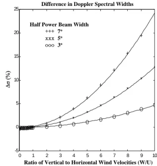
Fig. 8. Differences between spectral widths estimated from Doppler spectrum subject to horizontal wind in combination with vertical winds and a Gaussian beam broadening spectrum caused by hori-zontal wind only.
we find that 1σ is also a function of the ratio of vertical to horizontal wind speeds and their relationship can be well de-scribed by a parabolic equation expressed below as:
1σ = γ × (w/U )2(%), (22)
where γ values corresponding to θ1/23◦, 5◦and 7◦are, re-spectively, 0.0473, 0.1275 and 0.2423. Again, γ is related to θ1/2 by a power of 2 and can be expressed as γ =Gθ1/22 ,
688 Y.-H. Chu: Effects of along- and cross-radar-beam winds on Doppler radar spectrum 33 B A O' O P U U P' ZENITH NORTH EAST W Vr V E R D D’
Figure 9
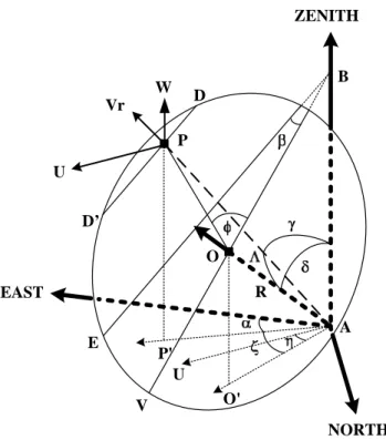
Fig. 9. Schematic configuration showing the geometric relations be-tween coordinate, pointing vector−→AOof an oblique antenna beam with zenith angle δ, horizontal U and vertical W wind vectors, and the angular position of selected point P on the cross section of the oblique antenna beam pattern, where the coordinate of the point P is defined by cone angles 3 and azimuth angles φ with respect to the boresight of oblique antenna beam. For details of the other symbols in the plot, see text.
where the magnitude of G is about 0.005 and θ1/2is in units of degree. From Eq. (22), we see that 1σ will increase dra-matically with the increases in w/U and θ1/2, suggesting that the vertical wind velocity effect on the width of the Doppler radar spectrum should be taken into consideration in the con-dition of large w/U and broad antenna beam. In adcon-dition, in light of a perfect agreement between the calculated data and the parabolic equation, as shown in Fig. 8, σm can be
achieved in terms of σBin accordance with Eq. (22) without
the use of the numerical integration to construct the corre-sponding beam broadening spectrum.
4 Transformation of wind velocity
Although the results obtained in Sects. 2 and 3 are based on the vertically pointed radar beam, we will show in this section that they can be applied to the oblique radar beam through the transformation of vertical and horizontal wind velocities into along- and cross-radar beam wind velocities defined on the cross section of oblique radar beam. Figure 9 presents a schematic diagram showing the geometry of the cross section of an oblique antenna beam with tilted angle δ at slant range R, in which −→AO is the pointing vector of the antenna beam axis, −→BV is the projection of the vector
−→
AOon the cross section of the oblique beam,−→AP is the vec-tor connecting antenna A and an arbitrary point P on the oblique cross section,−→BE is the intersection of the oblique plane and the vertical plane comprising the horizontal wind vector through vertical axis AB, DD0is the line through the point P parallel to−→BE, the angular coordinate of the selected point P is (3, φ) and 3 is called a cone angle relative to vec-tor−→AOand φ is termed as a clock angle with respect to axis −→
BV. Note that the vector−→AOis normal to the oblique plane at point O such that the plane is tilted with vertical axis at the angle of π /2−δ. Referring to Fig. 9, the radial velocity Vr at point P , subjected to a uniform background wind, can
be formulated as:
Vr=u ×cos α × sin γ + v × sin α × sin γ + w × cos γ
, (23)
where u and v are, respectively, the eastward and northward components of the horizontal wind, w is the vertical wind velocity, α is the angle between the axis toward due east and vector−AP−→0which is the projection of vector−→AP on horizon-tal plane, and γ is zenith angle of vector−→AP. Referring to Fig. 9, by introducing angles ζ and η, Eq. (23) can be ex-pressed below as:
Vr =Ucos(ζ − η) × sin γ + w × cos γ , (24)
where U (= √
u2+v2)is the horizontal wind velocity, η is the angle between horizontal wind vector and−AO−→0, and ζ is the angle betweenAO−−→0andAP−−→0, where O0 and P0 are, respec-tively, the projections of the points O and P on the ground. From Fig. 9, the following identities can be obtained:
cos γ = cos δ cos 3 + sin δ sin 3 cos φ, (25)
sin ζ sin γ = sin 3 sin φ, (26)
cos ζ sin γ = sin δ cos 3 − cos δ sin 3 cos φ, (27)
Substituting Eq. (25), Eq. (26), and Eq. (27) into Eq. (24), we have the radial velocity at point P as below:
Vr =Ucos η(sin δ cos 3 − cos δ sin 3 cos φ)
,
+Usin η sin 3 sin φ + w(cos δ cos 3 + sin δ sin 3 cos φ)
. (28)
To proceed, we decompose the total wind vector V , which is determined by the given wind vectors w and U , into two mutually orthogonal components V⊥ and V||, where V⊥ is
the component of V along the beam axis−→AOand is called an along-radar-beam wind and V||is the one lying on the oblique
plane and called a cross-radar-beam wind perpendicular to −→
AO. After tedious mathematical manipulation, Eq. (28) can be transformed into the following expression:
Vr=V||⊥sin(φ + β) sin 3 + V ||
||cos(φ + β) sin 3 + V⊥cos 3
, (29)
where φ is the clock angle of point P with respect to line −→
BV, β is the angle between−→BE and−→BV, V||⊥ and V||||are, respectively, the components of the cross-radar-beam wind
Y.-H. Chu: Effects of along- and cross-radar-beam winds on Doppler radar spectrum 689 V|| projected to the line CC0and to the line BB0. Note that
line CC0is the line parallel to−→BE through the point O on the oblique plane and line BB0is the one normal to CC0on the oblique plane, as shown in Fig. 10. The expressions of V||⊥and V||||can be formulated in terms of w, U , δ, β, and η as below
V||⊥=wsin δ sin β − U cos η cos δ sin β + U sin η cos β
, (30)
V||||=wsin δ cos β − U cos η cos δ cos β − U sin η sin β
, (31)
and the expression of V⊥can be expressed as
V⊥=Ucos η sin δ + w cos δ. (32)
Inspecting Eq. (30)−Eq. (32) shows that for the case of back-ground wind uniformly distributed in the resolution volume V||⊥, V||||and V⊥are independent of cone angle θ and azimuth
angle φ on the oblique plane. By introducing velocity V||and
angle 2, Eq. (29) can be further rewritten as:
Vr =V||cos 9 sin 3 + V⊥cos 3, (33)
where 9=φ+β−2, V||=
q
(V||⊥)2+(V||
||)2, and
2=tan−1(V||⊥/V||||). Obviously, Eq. (33), developed for the oblique radar beam, is exactly identical to Eq. (20) for the vertically directed radar beam, in which the cross-radar-beam wind V|| and the along-radar-beam wind V⊥on
the oblique plane are, respectively, equivalent to the horizon-tal wind U and the vertical wind w on the horizonhorizon-tal plane of a vertical radar beam, and 9 measured with respect to the line CC0on the oblique plane is equivalent to 8 defined
with respect to the horizontal wind direction on cross section of vertical radar beam. In light of the equivalence in the two, the theoretical results obtained in Sects. 2 and 3 in the condition of the vertically directed radar beam can be directly applied to the case of the oblique beam by simply substituting V⊥ and V|| on the oblique plane for w and U
on the horizontal plane, respectively. Inspecting expressions Eq. (30)−Eq. (33) implies that the behavior of the resultant Doppler spectrum will depend heavily on the direction and speed of the background wind and tilt angle of the radar beam. It follows that the changes in U , w and β will lead to the changes in the shape and width of the corresponding Doppler spectrum. Under the special conditions of 9=90◦ or V||=0, Vr will be governed by V⊥ only and the shape of
corresponding Doppler spectrum will be in the exponential form with exceedingly narrow spectral width defined by Eq. (17) or Eq. (18), in which w is replaced by V⊥. As a
result, for an oblique radar beam the asymmetrical Doppler spectrum with a tremendously narrow width (as small as a few cm s−1)may be expected, irrespective of the presence of a fairly large horizontal wind velocity. Obviously, in this case the Gaussian spectrum, as shown in Eq. (19), is inappropriate to model the spectrum and remarkable error in the estimation of spectral width in terms of σB will be
induced. B A O' O U U ZENITH NORTH EAST W V V|| ⊥ V || || V ⊥ || V B’ C’ C
Figure 10
Fig. 10. Geometric relations between the wind vectors w, U , V ,
V⊥, V||, V||⊥, and V||||, in which CC0 is the line through point O parallel to−→BEas shown in Fig. 9 and BB0is the one normal to CC0 on the oblique plane.
5 Discussion
One of the advantages of Doppler radar in remote sens-ing of the atmosphere is the capability of measursens-ing turbu-lence strength aloft. The information of turbuturbu-lence embed-ded in the radar returns from refractivity fluctuations can be retrieved either from backscattered power or from ob-served Doppler spectral width (Cohn, 1995). For the spec-tral width method, the uses of radar beams pointed vertically or obliquely are common in the Doppler radar community (Kurosaki et al., 1996; Nastrom and Eaton, 1997). With this method, the turbulence strength is estimated by removing the contributions of beam broadening, wind shear broaden-ing, and gravity wave broadening from the observed Doppler spectral width of the oblique beam in accordance with the following expression (Nastrom and Eaton, 1997)
σt2=σobs2 −σBeam+shear2 −σwave2 . (34) It is noteworthy that for the vertical radar beam, although shear and wave broadening effects can be reasonably ig-nored, the effect of specular reflection from thin layers in the illuminating volume should be considered for the radar
operating at VHF band (Rottger and Larsen, 1990).
Al-though Eq. (34) has been used extensively in the radar com-munity to remove non-turbulence broadening spectral width, a number of factors that may contribute significantly to ob-served Doppler spectral width are not included. For example, Chu (2002) shows that the horizontal wind direction relative
690 Y.-H. Chu: Effects of along- and cross-radar-beam winds on Doppler radar spectrum to the obliquely directed radar beam direction can cause an
estimation error in the beam broadening spectral width as large as more than 15%. Our results presented in Sects. 3 and 4 indicate that the ratio of w to U for vertical beam or the ratio of V⊥ to V|| for the oblique beam are the
cru-cial factors influencing the Doppler spectral width. Quan-titative computation reveals that for the vertical radar beam the spectral broadening induced by vertical and horizontal winds will be greater by 11% or more than beam broadening due to horizontal wind only, where 6◦radar beam width and U=1.25 m s−1and w=10 m s−1are assumed in the computa-tion. However, for an oblique radar beam with a tilt angle of 15◦and the same beam width and wind velocities, the for-mer will be substantially greater than the latter by more than 24%, where the assumption that the horizontal wind direc-tion is parallel to the azimuth angle of the antenna beam axis is made. This result strongly suggests that the effects of per-pendicular wind V⊥for the oblique beam (or vertical wind
velocity for the vertical beam) on the beam broadening spec-tral width should be taken into consideration for the accu-rate retrieval of the turbulence parameter from the observed Doppler spectral width.
Radar experiments conducted at VHF band indicate that it is not uncommon that the observed Doppler spectral width for an oblique beam is less than the combination of the beam broadening, shear broadening and gravity wave broadening (Nastrom, 1997; Nastrom and Eaton, 1997). One of the causes for this phenomenon is attributed to the vertical vari-ation of the horizontal wind velocity in the illuminating vol-ume. Nastrom (1997) shows that vertical wind shear with a positive sign (i.e. horizontal wind velocity increases with height) will result in a negative contribution to the tral broadening, leading to the reduction of Doppler spec-tral width. However, for a uniform background wind (i.e. no wind shear effect), the theoretical results presented in Sects. 3 and 4 predict that the beam broadening spectrum with a tremendously narrow width can occur under the con-ditions of 9=90◦, or δ=90◦together with η=0 and w=0, or 0=δ, in combination with η=β=0, where 0 is defined as cot−1(w/U ). In these cases, the contribution of the cross-radar-beam wind V|| to radial velocity V r will vanish. As
a result, the corresponding Doppler spectrum will be gov-erned by the along-radar-beam wind V⊥in accordance with
Eq. (12) and a tremendously narrow spectral width is then expected.
In addition to the clear-air turbulence strength, the theory developed in the article may also apply to the precipitation Doppler spectrum observed by obliquely directed Doppler radar. Note that the falling velocity (or Doppler velocity) of a raindrop is the combination of its terminal velocity and ver-tical wind velocity, and the maximum terminal velocity of a raindrop can be as large as about 10 m s−1(Spilhous, 1948; Gunn and Kinser, 1949; Atlas et al., 1973). Consequently, the falling velocity of raindrop may be much greater than 10 m s−1, if the raindrop size is large and the downward ver-tical wind velocity is intense (Rao et al., 1999). According to the results obtained in Sects. 3 and 4, for the raindrop with a
large ratio of falling velocity to horizontal wind velocity ob-served by a vertical or oblique radar beam, the corresponding precipitation Doppler spectrum will have the breadth greater than that of the conventional Gaussian spectrum broadened by horizontal wind only. As a result, the raindrop distri-bution will be overestimated if the contridistri-bution of the large falling velocity of the raindrop to the beam broadening spec-tral width is not considered and only the conventional beam broadening spectral width σB is removed from the observed
precipitation Doppler spectrum. Therefore, a more complete algorithm is required to develop the estimation of more ac-curate precipitation information from the observed precipi-tation Doppler spectrum under the conditions of heavy rain and a weak horizontal wind.
The asymmetrical behavior of the beam broadening spec-trum induced by an along-radar-beam wind may also be one of the influential factors responsible for the skewness of type 1 radar spectra in the ionospheric sporadic-E (Es) region in the height range between 90 km and 150 km. The electron density irregularities responsible for the Es type 1 radar spec-tra are excited through a two-stream instability and propagate in the direction perpendicular to the magnetic field line (Far-ley, 1963). Coherent VHF radar has long been shown to be able to effectively detect the echoes from type 1 irregulari-ties by steering the radar beam perpendicular to the magnetic field line (e.g. Kelley, 1989). Es type 1 radar spectra are char-acterized by a relatively narrow spectral width compared to a fairly large mean Doppler velocity nominally at the speed of an ion-acoustic wave. It is well known that the ion-acoustic wave velocity in the Es region ranges from about 250 to 360 m s−1, depending on the latitude and height where type 1 irregularities are generated (e.g. Fejer and Kelley, 1980; Haldoupis et al., 1997). Apparently, exceedingly large drift velocity of type 1 irregularities along the radar beam will not only broaden the width of type 1 radar spectra, but also sig-nificantly influence the shape of the radar spectra, producing an asymmetrical shape of the spectra. Although an effec-tive antenna beam pattern (defined as the product of antenna beam pattern and aspect sensitivity) for the measurement of field-aligned Es irregularities is fan-like (i.e. very narrow in elevation and fairly wide in azimuth direction) (Chu and Wang, 1999, Chu and Wang, 2002), the results obtained in this article are still applicable to Es type 1 radar spectra by replacing the original antenna pattern with an effective an-tenna pattern in Eq. (1), provided that the irregularities fill in the expected echoing region. A detailed discussion on this subject will be given in another paper. In fact, a wealth of ob-servational evidences obtained by various radar experiments show that the radar spectra of type 1 irregularities indeed ex-hibit a one-sided low frequency wing (e.g. Fejer et al., 1975; Schlegel and Haldoupis, 1994; Chu and Wang, 2002). This kind of asymmetrical shape of the radar spectrum seems to be consistent with that of the example of the spectrum shown in Fig. 6. Therefore, in combination with horizontal drift of the electron density irregularities, the beam broadening ef-fect due to an exceedingly large velocity of the electron den-sity irregularities drifting along the radar beam axis may be
a plausible cause for the explanation of the asymmetry of Es type 1 radar spectra.
6 Conclusion
The analytical expression of beam broadening spectrum for the vertical radar beam induced by vertical wind in the ab-sence of a horizontal wind is derived in this article and its spectral shape is found to be in exponential form. The differ-ence between the mean Doppler velocity of the exponential spectrum and the true vertical wind velocity is the function of the antenna beam width only, while its spectral width is pro-portional to the product of the vertical wind velocity and the square of the radar half-power beam width. The character-istics of the beam broadening spectrum induced by vertical wind in combination with horizontal winds for the vertical beam are also investigated in this article by using a numerical simulation method, which is very difficult to obtain analyti-cally due to the curved nature of the radial velocity contour. The results reveal that the difference between the mean radial velocity of the beam broadening spectrum and the true ver-tical wind velocity as a function of the ratio w/U is very small, generally less than 0.6% for the typical condition. However, its spectral width is greater than that calculated from the modeled Gaussian spectrum broadened by a hori-zontal wind only, by 15% for the typical case. Moreover, by employing an empirical parabolic equation proposed in this article, the width of the beam broadening spectrum broad-ened by the vertical and horizontal winds can be estimated in terms of the beam broadening spectral width caused by the horizontal wind only, without numerically constructing the beam broadening spectrum by integrating the radar power along the curved contour of the radial velocity. A transfor-mation of the vertical and horizontal wind velocities into an along-radar-beam wind V⊥ and cross-radar-beam wind
ve-locities V||for an obliquely directed radar beam is developed
in this article. One of the advantages of this transformation is that, by incorporating the beam broadening spectral width induced by the horizontal wind, the beam broadening spec-tral width for the oblique radar beam, under the condition that the contour of the Doppler velocity on the cross section of the radar beam is curved and very difficult to be modeled by mathematical equation, can be computed in accordance with Eq. (22) by simply replacing w and U with V⊥and V||
defined on an oblique plane, respectively. With the wind ve-locity transformation, under a special condition the oblique Doppler spectrum with exceedingly narrow width (smaller than a few cm s−1)is expected, irrespective of the presence of a large horizontal wind velocity and broad antenna beam width.
Acknowledgements. I would like to thank Hoppe, U.-P. and one
of the anonym referees for their helpful and constructive sugges-tions on this paper. This work was partially supported by National Science Council of the Republic of China (Taiwan) under grant NSC93-2111-M-008-025-AP3 and National Space Program Office under the grant 93-NSPO(B)-RS3-FA07-01.
Topical Editor U.-P. Hoppe thanks two referees for their help in evaluating this paper.
References
Atlas, D., Srivastava, R. C., and Sekhon, R. S.: Doppler radar char-acteristics of precipitation at vertical incidence, Rev. Geophys. Space. Sci., 11, 1–35, 1973.
Battan, L. J. and Theiss, J. B.: Observations of vertical motions and particle sizes in a thunderstorm, J. Atmos. Sci., 23, 78–87, 1966. Brandes, E. A., Vivekanandan, J., Tuttle, J. D., and Kessinger, C. J.: A study of thunderstorm microphysics with multiparameter radar and aircraft observations, Mon. Wea. Rev., 123, 3129– 3143, 1995.
Chu, Y. H.: Beam broadening effect on oblique MST radar Doppler spectrum, J. Atmos. Oceanic Technol., 19, 1955–1967, 2002. Chu, Y. H., Chao, J. K., Liu, C. H., and R¨ottger, J.: Aspect
sen-sitivity at tropospheric height measured with vertically pointed antenna beam of the Chung-Li VHF rada, Radio Sci., 25, 539– 550, 1990.
Chu, Y. H. and Wang, C. Y.: Interferometry investigations of VHF backscatter from plasma irregularity patches in the nighttime E region using the Chung-Li radar, J. Geophys. Res., 104, 2621– 2631, 1999.
Chu, Y. H. and Wang, C. Y.: Three-dimensional Spatial Struc-tures of Mid-Latitude Type 1 Es Irregularities, J. Geophys. Res., 107(A8), 10.1029/2001JA000215, 2002. 2002.
Cohn, S. A.: Radar measurements of turbulent eddy dissipation rate in the troposphere: A comparison of technique, J. Atmos. Oceanic Technol., 12, 85–95, 1995.
Farley, D. T.: A plasma instability resulting in field-aligned irreg-ularities in the ionosphere, J. Geophys. Res., 68, 6083–6094, 1963.
Fejer, B. G. and Kelley, M. C.: Ionospheric Irregularities, Rev. Geo-phys., 18, 401–454, 1980.
Fejer, B. G., Farley, D. T., Balsley, B. B., and Woodman, R. F.: Oblique VHF radar spectral studies of the equatorial electrojet, J. Geophys. Res., 80, 1307–1312, 1975.
Gunn, R. and Kinser, G. D.: The terminal velocity of fall for water droplets in stagnant air, J. Meteor., 6, 243–248, 1949.
Haldoupis C., Farley, D. T., and Schlegel, K.: Type-1 echoes from the mid-latitude E-region ionosphere, Ann. Geophys., 15, 908– 917, 1997,
SRef-ID: 1432-0576/ag/1997-15-908.
Hocking, W. K.: On the extraction of atmospheric turbulence pa-rameters from radar backscatter Doppler spectra – Theory, J. At-mos. Terr. Phys., 45, 89–102, 1983.
Hocking, W. K.: Observation and measurement of turbulence in the middle atmospfere with a VHF radar, J. Atmos. Terr. Phys., 48, 656–670, 1986.
Kelley, M. C.: The earth’s ionosphere, Academic Press, San Diego, California, 1989.
Kurosaki, S., Yamanaka, M. D., Hashiguchi, H., Sato, T., and Fukao, S.: Vertical eddy diffusivity in the lower and middle at-mosphere: a climatology based on the MU radar observations during 1986–1992, J. Atmos. Terr. Phys., 58, 727–734, 1996. Nelson, S. P.: The influence of storm flow structure on hail growth,
J. Atmos. Sci., 40, 1965–1983, 1983.
Nastrom, G. D.: Doppler radar spectral width broadening due to beamwidth and wind shear, Ann. Geophys., 15, 786–796, 1997, SRef-ID: 1432-0576/ag/1997-15-786.
692 Y.-H. Chu: Effects of along- and cross-radar-beam winds on Doppler radar spectrum
Nastrom, G. D., and Eaton, F. D.: Turbulence eddy dissipation rates from radar observations at 5–20 km at White Sands Mis-sile Range, New Mexico, J. Geophys. Res., 102, 19 495–19 505, 1997.
Rao, T. N., Rao, D. N., and Raghavan, S.: Tropical precipitating systems observed with Indian MST radar, Radio Sci., 34, 1125– 1139, 1999.
Rottger, J. and Larsen, M. F.: UHF/VHF radar techniques for atmo-spheric research and wind profiler applications, in Radar in Me-teorology, edited by David Atlas, Am. Meteorol. Soc., Boston, Mass., 235–281, 1990.
Schlegel, K. and Haldoupis, C.: Observation of the modified two-stream plasma instability in the midlatitude E region ionosphere, J. Geophys. Res., 99, 6219–6225, 1994.
Sloss, P. W. and Atlas, D.: Wind shear and reflectivity gradient ef-fect on Doppler radar spectra, J. Atmos. Sci., 25, 1080–1089, 1968.
Spilhous, A. F.: Raindrop size, shape, and falling speed, J. Meteor., 5, 108–110, 1948
Wakasugi, K., Mizutani, A., Masaru, M., Fukao, S., and Kato, S.: A direct method for deriving drop-size distribution and vertical air velocities from VHF doppler radar spectra, J. Atmos. Oceanic Technol., 3, 623–629, 1986.
Woodman, R. F. and Chu, Y. H.: Aspect Sensitivity measurements of VHF backscatter made with Chung-Li radar: Plausible mech-anisms, Radio Sci., 4, 113–125, 1989.
Wang, C. Y. and Chu, Y. H.: Investigations of Blob-like Sporadic E Plasma Irregularities Using the Chung-Li VHF Radar, J. Atmos. Solar-Terr. Phys., 63, 123–13, 2001.
Ziegler, C. L., Ray, P. S., and Knight, N. C.: Hail growth in an Oklahoma multicell storm, J. Atmos. Sci., 40, 1768–1791, 1983.