Design of a Microreactor for Studying the Effect of
Shear Stress on Angiogenesis in Self-Assembling
Peptide Matrix
by Jennifer T. Blundo S.B. Mechanical Engineering S.B. Management Science MIT, 2002SUBMITTED TO THE DEPARTMENT OF MECHANICAL ENGINEERING IN PARTIAL FULFILLMENT OF THE REQUIREMENTS FOR THE DEGREE OF
MASTER OF SCIENCE IN MECHANICAL ENGINEERING AT THE
MASSACHUSETTS INSTITUTE OF TECHNOLOGY JUNE 2004
C2004 Jennifer T. Blundo. All rights reserved.
The author hereby grants to MIT permission to reproduce and to distribute publicly paper and electronic copies of this thesis document in whole or in part.
Signature of Author...
QirartmenfMva(anical
Engineering May 7, 2004 C ertified by ... ....r---.--.----..--.-.-.-.---Roger D. Kamm Professor of Mechanical Engineering and Biological Engineering Thesis Supervisor Certified by ...
Accepted by ...
MASSACHUSETTS INS E OF TECHNOLOGY
r
/ifz
Jeffrey T. Borenstein The Charles Stark Draper Laboratory Thesis SupervisorAin Sonin Professor of Mechanical Engineering Chairman, Committee for Graduate Students
Design of a Microreactor for Studying the Effect of
Shear Stress on Angiogenesis in Self-Assembling
Peptide Matrix
by
Jennifer T. Blundo
Submitted to the Department of Mechanical Engineering on May 7, 2004 in
Partial Fulfillment of the Requirements for the Degree of Master of Science
in Mechanical Engineering
Abstract
Understanding blood vessel formation has become a principal, yet challenging, objective of bioengineering over the last decade. Unraveling the complex mechanisms of angiogenesis could lead to the development of pro or anti-angiogenic treatments for diseases like heart disease and cancer, as well as to the development of viable scaffolds for tissue engineering and biosensors.
In pursuit of an optimal in vitro model to study angiogenesis, the aim of this thesis is to design and fabricate a microscale bioreactor to study the effect of shear stress on angiogenesis using a microfabricated substrate, a self-assembling peptide gel, and bovine aortic endothelial cells. A theoretical model was developed to approximate the permeability of the peptide gel and to quantify the average shear stress on an endothelial cell seeded in a 3D matrix of the peptide gel. Experimental results in a macroscale system demonstrate endothelial cell lumen formation and elongation in the direction of interstitial flow in response to physiological levels of shear stress ~ 10 dynes/cm2, as well
as increased cell viability; negligible shear control samples demonstrate no lumen formations and lower cell density.
In order to gain more insight on the complex mechanisms of angiogenesis, the proposed microscale device closely mimics in vivo conditions and allows for real time imaging and monitoring of endothelial cell migration and network formation. The device has the potential to investigate the synergistic effects of mechanical and biological factors, including varying levels of shear stress and the delivery of chemoattractants or angiogenic factors. The experimental setup incorporated optimizing the geometry of the microfluidic channels, the protocols for cell imaging, and the techniques for forming peptide gel in the device. The results of experiments with the peptide gel and endothelial cells in the device exhibit promising scaffolds for regions of 3D cell culture under interstitial flow.
Thesis Co-Supervisor: Roger D. Kamm
Title: Professor of Mechanical Engineering and Biological Engineering Thesis Co-Supervisor: Jeffrey T. Borenstein
Acknowledgements
I would like to thank my thesis advisors, Roger Kamm and Jeff Borenstein for their guidance and supervision in the completion of this project, and most importantly, for inspiring me to pursue biomedical research endeavors. Particular thanks to my
research colleagues, Daria Narmoneva and Suelin Chen, who were important contributors to the macroscale experimental and cell culture work.
At Draper Laboratory, I would like to thank everyone in the MEMS groups who helped to facilitate the design and fabrication of the microfluidic devices, including Brian
Orrick, Ed Barnard, Issac Costa, and Dick Caruso.
Additionally, thanks to my fellow labmates, Eli, Mo, Gina, Pete, and Jorge for their help and friendship through our many lab adventures.
Finally, I would like to acknowledge and thank my family for their love and support during my tenure at MIT and in all aspects of my life.
This graduate work was supported in part by a National Science Foundation Graduate Fellowship and by a Charles Stark Draper Fellowship.
List of Contents
A bstract ...
3
A
cknow ledgem ents...
5
L ist of C ontents...
7
List of Figures...
11
List of Tables...
13
1. Introduction...
15
1.1. Background... 15 1.1.1. Tissue Engineering ... 15 1.1.2. Angiogenesis... 171.1.3. In vitro Cell Culture M odels... 21
1.2. Enabling Technologies... 24
1.2.1. Self-Assembling Oligopeptide... 24
1.2.2. Soft Lithography M icrofluidics ... 28
1.3. Objective and Aim s... 30
1.3.1. Specific Aim 1: M acroscale Bioreactor Studies ... 31
1.3.2. Specific Aim 2: Design of Microscale Bioreactor... 32
1.3.3. Specific Aim 3: Validation of Microscale Bioreactor ... 32
1.4. Sum m ary...33
2. M acroscale B ioreactor...
35
2.1. Introduction... 35 2.2. Bioreactor Design ... 35 2.3. Flow Properties ... 38 2.3.1. Oxygen Transport ... 38 2.3.2. Diffusion Analysis ... 39 2.3.3. Shear Stress... 402.4. Biological M aterials & M ethods... 41
2.4.1. Self- Assembling Peptide Gel... 42
2.4.2. Cell Culture... 42
2.5. Bioreactor M aterials & M ethods ... 43
2.5.1. Peptide Scaffold ... 43
2.5.2. Flow Delivery ... 44
2.6. Device Validation ... 46
3. M icroscale B ioreactor ...
47
3.1. Introduction... 47
3.2. Design Objectives ... 49
3.2.1. M acroscale Bioreactor M otivations... 50
3.2.2. M icroreactor Design Specifications... 51
3.3. Flow System Design ... 52
3.4. Flow Properties ... 55
3.4.1. Oxygen Transport ... 55
3.4.2. Diffusion Analysis ... 55
3.4.3. Flow Analysis ... 56
3.5. Device Design: M icrofabrication... 58
3.5.1. M ask design... 58
3.5.2. Silicon W afer Fabrication... 59
3.5.3. PDM S Casting ... 60
3.5.4. Plasm a Bonding ... 61
3.6. Device Design: M acroscale ... 63
3.6.1. Fluidic Fittings ... 63
3.6.2. Stage Design ... 64
3.6.3. Fluid Reservoirs & M ounts... 66
3.7. Biological M aterials & M ethods ... 67
3.7.1. Cell Culture... 67
3.7.2. Self-A ssem bling Peptide... 67
3.8. M aterials & M ethods: M icroreactor Assembly ... 68
3.9. Device Validation ... 69
3.10. Sum m ary ... 72
4. T heory ... 75
4.1. Introduction... 75
4.2. Perm eability of the Peptide Gel... 75
4.3. Flow Through Peptide Gel... 83
4.4. Flow Past a Single Endothelial Cell... 85
4.5. Shear Stress on Endothelial Cell... 93
4.6. Sum m ary ... 96
5.
Experimental Studies& Results...99
5.1. Introduction... 99
5.2. Perm eability of Peptide Gel... 99
5.2.1. M aterials and M ethods... 100
5.2.2. Results... 101
5.2.3. Discussion... 104
5.3. M acroscale Bioreactor Experim ents ... 109
5.3.1. M aterials and M ethods... 109
5.3.2. Results: 2D Im ages ... 110
5.3.3. Results: 3D Im aging ... 112
5.4. M icroreactor Experiments ... 116
5.4.1. M ethods and M aterials... 117
5.4.2. Geometric Optimization... 117
5.4.3. Self-Assembling Peptide: Fluorescent M icrobeads ... 121
5.4.4. Collagen w/ Fluorescent Beads... 125
5.4.5. Peptide and Cells... 127
5 .5 . D iscu ssion ... 130
6. Recom m endations...133
6.1. Design of In Vitro Cell Culture Devices... 133
6.2. Design of Self-Assembling Peptide Gel Scaffolds ... 133
6.2.1. Permeability ... 133
6 .2 .2 . S tiffness... 134
6.3. Theoretical and Experimental Modeling of Angiogenesis ... 135
7.
Conclusions...137
7.1. Summary of W ork... 137
7 .2 . R esu lts... 13 7 7.3. Recommendations for Future W ork... 139
References...141
Appendix...147
A. 1. Preliminary Data Endothelial Cell 2D Cultures in Peptide Gel... 147
A.2. Endothelial Cell Viability in pH-Adjusted M edia ... 150
List of Figures
Figure 1.1. D iagram of capillary bed [6] ... 18
Figure 1.2. Typical capillary structure ... 19
Figure 1.3. Processes of blood vessel growth [9] ... 20
Figure 1.4. Mechanisms of angiogenesis [9]... 21
Figure 1.5. Chemical and molecular structure of RADA16-II ... 25
Figure 1.6. SEM im age of peptide gel [48] ... 26
Figure 1.7. Peptide gel promotes network formation ... 27
Figure 1.8. Parallel-plate flow chamber [52]... 29
Figure 2.1. Solidm odel of bioreactor ... 36
Figure 2.2. Cross sectional view of 2D seeding experiment in bioreactor ... 37
Figure 2.3. Cross sectional view of 3D experiment in bioreactor ... 38
Figure 2.4. Flow diagram for bioreactor experiment... 45
Figure 3.1. Solid model of assembled microfluidic device ... 48
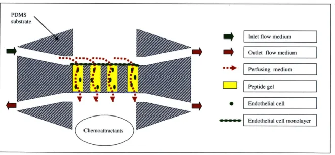
Figure 3.2. Proposed angiogenesis experiment in microreactor ... 49
Figure 3.3. Schematic of microfluidic channels ... 53
Figure 3.4. Flow protocol for filling the microfluidic channels ... 54
Figure 3.5. Design and layout of soft lithography mask... 59
Figure 3.6. Diagram of the silicon photolithography process... 60
Figure 3.7. Microfluidic channel assembly by plasma bonding ... 62
Figure 3.8. Fluidic fittings and optics dish assembly... 63
Figure 3.9. Solid model of platform for microreactor ... 65
Figure 3.10. Sequence and molecular structure of RADA 16-I... 68
Figure 3.11. Experimental setup of microreactor on microscope stage... 69
Figure 3.12. Flow diagram for microreactor validation... 70
Figure 3.13. Air bubbles initially block microfluidic channels ... 71
Figure 4.1. Bilayer structure of an assembled RADA 16-I P-sheet ... 78
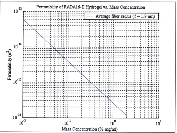
Figure 4.2. Log-log plot of permeability of RADA16-II gel vs. mass concentration... 79
Figure 4.3. Permeability of RADA 16-Il gel vs. mass concentration for various fiber radii ... 8 1 Figure 4.4. Interstitial flow through peptide scaffold ... 83
Figure 4.5. Diagram of flow past single endothelial cell in porous matrix ... 86
Figure 4.6. Pressure field around an endothelial cell in peptide gel... 92
Figure 4.7. Contour plot radial velocity field around an endothelial cell in peptide gel. 92 Figure 4.8. Dimensionless shear stress on the surface of an endothelial cell... 93
Figure 4.9. Average dimensionless shear stress on endothelial cell vs. volume fraction 95 Figure 5.1. Experimental setup for measuring permeability of the peptide gel... 101
Figure 5.2. Average permeability of 1% RADA16-II gel vs. time, dataset 1... 103
Figure 5.3. Average permeability of 1% RADA 16-II gel vs. time, dataset 2... 104
Figure 5.4. Shear stress on surface of an endothelial cell for theoretical and experimental values of permeability of 1% RADA 16-II gel... 107
Figure 5.5. 2D images of lumen formation in direction of flow... 111 Figure 5.6. MIP image of 3D reconstruction of endothelial cells in 1% RADA 16-II
Figure 5.7. 3D image reconstruction of endothelial cells in 1% RADA 16-11 scaffold . 114 Figure 5.8. Magnified 3D reconstruction of lumen formation in 1% RADA 16-11 scaffold
1 15r Figure 5.9. Geom etry of m icrofluidic channels ...
Figure 5.10. Flow diagram 1 for peptide gel experiments... Figure 5.11. Filling, clearing, and gelling of peptide solution in three microfluidic
ch an n e ls... Figure 5.12. Flow diagram 2 for peptide gel experiments... Figure 5.13. Filling, clearing, and gelling of peptide solution in all five channels ... Figure 5.14. Collagen gel in microfluidic channels... Figure 5.15. Flow diagram of setup of cell culture experiment... Figure 5.16. Flow diagram of media delivery for cell culture experiment ... Figure 5.17. Image of endothelial cells in peptide gel channel ...
118 122 123 124 125 126 127 129 130
Figure A. 1.1. Peptide gel promotes proliferation and limits apoptosis. ... 147
Figure A. 1.2. Peptide gel promotes cell survival in 3D-embedding, collagen I gel causes w idespread apoptosis. ... 147
Figure A. 1.3. Peptide gel promotes lumen formation... 148
Figure A. 1.4. Peptide gel enhances VEGF expression. ... 148
Figure A. 1.5. Endothelial cell networks form more quickly on more compliant gel.... 149
Figure A.2. 1. Endothelial cell viability in pH-adjusted media vs. time... 150
Figure A.3.1. Microreactor platform base ... 151
Figure A.3.2. Top & bottom valve mounts for vertical channel... 151
Figure A.3.3. Inlet valve mount horizontal channels... 152
List of Tables
Table 3.1. Product contract for design of microreactor ... 52
Table 3.2. Dimensions of cell culture regions and microfluidic channels... 53
Table 3.3. Resistance of microfluidic delivery channels ... 57
Table 4.1. Theoretical estimates of volume fraction and permeability of peptide gel for various m ass concentrations ... 82
Table 5.1. Experimental parameters and flow properties for calculating permeability of 1% R A D A 16-II gel ... 102
Table 5.2. Statistical averages for permeability data of 1% RADA 16-II gel ... 105
Table 5.3. Comparison of average and max shear stress on surface of an endothelial cell for theoretical and experimental permeability of 1% RADA 16-II gel ... 107
Table 5.4. Dimensions and geometry of microfluidic channel design: version 1... 119
Table 5.5. Dimensions and geometry of microfluidic channel design: version 2... 120
Table 5.6. Dimensions and geometry of microfluidic channel design: version 3... 121
1.
Introduction
1.1. Background
1.1.1. Tissue Engineering
Tissue engineering is the construction, repair, or replacement of damaged or diseased tissue [1]. The development of this field is spurred by the staggering numbers of patients that suffer from tissue loss or end-stage organ failure every year. The goal of tissue engineering is to merge the technologies of biology and engineering to deliver viable treatment options for patients diagnosed with dehabilitating or life-threatening conditions, like cardiovascular disease which is the leading cause of morbidity and mortality in industrialized countries around the world [2]. Recent advances in cellular and molecular biology, biomaterials, and the integration of biology and materials to deliver viable cells in a compatible structure have resulted in many rapid advances in tissue engineering [3].
One of the major challenges facing the tissue engineering field is the research and development of treatments that can reach a widespread number of patients. There are two approaches to tissue engineering research models: in vivo systems and in vitro systems. In vivo models are the most accurate at representing cellular behavior in a natural biological environment; however, in vivo models are often animal-based studies, which can be costly as well as hard to engineer. A large number of variables exist in animal studies that may difficult to control and/or quantify, so these models may not amenable for studies at the level of individual cellular behavior. In vitro models present a
microscale. The aim of in vitro models is to recreate the in vivo microenvironment by regulating physiological factors, such as nutrients and growth factors and mechanical factors, such as flow or cyclic conditioning. The development of in vitro models, such as bioreactors has proved a valuable system for studying the complex mechanisms of many cellular processes. Additionally, in vitro models have expanded to include the design and development of biological scaffolds that are optimal for tissue engineering applications.
On a structural level, the primary function of a tissue engineering scaffold is to provide a supportive framework for seeding and culturing cells, however, a scaffold has the potential to serve functions at both the biological and mechanical level. Scaffolds can be made up of natural materials, synthetically designed materials, or even a combination of both. Natural materials from the body, such as collagen are an appealing choice. In addition to their immunogenic desirability, these materials already contain information or cues, such as certain amino acid sequences, which facilitate cell attachment or maintenance of differentiated function [1]. One drawback to the selection of natural materials for scaffolds is that their mechanical properties are poorly defined and in addition, there are batch-to-batch variations and scale-up difficulties [4]. In order to design an optimal scaffold, research efforts have focused on fabricating synthetic biomaterials. By design, these biomaterials allow precise control over properties such as molecular weight, degradation time, hydrophobicity, mechanical stiffness, and cellular cues.
Many biomaterials have been considered for use as biological scaffolds, including collagen gels, fibrin gels, and Matrigel, but most fall short of meeting all the necessary specifications. These criteria include 1) lack of cytotoxicity; 2) minimal
immunogenicity; 3) controlled and predictable biodegradation rate; 4) chemical compatibility with physiological conditions; 5) simple and scalable production; 6) ability of the materials properties to be modified. In particular, current scaffolds for vasculature experiments, such as Matrigel or collagen require the addition of external angiogenic factors for network formation and cell survival [5]. In particular to cardiovascular tissue engineering, one of the key properties of a biological scaffold is to promote angiogenesis and tissue revascularization [4].
Once a tissue engineered construct is successfully grown in vitro, it must be transplanted into the patient and incorporated into the existing vascular network and organ system. Understanding the complexity of the microvasculature and underlying tissues is a continued challenge for tissue engineering researchers, both at the fundamental level of capillary network formation and at the systematic level of cardiac heart failure. Research on the genomic and mechanical properties of endothelial cells, which line all the blood vessels in the body, has provided intriguing clues about the structure and function of the cardiovascular system on a cellular level. In order to design organ specific tissue replacements, studies at the cellular level and experimental models that enable these discoveries will be an important part of advances in tissue engineering research.
1.1.2. Angiogenesis
The first step to engineering new or replacement tissue is understanding the formation and structure of the microvasculature, which is the backbone of all tissues. Capillaries are the smallest branches of the vascular tree and are the sites of oxygen and
these branches is indicated by the fact that all tissue cells are located within a distance of only 60-80 [tm of a capillary. A typical capillary bed is depicted in Figure 1.1.
Metarteriole
f
Preferential channelArteriale Precapillary
sphincter
e-.%%,,True copillaries'
Venule
Figure 1.1. Diagram of capillary bed [6]
Unlike the vessels of the arterial and venous systems, the walls of capillaries are very thin and are composed of only one cell layer-a simple squamous epithelium called the endothelium. Capillaries are so small that red blood cells can only pass through in single file. The average capillary diameter measures 5 - 10 gm and the average length is 1mm. Figure 1.2 is a cross-sectional view the structure of a typical capillary, however, depending on the location in the vascular tree, the structure of the endothelium will differ.
Figure 1.2. Typical capillary structure
Angiogenesis is the formation or "sprouting" of new capillaries by migration and proliferation of endothelial cells. Angiogenesis plays a critical role in organ development and differentiation during embryogenesis and in adults as a part of physiological processes like wound healing [7]. In addition, deregulated angiogenesis has been implicated in the pathogenesis of numerous diseases including vascular retinopathies, rheumatoid arthritis, and cancer [8]. Therefore, understanding blood vessel formation has become a principal, yet challenging, objective of bioengineering over the last decade. Unraveling the mechanisms of angiogenesis would offer therapeutic options to ameliorate or perhaps even cure disorders like heart disease and cancer that are leading causes of mortality as well as spur the development of viable scaffolds for tissue engineering and biosensors [9].
Angiogenesis is a series of complex steps. First, endothelial cells loosen their intercellular junctions and begin degradation of the surrounding pericellular matrix. After a path has been cleared, proliferating endothelial cells migrate toward the source of the angiogenic stimulus, resulting in the formation of sprouts and lumen. Once the
Nucleus Endothelial
Cell
sprouts join to form capillary-like structures, endothelial cells arrest proliferation, synthesize a new basement membrane, and stabilize [9].
EMBRVO iprising muhr brwIds*, iiessuiwrep(Iea
0
i**2WtOeei
%RG3. NA A M . i iC-a 'r.AmiR, % ~S"iJftZ Remoadil-g (brahlCuA. Ig idduiVE fGF aGI. Am. IbZ
Figure 1.3. Processes of blood vessel growth [9]
The growth of new capillaries is tightly controlled by an interplay of growth regulatory proteins, which either act to stimulate or inhibit blood vessel growth [10]. In particular, vascular endothelial growth factor (VEGF) has been identified as an essential regulator in early vasculature development [11].
I ' iflletVss 00 MIM3.Ago st. he M .M 2 I Afweriegvmas qwroutlmg ,eaturatiuu kooviediaal aW gradw EL
nK LK rwax4 virru;~s 31-I ~13.. N %'pI
tehoois wh~ichw4 lb ritaufor eveopn tsse-ninerngtetmns
E C diffemra. tunl-AL qahmet .prrmashrh. baakr. icactiu~
Figure 1.4. Mechanisms of angiogenesis [9]
Furthermore, external factors, such as the extracellular matrix, shear stress, and hypoxia have been shown play key angiogenic roles [9, 12, 13].
1.1.3. In vitro Cell Culture Models
The World Technology Panel Report 2002 identified a number of emerging technologies, which will be critical for developing tissue-engineering treatments. Specifically, bioreactor design and the development of novel systems for the expansion of a variety of cell types and sources, both in 2D and 3D culture were highlighted [14].
In vitro bioreactors have been developed for studies many types of cells, such as
The development of in vitro models is an active and promising approach for identifying factors involved in angiogenesis [18-22]. In vitro angiogenesis models
recapitulate in vivo processes in several capacities. In vitro models mimic in vivo
architecture as well reproduce cell differentiation, proliferation, migration and the network formation steps of angiogenesis. The results of in vitro studies can be characterized in terms of morphological responses, such as cell shape and orientation as well as functional responses, such as cell-cell signaling and migration.
The most recent in vitro studies of angiogenesis have focused on two-dimensional (2D) and three-dimensional (3D) models. Selecting the appropriate experimental model for angiogenesis is important because studies have shown that cell behavior in 3D cultures is completely different from behavior 2D cultures [23].
Two-dimensional model for cell cultures are older, simpler, and thus better characterized than 3D models. A typical 2D system consists of a monolayer of endothelial cells on the surface of a culture plate [20, 24-26] or on the surface of a gel [27-29]. Matrigel has been the most successful 2D substrate because of its reproducibility and consistency; however, researchers have experimented with a variety of substrate materials including gelatin, fibronectin, collagen, and amnionic membrane [30].
2D systems are considered effective for characterizing the less complex aspects of angiogenesis, such as the role of the extracellular matrix (ECM) in vascular morphogenesis and intussusceptive sprouting [30]. While these models replicate the endothelial monolayer in vivo and the attachment to the basement membrane, once the angiogenic process begins in vivo, the basement membrane degrades and the endothelial
cells migrate into the ECM, introducing a third dimension that 2D monolayer models lack. This information suggests the results of 2D models of angiogenesis are inadequate and possibly misleading.
3D configurations are more sophisticated than 2D systems and allow for better assessment of the complex mechanisms of angiogenesis, such as cell migration, cell proliferation and apoptosis [21, 31], the role of cytokines (Pepper et al, 1994), the diffusion of soluble factors [19], the role of cell adhesion molecules [32, 33], the mechanisms of tubulogenesis [34, 35], and the mechanical forces exerted on the ECM [36]. The chemotaxis of endothelial cells induced by the gradient of diffusion of oxygen, nutrients, and soluble factors is also easier to investigate in a 3D model.
Endothelial cell response in large arteries and the atheroprotective effects of physiological levels of shear stress have been studied extensively [37-39]. While the results of these studies have significant implications for the pathogenesis of arteriosclerosis [40], little work has focused on endothelial response in an interstitial environment. While 3D models are more complex than 2D models, and thus more difficult to control than a 2D system, they provide the most accurate model for emulating the in vivo microenvironment. One important component of 3D systems for angiogenesis studies is the scaffold selection because the mechanical and biochemical properties of the scaffold can induce migration, sprouting, and proliferation [29]. In vitro 3D models are of particular interest for angiogenic studies because the application of interstitial flow through a matrix may allow for regulating cell behavior and/or directing capillary network formation.
1.2. Enabling Technologies
Recent advances in biomaterial design, soft lithography fabrication, and cellular imaging are enabling new toolkit of technologies for building robust cell culture models.
1.2.1. Self-Assembling Oligopeptide
The failure of the current biological matrix materials to meet the specs for cardiac tissue engineering limits their application for in vivo and in vitro studies [4]. For example, fibrin gels are susceptible to endothelial cell proteases, and though collagen gels are less susceptible, premature gel degradation is still a problem [41, 42]. Furthermore, when these gels degrade, they may not degrade completely or their degradation products may be toxic [4]. Another disadvantage is that it is difficult to quantify the material properties of these naturally occurring materials because of the heterogeneities in the
microstructure.
A material with tunable properties, such as porosity, density, and elasticity would allow researchers to optimize the material as a substrate for cell culture. For example, altering pore size would be a desirable property because most traditional scaffolds have larger pores than what cells normally encounter in vivo. Also, the high density of most matrix materials results in a decreased supply of oxygen in the center of the construct. Furthermore, traditional matrices are stiffer than the ECM, which may interfere with tissue contraction following implantation or intracellular signaling through stress transmission by the surrounding matrix.
A novel class of biomaterials, self-assembling ogliopeptides, have been identified as a promising scaffold for investigating in vitro cell behavior [43-45]. After exposure to physiological media or salt solutions, the ogliopeptides self-assemble into complementary
strands of alternating ionic hydrophilic and hydrophobic amino acids that form hydrogel-like matrices [43, 46]. It is possible to vary three aspects of the amino acid sequence of these peptides, the hydrophobic side chains, the charged side chains, and the number of repeats.
The amino acids, sequence, and molecular structure for RADA16-II, one of the peptides of interest for angiogenesis experiments is shown in Figure 1.5. The sequence 'RADA' refers to the side chains of the amino acids that make up the peptide: Arginine (R), positively charged and hydrophilic; Alanaine (A), non-polar and hydrophobic; and Aspartic acid (D), negatively charged and hydrophilic. The number '16' refers to the number of amino acids in the sequence of one peptide molecule. The Roman numeral II refers to the order in which the sequence repeats: II denotes RARADADA whereas I denotes RADARADA.
RADA16-II Amino Acids
o o 0 11 11 H2N-CH-C-OH H2N-CH-C-OH H2N-CH-C-OH CH3 CH2 CH2 C=O CH2 Alanine (Ala, A) OH H 2 NiH
Aspartic acid (Asp, D) 2NNNH\
RADA16-II Sequence Arginine (Arg, R)
CHC-R-A-
-A-D-A--A- iR-A-R-A-D-A--A-CONH
2RADA16-II Molecular Structure
1.2 nm
The oligopeptide matrix has several advantages over traditional scaffolds. The peptide gel is easy to synthesize in large quantities, has a simple composition, and is not cytotoxic [43]. In addition, the microstructure of the peptide gel (filaments 10-20 nm in diameter and pore size 50-100 nm in linear dimension) closely resembles the structure of the ECM [47].
Figure 1.6. SEM image of peptide gel [48]
In addition to these qualities, the complementary ionic bonds between glutamine and lysine side chains lend the peptide gel stability in serum, preventing it from dissolving in heat, in acidic or alkaline solutions, or in the presence of hydrochloride, SDS/urea, or proteolytic enzymes [43]. The oligopeptide matrix can self-assemble in situ under physiological conditions [49] and remains viscous even in the absence of salt [46], both of which are desirable features for tissue engineering applications. The physical properties, such as the mechanical stiffness, cell adhesion characteristics, and ease of degradation, can be controlled by design over a wide range of parameters [44]. In particular, the mechanical properties of the peptide gel have been studied, and it has been
demonstrated that the mechanical stiffness can be controlled [50] by changing the length of the amino acid sequence.
The self-assembled peptide supports the attachment, growth and differentiation of cultured mammalian cells [44]. In particular to endothelial cells, preliminary studies with the peptide matrix have shown an angiogenic response. Figure 1.7 is series of fluorescent images from an experiment with bovine aortic endothelial cells cultured in 2D on the surface of the peptide hydrogel.
Figure 1.7. Peptide gel promotes network formation
Human microvascular endothelialcells were initially seeded at a cell density of 10 5
cells/cm2 onto the peptide gel. Endothelial cell actin cytoskeleton was stained (red) and cell nuclei were stained with DAPI (blue). Capillary-like structures are formed at 1, 6, and 9 hours, and cell clusters are seen at 16 hours. (courtesy Daria Narmoneva)
The first three panels demonstrate cells that were initially uniformly distributed on the surface of the gel form capillary-like after hours 1, 6, and 9 in culture. However, the network formations are not sustained and the lower right panel shows that by hour 16, the endothelial cells have formed cluster-like structures that are 100-200 [tm in dimension. One hypothesis is that because the cells were seeded in 2D, the network formations did not have a supportive structural framework, so the endothelial cells migrated into clusters, which are more stable structures. A possible solution for maintaining network formations is seeding the endothelial cells in 2D and introducing flow to promote migration into the gel, or initially seeding the cells in 3D in the gel. Both scenarios introduce a variable that better mimics the microenvironment than the 2D static study, and might produce a result that is more on par with sustained angiogenic
activity in vivo.
The self-assembling peptide provides a novel environment for the study of angiogenesis and may lead to new discoveries. For example, other preliminary studies have shown that endothelial cells in the peptide matrix express VEGF even in the absence of external stimulation (A.1, Figure A.1.4). This behavior is not observed in other scaffold materials, which suggests further experiments with the peptide may provide new insight on endothelial cells and the angiogenic process.
1.2.2. Soft Lithography Microfluidics
Located at the interface between the bloodstream and the vessel wall, vascular endothelial cells are constantly subjected to hemodynamic forces, including shear stress and pressure [40]. In vitro studies of angiogenesis have shown shear stress influences a variety of endothelial cell functions, including cell adhesion, gene regulation, and arterial
remodeling [40]. For the past twenty years, the parallel-plate flow chamber has been the primary method of observing the dynamic behavior of endothelial cells under shear stress
in vitro [5 1].
r- WO LO
I I I
QASKET WNDW RECESSED VEULS
4 2e ilvid nlrsm , inIpmenI Reesb 1w Rambm 064 ,.eeeed
peNs, Og to hmo t"E O W ae* *i pINe, WAnd" %W i wss epy, ik so mt woe 6"d
4M PhR qh
Figure 1.8. Parallel-plate flow chamber [52]
Many of the first insights on endothelial cell behavior, such as alignment and elongation in response to flow and varying degrees of shear stress were discovered using these dynamic systems [53]. Macroscale systems, such as the device shown in Figure 1.8, are typically machined from traditional materials such as steel and offer little flexibility for geometric variability. Furthermore, the machining techniques used to fabricate these experimental flow devices cannot produce features on the length scale of the microenvironment. Microfluidic devices have many advantages over macroscale
$4-devices, including reduced size of systems, faster speed of analysis, imaging clarity, and portability [54].
In particular, soft lithography has proved a desirable technique for fabricating substrates and microfluidic devices for cell culture. Soft lithography is an optimal technique for fabricating in vitro experimental systems because the process offers the ability to fabricate structures appropriate for microscale cellular environment, to control the molecular structure of surfaces, and to pattern and manipulate cells. Soft-polymeric systems are optimal for or the feature sizes used in biology, the microfabrication of prototype patterns is convenient, inexpensive, and rapid [55].
1.3. Objective and Aims
Review of current angiogenic studies elucidates the need for an optimal in vitro experimental system. Preliminary results show that endothelial cells form networks on the oligopeptide matrix in static culture conditions, which makes the material an optimal choice for an in vitro culture. However, these static cultures are missing an important component of the in vivo environment: fluid forces. Because endothelial cells are able to sense a variety of fluid mechanic conditions [56], the addition of flow to an in vitro angiogenesis model will more closely emulate the in vivo microenvironment. Therefore, it is proposed to examine what happens to endothelial cell ability to form networks when subjected to a flow. Microfluidics offers a several desirable properties for an in vitro cell culture model, such as length scale and precision control of features. Furthermore, evidence that 3D cell cultures provide a better model for replicating angiogenesis, it is desirable to study cells in a 3D construct.
The objective of this thesis is to develop and test a model for studying angiogenesis using bovine aortic endothelial cells, a self-assembling peptide matrix, and soft lithography microfabrication technology. This will be accomplished via two experimental studies. Each study seeks to design and test an experimental system for re-creating important aspects of the in vivo environment, specifically, the flow environment and the microstructure of that environment in a 3D construct. The experimental systems proposed allow for the systematic variation of both the flow/shear rate and the pressure gradient across the scaffold. The result of these experiments can be compared with previous observations of endothelial cell behavior in 2D and 3D models in other substrates to determine the self-assembling peptide's angiogenic potential.
1.3.1. Specific Aim 1: Macroscale Bioreactor Studies
To modify and test a macroscale bioreactor for studying angiogenesis in a self-assembling peptide matrix in response to physiological levels of shear stress (10 dynes/cm2). This aim tested the hypothesis that endothelial cells exhibit angiogenic behavior under flow in 3D that is different from endothelial behavior in static cultures, such as lumen formation, elongation in the direction of flow, and increased cell viability. Experimental protocols were developed and optimized for peptide gel preparation, culture and staining of bovine aortic endothelial cells, and the modification and implementation of a bioreactor flow system. A theoretical model was developed to estimate the permeability of the peptide gel and to quantify the shear stress experienced by endothelial cells embedded in the peptide gel. The experimental results were characterized using fluorescent and confocal imaging. The results of this study served as
the basis for the design of a new in vitro model: a microscale bioreactor specifically engineering for angiogenesis studies.
1.3.2. Specific Aim 2: Design of Microscale Bioreactor
To design and fabricate an in vitro microscale bioreactor that serves as a substrate for 2D and 3D seeding of cells in a biological matrix, delivers controlled flow of biological fluids, and allows for real time imaging and monitoring of cell behavior. The system has the capability to characterize cell behavior in any gel-based biomaterial in response to varying experimental conditions under flow. The design criteria for the microreactor were based on the mechanical properties of the peptide gel at varying concentrations, such as permeability. Experimental results were obtained using flow analysis and optical and fluorescent video imaging that demonstrated the peptide gel is a viable scaffold in a microfluidic device. The result of this study was the design and construction of a microfabricated device optimized for injecting gel-based biomaterials, in particular the peptide gel.
1.3.3. Specific Aim 3: Validation of Microscale Bioreactor
To validate the microreactor system using a self-assembling peptide gel, collagen gel, and bovine aortic endothelial cells. The system has the capability to characterize angiogenesis in a self-assembling peptide matrix under varying experimental conditions, including shear stress, pressure gradient, delivery of chemoattractants or angiogenic factors such as vascular endothelial growth factor (VEGF) and angioproteins (AngI and Ang2). This aim tested the hypothesis that a microfabricated flow system is a viable tool for housing and culturing 3D vascularized scaffolds under controlled conditions. A
system validation procedure was developed and optimized through experimentation, which included flow protocols and cellular protocols for 3D imaging in the device. Additionally, the experimental results are fluorescent images of gel and cells embedded in the gel. The culmination of these experiments was a viable microfluidic device for investigating the synergistic responses of endothelial cells to shear stress and chemical factors in a 3D self-assembling peptide scaffold.
1.4. Summary
The thesis is organized into seven subsequent chapters. A macroscale bioreactor for culturing hepatocytes was adapted for angiogenesis studies in the peptide gel under physiological levels of shear stress (Chapter 2). The design and fabrication of a microscale bioreactor was implemented to create an in vitro microenvironment suitable for angiogenesis studies of migration and network formation. The geometry and flow parameters were optimized to emulate the physiological microenvironment (Chapter 3). In order to characterize the flow through the peptide gel, a theoretical model was developed to calculate the permeability of the self-assembling peptide gel as a function of the mass concentration. The shear stress acting cells embedded in 3D in the peptide gel was quantified using a 2D model of flow in the arterial media (Chapter 4). The experimental results included a theoretical and experimental estimate of the permeability of peptide gel, fluorescent and confocal images of lumen formations from the macroreactor experiments, and the development and validation of a new microscale bioreactor to study and image angiogenesis in 3D (Chapter 5). Further developments in fabricating soft lithography microfluidic devices for cell culture will integrate
further characterization of the properties of the peptide gel, such as permeability, stiffness, and biological modification will help to optimize the peptide gel for tissue engineering applications (Chapter 6).
Novel aspects of this study include culturing endothelial cells in the self-assembling peptide gel in 3D, demonstrating lumen formations in the peptide gel under shear flows, and the design of a microscale device for culturing 3D vascular scaffolds of endothelial cells and self-assembling peptide gel in real time. The results encourage further studies of angiogenic behavior in the self-assembling peptide gel in a 3D microenvironment.
2.
Macroscale Bioreactor
2.1. Introduction
The first aim of this project was to investigate angiogenic activity in response to shear stress in a 3D interstitial environment using bovine aortic endothelial cells, a
self-assembling peptide hydrogel scaffold, and a macroscale in vitro flow model. It is well documented that endothelial cells are sensitive to the fluid environment [12, 56, 57], and preliminary experimental results suggest the peptide gel promotes angiogenic activity in the absence of external growth factors. Additionally, recent literature suggests that in
vitro 3D models are better than 2D in vitro models for studying the complex mechanisms
of angiogenesis. In order to engineer an optimal in vitro 3D model for culturing endothelial cells in the self-assembling peptide gel under flow, a macroscale bioreactor (Dr. Linda Griffith's Lab, MIT, Cambridge, MA).
2.2. Bioreactor Design
The bioreactor housing was made of stainless steel and measures ((D = 38 mm, height
= 21 mm). The bioreactor housing consists of a top and bottom chamber, each with a pair of fluid inlet and outlet ports for cell culture medium delivery; one inlet-outlet pair is at the surface of the gel construct, and the other is below the membrane that supports the construct. The fluid ports are connected to small semi-circular channels ((D = 1 mm) that deliver fluid to the surface of the cell culture region (D = 7.5 mm) where the peptide gel and cells, or rather the peptide scaffold is located. The term, peptide scaffold is used to refer to the peptide gel with cells seeded in 2D or 3D. A solid model of the bioreactor
2004, SolidWorks Corporation, Concord, MA). The solid model detailing the location of the cell culture region is shown in Figure 2.1.
A'.
Cell culture region for endothelial cells and peptide gel (peptide
scaffold area) Outlet flow
sca fol aacro ss gel
Fluid delivery channels to surface of gel
Outlet flow through gel
Figure 2.1. Solidmodel of bioreactor
The bioreactor was originally developed for culturing hepatocytes in a 3D microenvironment [16], and design modifications were necessary to adapt the system for flow experiments with cells embedded a biological matrix. The heart of the original bioreactor design was a small silicon fabricated chip with tubules for culturing hepatocytes, however, this chip was not amenable for studies with the peptide gel. Therefore, a new structural component was designed to support the peptide gel scaffold for flow experiments.
Inlet flow across gel
There were three major considerations in the design of a component for supporting the peptide scaffold: permeability, biocompatibility, and the ability to be removed intact from the device for imaging. A Millipore cell culture insert ((D = 30 mm, pore size = 0.4 pm) was selected for seeding the cells and peptide gel, which is commonly used as membrane in cell culture studies (#PICM 030 50, Fisher Scientific, Suwanee, GA). The insert was constructed by using a biocompatible adhesive (Stycast 2850Ff & Catalyst 9, Emerson & Cumming, Canton, MA) to secure the membrane to a custom machined stainless steel washer (Grade A-286 S.S.). The washer was machined to fit inside of the macroreactor housing (7.5 mm ID x 8.5 mm OD) and was cut to a thickness of 1 mm.
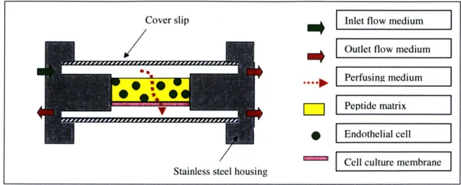
Two types of flow experiments are possible with the bioreactor. Cells can be seeded in 2D, which means the cells are seeded as a monolayer on top of the gel (Figure 2.2), or cells can be seeded in 3D, which means the cells are suspended in the peptide solution and allowed to gel in the device (Figure 2.3).
Cover slip
SmtE
Stainless steel housing
-Inlet flow medium
Outlet flow medium
Perfusing medium
Peptide matrix Endothelial cell
Cell culture membrane
Cover slip Inlet flow medium
Outlet flow medium
Perfusing medium VPeptide matrix
S Edteial cell
ICell culture membrane Stainless steel housing
Figure 2.3. Cross sectional view of 3D experiment in bioreactor
2.3. Flow Properties
Several flow characteristics were considered in the design of angiogenesis xperiments in the macroreactor. First, oxygen transport was analyzed to ensure cells vould have a sufficient oxygen supply during an experiment. Second, a scaling analysis
f the diffusion time scale was computed to determine how long the peptide solution ould take to gel. Finally, in order to quantify the shear stress acting on the endothelial ells in the peptide matrix, a computational fluid dynamics (CFD) was implemented to model the flow properties entering the cell culture region.
2.3.1. Oxygen Transport
Oxygen transport to the cells in the peptide gel was delivered by the top and ottom chambers of the bioreactor, as well as by the perfusing flow through the scaffold. n order to determine if oxygen transport was dominated by diffusion or convection the
ectl number was calculated
Pe = LU (2.1) D e V c b I P
where L is the characteristic diffusion length, U is the average macroscopic velocity, and D is the diffusivity of 02. The diffusion coefficient of oxygen in tissue at 37"C is 2 x 10⁻⁵
cm2 [16]. For the bioreactor, L = 7.5 mm and U = 10 pm/s, and Pe 0 0 (10). For Pe>> 1, it can be assumed that diffusion can be neglected.
The necessary perfusion rate to supply oxygen to the endothelial cells at an oxygen consumption rate,
Q
0, = 13.1 pM/min [58] was calculated using the followingequation:
q = Qo2 (2.2)
C0
where Vce.ls is the volume of endothelial cells seeded in the peptide gel,
Q
0 is the oxygen consumption rate of an endothelial cell, and Co is the oxygen concentration [16]. Based on endothelial cell diameter of 10 pm and a cell seeding density of 5 million cells/mL in the bioreactor,Q
0, = 13.1 uM/min [58], and an oxygen concentration in bulkapproximately equal to the aterial plasma, Co = 0.13mM [59], the necessary perfusion rate, q = 0.0002 pL/s. On comparison with the experimental perfusion rate for U = 10 pim/s, this will be a sufficient oxygen supply for the cells.
2.3.2. Diffusion Analysis
Once the peptide solution and cells are seeded in the bioreactor, peptide gel formation is promoted by the introduction of a saline solution. The rate at which the peptide solution will gel is dependent on the rate at which salt ions diffuse into the peptide sample. A 1% weight peptide solution (10 mg/mL) is 99% water, so the diffusion rate of the NaCl ions can be approximated by the diffusivity of NaCl ions in
water. For a species with diffusivity D, the approximate diffusional length scale, delta is given by
~ 2D (2.3)
where T,,ff is the diffusional time scale. Gelation will be promoted by a saline solution
(IX Phosphate buffered solution) and the diffusivity for a IM salt solution (DNaC = 1.483
x 10-5 cm2/s at NaCl concentration =
0.1M, at 25C) is estimated [60]. The length scale that the NaCl ions must travel, h, will be equal to the height of the washer component that the peptide and cells are placed in. Since the saline solution will be entering from both the top and bottom of the sample, the diffusion length 6 is half the dimension of that region. =- (2.4) 2 Substitution yields Vdiff -6h (2.5) 16D
For a desired peptide gel thickness in the macroreactor of 1.0 mm, the diffusion time of the NaCl ions was estimated to be 10.5 seconds.
2.3.3. Shear Stress
The shear stress across the cell culture region was estimated by analyzing the flow across the surface of the peptide gel. One of the advantages of using the referenced bioreactor, it that a CFD model was previously developed to model the shear stress in the bioreactor for given flow parameters [16]. The CFD model was solved using commercial software, ADINA v7.4 (ADINA R&D Inc., Watertown, MA). The CFD model
implemented a finite element solution of the Navier-Stokes solution in 3D with several assumptions. First, the velocity profile at the inlet of the upper chamber was assumed to be uniform. Second, no-slip boundary conditions were imposed at the outlet and the walls. The Reynolds number was based on the width of the upper chamber and the diameter of the tissue-flow channels and was approximately - 0(1) [16].
The input parameters for these models were selected to match the physiological values cited in previous in vitro studies of endothelial cell behavior. Two experimental models were proposed for flow across the gel: a low shear and a high shear model. The aim of the low shear model (0.3 dynes/cm2) was to apply a negligible shear force on the
surface of the gel or to the endothelial cells seeded in the gel. The aim of the high shear model (10 dynes/cm2) was to apply a shear force on the scale of the shear stress on the
endothelium in vivo. For flow through the gel, the driving pressure was selected to be 10 mmHg, which is the typical pressure dron across a capillary.
The CFD model was run with the desired control and experimental shear stress rates and the desired inlet flow rates were calculated to be 1.5 mL/min and 46.5 mL/min for the control and experimental values of shear stress, respectively [61]. Additionally, plots of the shear distribution across cell culture area were generated for the control and experimental parameters, which demonstrated some non-uniformity of shear on the surface of the peptide gel region [61].
2.4. Biological Materials & Methods
The experimental setup of the bioreactor consisted of both biological and non-biological preparations. The protocol for assembly of the bioreactor was previously
documented, so the protocols developed for the angiogenesis experiments focused on the optimization of peptide and cell culture preparations.
2.4.1. Self- Assembling Peptide Gel
RADA16-II peptide (Synpep Corp., Dublin, CA) was used for the experiments (R
= arginine, A = alanine, D = aspartic acid). The chemical structure of the amino acids, sequence and molecular structure of RADAI 6-II is shown in Figure 1.5. A I% solution (10 mg/mL) of the RADA16-II peptide was prepared in sterile double-distilled water. After mixing, the peptide solution was initially vortexed for 30 seconds at low speed, following by alternating vortexing (Mini Vortex VM-3000, VWR) and sonicating (Aquasonic Model 50HT, VWR) every 5 minutes, for 30 minutes or until the peptide is completely dissolved. The amount of peptide solution to fill the cell seeding area was based on the volume of the washer; with an adjustment for a measured 10% contraction in volume after the solution formed a gel.
2.4.2. Cell Culture
Bovine aortic endothelial cells (BAECs) were isolated from fetal aorta according to published protocol (Williams KS, 1996) and cultured on 1% gelatin (#G-1890, Sigma Aldrich, St. Louis, MO) coated T-75 flasks (29186-105, VWR, West Chester, PA). Cell culture medium was prepared and changed every 2 to 3 days (10% Defined Fetal Bovine Serum (SH30070.03, HyClone, Logan, UT), 1% Penicillin-Streptomycin (15140122, Invitrogen, Carlsbad, CA), I% Endothelial Mitogen (BT-203, Biomedical Technologies, Stoughton, MA), 2% Heparin (H3149-50KU, Sigma Aldrich), 1% L-Glutamine (25030081, Invitrogen), 85% Medium 199 (M7528, Sigma Aldrich)).
Cells were incubated for 5 to 7 days until confluent. After treatment with trypsin (#SH 30042, HyClone), the endothelial cells are centrifuged (1400 rpm @ -4C) for ten minutes. All excess fluid is aspirated and the cell pellet is re-suspended in a small volume low pH medium. The goal of the low pH medium was to prevent the peptide solution from gelling when mixed with the cell pellet. The pH of this medium was optimized based on observed cell viability in various concentrations (A.2.1, Figure A.2.1). For 3D seeding experiments, the final cell seeding density in peptide gel was 5million cells/mL. Cells were counted prior to seeding using a hemacytometer (#1483, Hausser Scientific, Horsham, PA).
2.5. Bioreactor Materials & Methods
The macroreactor assembly protocol was followed and was modified as needed to fit the requirements of the peptide gel experiments.
2.5.1. Peptide Scaffold
First, the structural component for seeding the peptide hydrogel and cells was constructed. The Stycast adhesive curing agent was combined with base at ratio of 5:1 and mixed continuously for 5 minutes. The stainless steel washer was adhered to the cell culture membrane and allowed to set for 24 hours, after which the excess membrane was cut away, and the entire insert was sterilized in 70% ethanol for 30 minutes. All the bioreactor housing, parts, tubing, fluidic fittings, reservoirs, and tools were autoclaved. The bioreactor parts were assembled in the hood and the custom cell culture insert for the peptide gel was secured in the bioreactor.
Once the cells are suspended in the low pH media, the peptide solution was removed from the sonicator, the cells were gently suspended in the peptide solution with a 200pL micropipette, and the mixture was carefully placed on the cell culture membrane in the bioreactor. The bottom chamber of the bioreactor was assembled and infused with medium, and a small volume of media was placed on top of the peptide and cell solution to promote gelation, as well as provide sufficient nutrients to the cells. Finally, the cover slip of the top chamber is placed on top of the sample, sealed with autoclaved vacuum grease, and fastened tightly to prevent leaks.
2.5.2. Flow Delivery
Once the cells were seeded in the peptide matrix, three difference flow patterns were possible: flow across the gel, cross-flow through the gel, and flow across and through the gel. In order to maintain a sufficient supply of oxygen and nutrients to the cells as well as maintain a constant level of pressure across the gel a peristaltic pump was used to control flow across the gel (Peristalic Pump P-3, Pharmacia Fine Chemicals, Piscataway, NJ). In addition to establishing a flow across the gel construct, a slight hydrostatic pressure drop was used to promote the flow of media through the thickness of the gel and through the thin membrane support. A schematic of the flow path diagram for a flow across and flow through experiment is shown below in Figure 2.4.
Penstabc . Punmp
Flow across gel
Rec ivoir
Flow through gel
Lowei Rescrvou
Figure 2.4. Flow diagram for bioreactor experiment
Two reservoirs of medium were needed for maintaining flow through the device: an upper reservoir and a lower reservoir. Pyrex@ graduated media bottles (500 mL) were used as fluid reservoirs (#1395-500, Coming, Corning, NY), and the caps were fitted with female luer connections for tubing and sealed with silicone glue (Cole Parmer). The upper reservoir serves as the inlet for all flow into the bioreactor. The lower reservoir collects flow through the gel and is placed at a height such that a pressure difference is maintained between the upper and lower reservoir. A second pump (not shown) was used to re-circulate the media flow through the gel to back to the upper reservoir (Pump P-1, Pharmacia Biotech, Uppsala, Sweden). Silastic® silicone tubing (1/8" ID x 1/4" OD) was used for all fluids connections (#515-012, Dow Coming, Midland, MI).
2.6. Device Validation
After the bioreactor device was assembled with the peptide gel, a number of studies were performed to validate the performance of the macroreactor. In particular, the hardware and fluidic fittings were assessed for leaks and the connectors for the reservoirs and pumps were fitted to go inside the incubators. Experiments were performed to measure the flow through the peptide gel in the bioreactor at 37'C once the system and hydrostatic reservoirs were setup in the incubator. This data was used to calibrate to pump flow rates to achieve the inlet flow rates of the CFD model.
2.7. Summary
In summary, an in vitro model for culturing hepatocytes was modified for 3D studies of endothelial cell behavior in a self-assembling peptide matrix under two levels of shear stress: 0.3 dynes/cm2 and 10 dynes/cm2. Experiments were conducted to study
angiogenesis in this device using hydrostatic pressure and a peristaltic pump to control flow. Results to characterize angiogenic activity due to flow were assessed using fluorescent and confocal microscopy.
![Figure 1.4. Mechanisms of angiogenesis [9]](https://thumb-eu.123doks.com/thumbv2/123doknet/14685032.560019/21.918.175.727.140.521/figure-mechanisms-angiogenesis.webp)