3rd International Conference on Bio-Based Building Materials
June 26th - 28th 2019
Belfast, UK ID_ PP176
LATERAL LOAD CARRYING CAPACITY OF TIMBER WALLS FILLED HEMP
CONCRETE: EXPERIMENTAL AND NUMERICAL INVESTIGATION
H. Wadi1,*, S. Amziane1, E. Toussaint1, M. Taazount11 Université Clermont Auvergne, Institut Pascal UMR 6602 CNRS, 63178 Aubière, France.
*Corresponding author; e-mail: husam.wadi@etu.uca.fr
Abstract
The use of bio-based materials in structures improve the insolation level and sound absorption. In response to this need, the use of bio-aggregate such as hemp shives is increasing in Europe and especially in France. Hemp concrete is now used in construction as a sustainable and carbon neutral infill wall material around timber-framed construction. This study concerns on the effect of wall dimensions on the in-plane racking strength of timber frame walls filled with hemp concrete. Two wooden geometrical configurations were used, the first was diagonal bracing walls , and the second was vertical stud walls. These two types of timber walls are most widely used in construction subjected to lateral loads. In this study, a numerical and an experimental investigation of large-scale timber walls both with and without hemp concrete were carried out to investigate the contribution of this filling material against the lateral loads. Digital Image Correlation (DIC) technique was used in order to track local displacements and shear strains fields of hemp concrete in the wall. The hemp walls then compared to empty frames.
This study focuses also on the numerical investigation of the lateral-load carrying capacity of hemp concrete as infill material in timber frame walls, investigating and highlighting the parameter that significantly affect the lateral resistance of hemp walls. For this purpose, the vertical studs timber frame walls with dimensions (2.5m height and 1.2m length) were used as the bench mark to validate the previous experimental work. Also a numerical study of three timber walls filled with hemp concrete has been studied to verify the effect of wall length of the lateral load carrying capacity of hemp concrete. Three vertical stud timber walls with a standard height 2.5m and different lengths (1.2 m, 1.6 m and 2.4 m) were investigated using Abaqus software. Based on the numerical and experimental tests, this study confirms, firstly, that hemp concrete has a small participation against lateral loads with wall dimensions 2.5 m height and 1.2 length. In fact it cannot be generalized that hemp concrete has always a significant strength in timber wall. The filling material could not work mechanically against lateral load without a complete form of compression diagonal zone which make the material loaded under shear forces. This zone is related to the dimensions of the wall and is present when the ratio between the height and the length of the wall (L/h) ≥1. Within this limit, the material mechanically works, otherwise, the results are totally different.
Keywords:
Hemp concrete, Timber frame walls, Lateral load carrying capacity of hemp material, Digital Image correlation.
1 INTRODUCTION
Construction and public projects nowadays are facing a significant challenges of reducing energy consumption due to the large amount of using daily services such as heating, electricity and hot water in the residential and commercial buildings especially in Europe. For this purpose, many buildings regulations try to use now bio-base materials with a high quality of physical properties in construction sectors. The use of low carbon material in structures will firstly, improve the insolation level and sound absorption and secondly, will decrease the weight of building because this natural material considered as a lightweight aggregate. In response to this need, the use of bio-aggregate such as hemp, flax and sunflower is increasing in Europe and especially in
France [1]. Wood is one of the most widely used building materials in many countries in the world, because it has a good physical properties and environmentally friendly [2]. Timber walls are frequently used as a structural system in the buildings designed to withstand lateral loads and transfer these forces to the foundations with ductile behaviour [3]. Timber shear wall consists of timber frame and sheathing board, connected by fasteners. The sheathing board may be made of a variety of materials, such as Oriented Strand Board [4- 7]. Hemp particles are a natural low carbon material used to reduce energy consumption in buildings [5]. Nowadays this natural material is used in construction as infill wall material within timber framed construction in Europe and especially in France [5].
2 THEORETICAL APPROCH
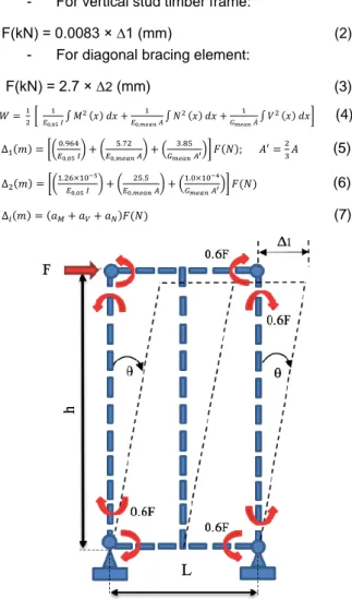
Two different shapes of timber walls were considered in this study, vertical stud and diagonal bracing walls (see Fig. 1 & 2). A linear elastic behaviour of the wall-unit were assumed in this approach, also the deformations are caused by only external force. By applying the virtual work transformation by unit-load theorem (F), the total top displacement of the wall unit (∆) can by calculated as:
∆ = 𝜕𝑊
𝜕𝐹 (1)
Where (w) is the elastic strain energy stored in the wall and provided by an external horizontal load (F) applied on the top of the wall unit. In the present case, the total strain energy consists of three internal forces: anormal force (N), shear force (V) and an internal moment (M) as illustrated in equation (7). By taking the material characteristics into account, then the total horizontal displacement (∆1) in vertical stud wall can be calculated
as a function of the internal forces by equation (5), also the total horizontal displacement (∆2) in the diagonal
bracing wall can be calculated by equation (6) using the same principle.
- For vertical stud timber frame:
F(kN) = 0.0083 × ∆1 (mm) (2) - For diagonal bracing element:
F(kN) = 2.7 × ∆2 (mm) (3) 𝑊 = 12 [ 𝐸1 0,05 𝐼∫ 𝑀 2(𝑥) 𝑑𝑥 + 1 𝐸0,𝑚𝑒𝑎𝑛 𝐴∫ 𝑁 2(𝑥) 𝑑𝑥 + 1 𝐺𝑚𝑒𝑎𝑛 𝐴́∫ 𝑉 2(𝑥) 𝑑𝑥] (4) ∆1(𝑚) = [(𝐸0.964 0,05 𝐼 ) + ( 5.72 𝐸0,𝑚𝑒𝑎𝑛 𝐴 ) + ( 3.85 𝐺𝑚𝑒𝑎𝑛 𝐴′ )] 𝐹(𝑁); 𝐴′=2 3𝐴 (5) ∆2(𝑚) = [(1.26×10 −5 𝐸0,05 𝐼 ) + ( 25.5 𝐸0,𝑚𝑒𝑎𝑛 𝐴) + ( 1.0×10⁻⁴ 𝐺𝑚𝑒𝑎𝑛 𝐴′)] 𝐹(𝑁) (6) ∆𝑖(𝑚) = (𝑎𝑀+ 𝑎𝑉+ 𝑎𝑁)𝐹(𝑁) (7)
Fig. 1: Loaded and unloaded state of vertical stud wall unit.
It was obvious that on the first hand, normal and shear forces in the vertical stud walls are negligible compared to the value of internal moments (1.2 ×10⁻4). On the second hand, shear forces and internal moments are negligible in the diagonal bracing case compared to the value of normal forces (3.5×10⁻7) as presented in previous Figures (1 & 2).
Fig. 2: Loaded and unloaded state of diagonal bracing wall unit.
3 EXPERIMENTAL RESULTS
3.1 Vertical stud walls
The empty vertical stud wall was considered as a control frame for comparing with hemp walls. The maximum load bearing capacity of the empty frame was around 0.18 kN as illustrated in Fig. 3. It was obvious that the theoretical approach describe the elastic behavior of the wall and matches the initial experimental behavior results (Fig 3). Vertical stud hemp walls (V-H) were tested with the same set up and method as illustrated in Fig. 4. The average load bearing capacity of the vertical stud hemp wall was around 2 kN.
Fig. 3: Force-Displacement behavior for frame only.
3.2 Diagonal bracing walls
The load bearing capacity of empty diagonal bracing walls was presented below in Figure 5 by force-displacement plots. The average maximum load bearing capacity of diagonalbracing wall was 10.78 kN. The theoretical behaviour of diagonal bracing wall did not show the same behaviour of the experimental results (Fig. 5) this difference is related to the joint consideration. It is clear from the results that the experimental behavior of the wall is less rigidity than the mathematical approach. Figure 6 presents the lateral strength of diagonal bracing walls filled with hemp concrete (D-H) and obviously, the hemp concrete did not contribute in the lateral strength with the diagonal bracing wall and no clear contribution of the hemp concrete in both cases in the lateral resistance as infill material in the diagonal configuration.
Fig. 5: Force-Displacement behavior for diagonal bracing walls.
Fig. 6: Force-Displacement behavior for diagonal bracing walls filled with hemp concrete.
3.3 DIC analysis
The results of shear-strain fields obtained with DIC for both vertical stud and diagonal bracing walls are presented in Figures 7 and 8. The horizontal displacement of the wall is around zero at the bottom of the wall and gradually increases as we move towards the top. However, the vertical displacement near the external stud is very small and increases nearer to the middle stud. Figure 7 shows the shear-strain field of the wall and it is obvious that the higher values of shear strain are focused on the corner with average value of 0.0042 which indicates that the hemp particles are deformed according to the external force applied on the top of the wall. Figure 8 presents shear strain fields of the diagonal bracing timber wall. The value of horizontal displacement increases from the bottom to the top of the
wall, and also the value of vertical displacement increases from the external stud to the middle area of the wall. The shear strain of hemp particles has an average value of 0.0021.These results obtained using DIC show that the average shear strain value in the bottom left corner of the vertical stud wall is higher compared to average shear strain value of the bottom left corner of the diagonal bracing wall. This clearly proves that the vertical stud geometry has less rigidity than the diagonal bracing. The high rigidity of the diagonal system prevents the infill material contributing to the horizontal resistance of the wall, which explains why the hemp concrete provides no increase in the strength in the diagonal bracing walls.
Fig. 7: Shear strain of hemp concrete in vertical stud wall (V-H-2) at total horizontal displacement of 50mm.
Fig. 8: Shear strain of hemp concrete in diagonal wall (D-H-2) at total horizontal displacement of 50mm.
3.4 Analysis of the experimental tests
The experimental results show the advantages of hemp concrete in vertical stud wall against the applied lateral loads. Obviously, hemp concrete makes a lesser contribution to the lateral load-carrying capacity in the vertical stud wall. The racking strength of the empty frame is around 0.18kN. In contrast, the average racking strength of vertical stud hemp walls is around 2kN, which indicates that hemp concrete increases the horizontal capacity nearly tenfold as compared with the empty frame and provides more rigidity. As shown in the
representative curve of vertical stud hemp wall in Figure 9, the initial strength appears at the beginning of the curvature of the walls (Zone ) due to the existence of a rotated steel angle at the top of the wall to prevent separation of the vertical stud from the top rail. In Zone , the strength of curves becomes constant with a continuous increase of displacement due to the gap between the hemp material and vertical timber studs. In Zone , the strength increases with more rigidity compared to the first zone; this strength is due to the direct contact between the vertical studs and hemp concrete. In the diagonal bracing walls, it is clear that the diagonal element alone increases the total rigidity of the wall. This high rigidity prevents the hemp concrete from contributing to improving the results when measured against lateral loads. The average displacement of a diagonally braced wall in linear behavior in the experimental test is around Exp =
20mm. However, the theoretical average displacement is around Theo = 4mm. The system coefficient can be
calculated as: (Theo /Exp) 100% = 20%. The theoretical model can describe only 20% of the actual experimental behaviour of the diagonal timber walls. This comparison confirms that the diagonal bracing wall is complicated and its experimental behaviour shows it is not suitable for use with filling material. Obviously, the two designs of timber walls behave differently with the same filling material. On one hand, the participation of hemp concrete provides more than ten times the strength in a vertical stud wall, compared to the empty frame. On the other hand, the contribution of hemp concrete is practically non-existent in the diagonally braced wall. Simply put, the forces did not transmit to the filling material in the diagonally braced wall due to the high rigidity of the whole system. However, in the case of vertical stud walls, which have less rigidity, the forces easily transmit to the filling material, and it has great impact on the lateral strength performance. The results obtained from the camera analysis also confirm this explanation, with the value of the shear strain in the vertical stud hemp wall being doubled, compared to the diagonal bracing. Despite the contribution of hemp concrete with vertical stud walls, this contribution is still insufficient. In fact, the dimensions of the timber wall (L/h) play the main role in making the filling material effective when loaded under shear forces.
Fig. 9: Representative curve for the lateral load resistance of vertical stud hemp wall.
4 NUMERICAL ANALYSIS OF TIMBER WALL
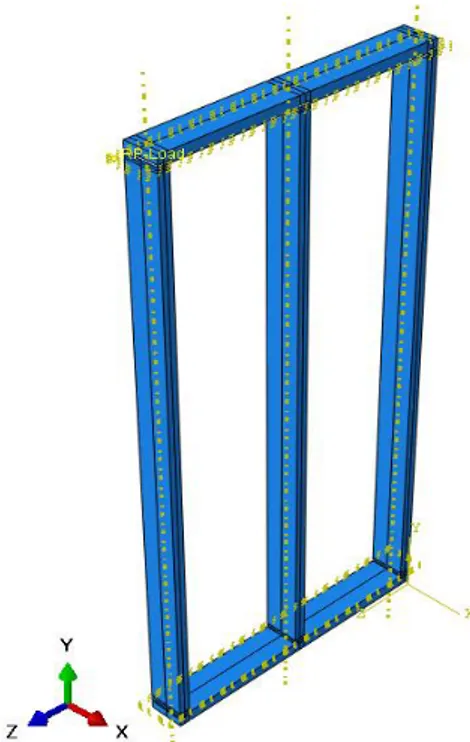
A vertical stud timber frame wall with a real scale was considered in this study in order to validate the experimental study of empty and filled timber walls. The frame was considered of three vertical stud studs with two rails. The total dimension of the timber wall was
2.5m height and 1.25 m length as illustrated in the Figure 4.1 below. The cross sectional area of the studs and rails were 45 mm by 145 mm. The material properties of elastic behaviour of wood were defined by the Young’s modulus of 11000 MPa and Poisson’s ratio 0.2 with Isotropic assumption. Also the nails parameters were defined an represented in this model with isotropic behaviour as the following, Nail diameter was 2.8 mm, head diameter was 6.5 mm, nail length was 90 mm, characteristic withdrawal parameter (fax,k) was 17.49N/mm2, characteristic yield moment (My,k) was
3235 N.mm and characteristic tensile capacity (ftens,k) was 4.19 KN. The hinges in each connection timber to timber were considered as non-linear behaviour with the possibility of rotation. The properties of hinges were assigned according to the shear and the rotational stiffness respectively. The hemp concrete material also defined with a value of 37 MPa of modulus of elasticity and 0.1 Poisson’s ratio. Linear and non-linear analysis were used in order to define the capacity of timber frame wall.
Fig. 10: Model geometry of the vertical stud timber wall.
4.1 Contact interaction
General contact interaction in Abaqus can define contact between many or all regions of the model with a single interaction. In this simulation, the column was assumed as master surface and the beam as slave surface in each timber to timber joint with a degree of smoothing for master surface of 0.2. The discretization method considered in this analysis was Surface to surface. The normal behaviour of contact properties for timber to timber was defied as hard contact. The tangential behaviour was defined by the value of friction coefficient 0.8. In case of nail-timber contact interaction, the nail surface was considered as the master surface and the timber part was consider as the slave surface with a degree of smoothing for master surface of 0.2. also the discretization method considered in this analysis was Surface to surface standard. The normal behaviour of contact properties for nail to timber was defied as hard contact and the tangential behaviour was defined by the value of friction coefficient 0.5.
The joint for the empty timber frame wall was simulated as the real case at the laboratory tests. Each joint between column and beam was consists of three ring nails with full rounded head as illustrated in Figure 11 below. The contact surface between the rounded surface of timber in each hole and the rounded surface of fastener was simulated as a general standard contact considering the fastener as the master surface and the wooden part as the slave one.
Fig. 11: Simulated timber joint with represented nails.
Fig. 12: Mesh of Finite Element Model for timber frame wall.
4.2 Numerical results validation
After checking the complete numerical model for the empty timber frame wall, a comparison with experimental tests on full scale wall results was developed. Figure 13 below illustrates that the lateral load carrying capacity of timber frame wall was predicted by the complete numerical model and compared with load vs displacement curve. The results show a considerably good coincidence between the proposed numerical model and experimental results. According to the comparison below it is obvious that the preliminary stage of strength of the experimental result was slightly less than the numerical model result at a displacement of 45 mm in the elastic zone of the wall. This difference is due to the transport of the timber frame at the laboratory which decrease the rigidity of the joint especially that the frame is empty which made the joint more affected with the movement. Two top steel beams were fixed on both side of the timber wall at the laboratory before starting the test. The main objective of using these two beams was to keep the tested wall in-plane and present it from moving out of in-plane. These two beams were fixed with the set up and space of 2 cm were kept between the wall and the beam. During test, the wall touched the steel beam from one side which created a slight friction between the top wooden rail and the steel beam. This friction added a small strength to the results and explain the difference between the experimental and the numerical results at the zone beyond 45 mm of global displacement.
Fig. 13: Comparison between the experimental and the numerical results of empty timber wall.
In Figure 14 a comparison between the numerical and experimental results was plotted below. The experimental results were consist of three zones the first one was related to the steel angle fixed on the timber joint, second was related to the gap between the hemp material and the timber stud and the third was the real contribution of the hemp concrete. For this reason, the numerical curve was shifted to the right in order to compare the elastic linear behaviour between two cases. This space was around 27 mm. Considering the first wall (V-H-1) as a bench march for the comparison, the elastic behaviour of the numerical model was matching the behaviour of wall at the laboratory, however the plastic region was little far beyond 50 mm of the global lateral displacement. The reason behind the difference between the proposed model and the experimental tests is simple, the gap between the hemp material and the timber stud was playing a main role of decreasing the total lateral load carrying capacity of the wall during the experimental tests. In contrast, this gap in the proposed model was not exist and the two materials (timber and hemp) was assumed to behave as one piece. This assumption was considered in the proposed model on the first hand, to simplify the analysis and on the other hand, studying the contact between two materials in large scale is a complicated analysis.
Fig. 14: Comparison between the experimental and the numerical results of timber wall filled with hemp.
4.3 Numerical analysis from different lengths of timber walls filled with hemp concrete
A numerical study has been investigated for the same geometry of the timber frame wall with different lengths to investigate the effect of the wall length on the lateral load-carrying capacity of hemp concrete. For this purpose, two different lengths of timber frame wall ( 1.8 m and 2.4 m) were considered in this study as the length of 1.2 was investigated in the previous section. The first wall geometry was consisting of three panels with height
2.5 m and length 1.8 m (length of each panel equal to 60 cm). The second wall geometry was consisting of four panels with height 2.5 m and length 2.4 m. The height of all walls was constant as the wall length is the parameter that included in this study.
Numerical analysis was carried out for timber frame wall of three panels with height 2.5 m and length 1.8. The same conditions as previous model were considered in order to determine the lateral load carrying capacity of the hemp concrete subjected to lateral loads and also study the effect of wall length on the horizontal strength of the wall. Figure 15 below illustrates the force-displacement curve of three panels filled with hemp concrete. The results below shows that the total lateral strength of hemp concrete in elastic zone has been improved from 2.3 kN to 6.2 kN due to the increase of the wall length from 1.2 m to 1.8 m respectively.
Fig. 15: Lateral strength of hemp wall three panels with length 1.8 m.
Timber frame wall of four panels filled with hemp concrete (length 2.4 m) was analysed with the same method as the previous walls. Figure 4.16 below presents the lateral behaviour of hemp concrete as infill material in timber frame with four panels. The results below show that increasing the length of the wall to 2.4 m significantly improved the rigidity and the lateral load carrying capacity of hemp concrete as infill material. The lateral strength of the hemp wall was around 8.1 KN in the elastic zone of the global performance of the wall.
Fig. 16: Lateral strength of hemp wall four panels with length 2.4 m.
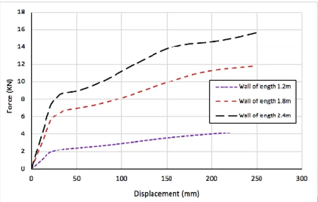
The numerical results show the contribution of hemp concrete in vertical stud timber wall subjected to lateral loads as shown in figure 17 below. Obviously, hemp concrete participates as infill material to the lateral load carrying capacity of vertical stud wall. The in-plane strength of vertical stud hemp wall consists of two panels is around 2.1-kN in elastic zone. As shown in the comparison between results for different wall lengths, the lateral strength of hemp concrete improves with increasing the wall length (see Fig. 17). The total horizontal resistance (elastic zone) of wall length 1.2 m,
1.8 m and 2.4 m about 2.1 kN, 6.2 kN and 9 kN respectively. On the first hand, the contribution of hemp concrete provides more than three times the strength in wall of three panels, compared to the two panels wall. On the other hand, the participation of hemp concrete in lateral strength in four panels is not as much as the improvement in the three panels wall. The results obtained from Abaqus software confirm that increasing the wall length will increase the ability of transmitting the forces to the filling material. Figure 17 below presents the effect of the number of panels on the lateral strength of the timber wall filled with hemp concrete in the elastic zone. In fact, the length of the timber wall significantly enhance the hemp concrete participation as infill material and also play a main role in transmitting the hemp concrete from insufficient zone (two panels) to an effective material when subjected to lateral loads.
Fig. 17: Comparison between numerical results with different wall lengths of hemp concrete.
5 CONCLUSION
In this paper, an experimental and numerical studies of racking performance of hemp concrete with two different designs of timber walls (vertical stud and diagonal bracing) were conducted. The hemp filling material increased the lateral resistance of vertical stud timber frame tenfold and the racking stiffness was improved. However, this filling material does not contribute to lateral strength in wall with diagonal bracing. Based on the results of this study, it is impossible to draw a generalised conclusion that hemp concrete always makes a significant contribution to strength in timber walls. The filling material could not work mechanically against lateral loads without complete compression in the diagonal zone, which subjects the material to shear forces. This zone is related to the dimensions of the wall and is present when L/h ≥ 1, approximately. Within this limit, the material makes an appreciable mechanical contribution. Beyond this limit, the results are totally different. Also, the overall rigidity of the timber wall affects the contribution of hemp concrete against lateral loads. This study confirms that the contribution of hemp concrete in the lateral strength of the timber wall depends significantly on the length of the wall, since the height is fixed. Also installing hemp concrete in a very highly rigid system will prevent transmission of forces to the filling materials and thus decreases its improvement of lateral resistance measurements: the more rigid the wall is, the less resistant the hemp is.
6 REFERENCES
[1] S. Amziane, L Arnaud, editors. Bio-aggregate-based building materials: applications to hemp concretes. London, Holboken: ISTE Ltd., 2013. [2] M. Premrov, M. Kuhta. Influence of fasteners
disposition on behavior of timber-framed walls with single fibre-plaster sheathing boards. Construction
and Building Materials 23(2009) 2688-2693.
[3] Wei Y. Loo, Pierre Quenneville, Nawawi Chouw. A numerical study of the seismic behavior of timber shear walls with slips-friction connectors.
Engineering Structures 34 (2012) 233-243.
[4] Johan Vessby, Erik Serrano, Anders Olsson. Coupled and uncoupled nonlinear elastic finite element models for monotonically loaded sheathing-to-framing joints in timber based shear walls. Engineering Structures. 32 (2010) 3433-3442.
[5] C. Gross, P. Walker, Racking performance of timber studwork and hemp-lime walling.
Construction and building Materials.66 (2014)
429-435.
[6] Bevan R, Woolley T, Pritchett I, Carpenter R, Walker P, Duckett M. Hemp lime construction: a guide to building with hemp lime composites. IHS BRE Press;2008.
[7] H. Wadi, S. Amziane, “Mechanical behaviour of unclassified timber walls against horizontal forces” national conference, Nantes, France.
[8] Christopher G, Pete W. Racking performance of timber studwork and hemp-lime walling. Constr Build Mater 2014; 66: 429–435
[9] S. Hans, F. Sallet, L. Goudet, Mechanical behaviour of wooden framework buildings with sprayed hemp concrete. ICBBM international conference, June 2017.