Publisher’s version / Version de l'éditeur:
Vous avez des questions? Nous pouvons vous aider. Pour communiquer directement avec un auteur, consultez la première page de la revue dans laquelle son article a été publié afin de trouver ses coordonnées. Si vous n’arrivez pas à les repérer, communiquez avec nous à [email protected].
Questions? Contact the NRC Publications Archive team at
[email protected]. If you wish to email the authors directly, please see the first page of the publication for their contact information.
https://publications-cnrc.canada.ca/fra/droits
L’accès à ce site Web et l’utilisation de son contenu sont assujettis aux conditions présentées dans le site
LISEZ CES CONDITIONS ATTENTIVEMENT AVANT D’UTILISER CE SITE WEB.
Internal Report (National Research Council of Canada. Division of Building Research), 1961-01-01
READ THESE TERMS AND CONDITIONS CAREFULLY BEFORE USING THIS WEBSITE. https://nrc-publications.canada.ca/eng/copyright
NRC Publications Archive Record / Notice des Archives des publications du CNRC :
https://nrc-publications.canada.ca/eng/view/object/?id=b642a343-ded4-497e-be58-ecc82f6f2214 https://publications-cnrc.canada.ca/fra/voir/objet/?id=b642a343-ded4-497e-be58-ecc82f6f2214
Archives des publications du CNRC
For the publisher’s version, please access the DOI link below./ Pour consulter la version de l’éditeur, utilisez le lien DOI ci-dessous.
https://doi.org/10.4224/20358941
Access and use of this website and the material on it are subject to the Terms and Conditions set forth at Determination of outside surface temperature of a chimney with an analogue computer
NATIONAL RESEARCH COUNCIL CANADA
DIVISION OF BUILDING RESEARCH
DETERMINATION OF OUTSIDE SURFACE TEMPERATURE OF A CHIMNEY WITH AN ANALOGUE COMPUTER
by
G. T. Tamura and G. P. Mitalas
t\セLj t'\L'{ ZE0
Internal Report No. 238
of the
Division of Building Research
OTTAWA
This report represents a further small advance in knowledge of the temperature and heat flow characteristics
of masonry chimneys. It deals with the influence of cycling
furnace operation on the chimney surface temperature which
is of concern primarily from a safety point of view. This
study represents a further use also of the analogue computer which is often of great assistance in the solution of heat flow problems arising in buildings.
The authors are research officers with the Building
Services Section of the Division. The first author is
responsible for the work being carried out on the thermal and safety aspects of chimneys; the second author is engaged in studies of heat transfer through various bUilding elements and of bUilding heat losses and gains using analogue and
computer techniques.
ottawa
DETERMINATION OF OUTSIDE SURFACE rrEIVLPERATURE OF A CHIMNEY WITH AN ANAI,OGUE COMPUTER
by
G. T. Tamura and G. P. Mitalas
To provide for the safe discharge of flue gas, a chimney must have sufficient thermal resistance to prevent
overheating of the surrounding construction. The resistance
of the walls of a chimney to heat flow should be such that the outside surface temperature does not exceed a safe value. Therefore to evaluate the fire safety of a chimney, informa-tion on its outside surface temperature at anticipated
operating conditions is required.
Information on outside surface temperatures of residential masonry chiw1eys was obtained in fire hazard
tests conducted in the DBR chimney laboratory
(1).
Thesechimneys were fired at steady inlet temperatures based on the maximum flue gas temperature at the outlet of the various heating appliances.
Over most 'of the range of flue gas input tempera-tures used in the tests, the outside surface temperatempera-tures of the chimneys were in excess of values normally considered
maximum for combustible materials. Since these chimneys
appear to provide safe conditions in the field, it is
necessary to look critically at both the generally accepted safe temperature limits for combustibles and the test
conditions. This report deals with one aspect of the latter,
the assumption of a constant flue gas input temperature to steady state.
Under normal operations the flue gas temperature outlet from the heating appliance is seldom at a steady level. With a hand-fired solid fuel unit, the temperature of the
flue gas depends on the rate of firing by the operator to
meet the house heating requirement. In gas and oil-fired
units controlled by a room thermostat, there is an on-off firing cycle with the flue gas temperature at maximum value
during the on cycle. Only in extrremeLy cold weather or with
an under-size unit is firing likely to be steady at the
maximum flue gas temperature. The effect of a variable flue
gas input temperature on the outside surface temperature of masonry chimneys was studied with an analogue computer; the results are given in this report.
Analytical determination of the outside surface temperature is complicated by the fact thatihe inside and
outside film conductances, 。」」ッqセエゥョァ for both convection
and radiation, are in part dependent on the surface tempera-tures which are not Imown; a tedious iterative calculation
is required. This is further complicated by the shape of a chimney and the variable nature of the flue gas temperature. With an analogue computer the heat transfer mechanism in a
chi@ley is represented by an electrical circuit; the thermal characteristics of a chimney may now be obtained readily.
Heat transfer in a square masonry chimney was
represented by a two-dimensional analogue network. Because
of its symmetry it was necessary to simulate only a 1/8
section of the chimney with the analogue network. The inlet
flue gas temperature was represented by a periodic voltage input to the network supplied by a relay amplifier circuit. This simulation of the heat transfer problem with an analogue
computer (Race) provided means of dealing with the physical system directly, and means of rapidly investigating the effect of parameters.
Surface temperature readings obtained from the analogue computer with steady voltage input were compared with those obtained during chimney tests conducted in the
laboratory. This comparison gave means of evaluating the
basis for determining the film resistance. DESCRIPrION OF ANALOGUE NETWORK
Consider Fourier's equation for two-dimensional heat flow (1) where 9 = temperature, of 0(
=
thermal diffusivity, ft2/hr t=
time, hr.From equation (1), temperature relationship of the lumped
system may be obtained. Consider Taylor's series expansion:
1'''(
x0 ) (x - x0 )2 f(x)=
f(x o) + f' (xo) (x-x o) +2!
+ + fn-l (x o) (x - xo)n-l (n - I)! (2)...
where - 3 -let f(x)=
G f(x )=
G 0 0 セg f(x)=
G_ 1 f' (xo) _ 0 -1-d-X
c3
2G f(x)+l=
G+1 f" (x ) _- S""""20 0d
xThen, considering temperature in the x
d
2G + 0セ
d
G d2G G+1=
Go + セ セ x + 0d
Xa7
Add (3) and (4), direction, G_ 1 + G+1 - 2Go=
(.A x)2similarly in the y direction,
G_ 2 + G+2 - 2Go
sUbstituting equations (5) and (6) in (1),
d
Go =0«9_1 + 9+1- 29 9_2 + 9 -290) 0 + +2d
t (Ll x)2 (,6 y)2 if .6 x = boy = L thend
90 0( (9_ 1 + 91 + 9_2
+"9+2 - 49 )J
t =12
0.
(8)The analogue circuit for equation
(8)
is shovm in Fig.1.
Temperatures are represented by voltages and the integrator (dc amplifier with a feedback capacitance) sums the quantities
on the right hand side of equation (8) and then integrates.
A sign inversion occurs across the dc amplifier. Temperature
coefficients are represented by the potentiometers that carry
out multiplication by a constant. Initial condition of
temperature or voltage is placed on the integrator. The
analogue representation of the outside film heat transfer is obtained by considering the heat flow equation at the surface.
h (9 - 9 ) o s a = tK (9) where 9 a = 9 s = 9 i = h o
=
air temperature, ofoutside surface temperature, of
temperature of a point inside the surface
adjacent to 9 s ' of
outside heat transfer coefficient,
(Btu) / (hr ft2 of).
The outside film heat transfer coefficient h depends on heat
transfer by convection and radiation. 0
=
(9 - 9
a) 0.25
5
-hr = 0.171 xc..(g - g J{Hセ
-
Hセj
(11) s a h o = hc + hr wheret.
= emissivity of the outside surfacehc
=
convection coefficient, (Btu)/(hr ft 2 OF)hr
=
radiation coefficient, . (Btu)/(hr ft 2 OF)If outside air temperature is assumed constant, the outside heat transfer coefficient varies in an approximate linear relationship with the surface temperature in the
operating temperature range of a chimney (Fig. 2).
i.e.,
= A Q.
s + B
(12)
The values of Q and Q. were plotted in Fig. 3 and
s 1
approximated their relationship by a straight line equation:
=
The analogue representation is shown in Fig. 4. To determine the inside film coefficient, heat transfer due to forced convection was considered and gas radiation neglected.
Film heat transfer due to forced convection is
= 0.023 (Re)0.8 (p )0.4
where
D = equivalent inside diameter, ft
He = Reynolds number
Pr = Prandtl number
hi = inside film heat transfer coefficient,
(Btu)/(hr ft 2 OF).
Knowing the temperature a nd quantity of flow of the flue gas and the inside dioension of the passage, the inside heat transfer coefficient may be approximated as a linear
function of the gas temperature (Fig.
5).
=
EQ + Fg
Then obtaining an equation for heat transfer at the inside surface h. (Q - Q .) 1 g S = K - (Q. - Q ) L 1 S
(14)
L (EQ + F) (g - Q ) = Q. QIe
g g S 1 s with G = E!!
K and H = F LK then (GQg + H) (Qg - Qs) = Q. Q (15) 1 sAnalogue representation of equation (15) is shown in Fig. 6. The periodic flue gas temperature or voltage input is obtained with a relay amplifier circuit using an integrator
and two potentiometers to control the on and off time. The
magnitude of the input voltage is controlled by a potentiometer. The voltage or temperature readings in any part of the circuit may be read on a digital voltmeter or plotted on a graph with
the xy plotter. For parameter investigation the potentiometers
in the circuit are adjusted to the required values. The entire
P"
7
-The analoGue cireuit was assembled on a patchboard and the potentiometers were set to represent a sinele-course
clay-brick masonry chimney with a clay liner. Thermal
performance of this type of chimney at steady inlet flue gas temperature was obtained in the DBR chimney laboratory. The following conditions were selected for the analogue simulation:
Dimensions:
inside 7 by 7 in.
outside QVセ by 16i in.
Properties: K
=
0.60 (Btu)/(hr ft OF)P
=
112 Ib/ft3 Cp=
0.20 (Btu)/(lb OF)0(
= 0.0268 ft2/hr Computer:time scaling
=
(1 sec computer time = 1 hr actualtime)
magnitude scaling
=
1 volt=
lOoPSimulating outside air temperature of 70°F and flue gas temperatures of 400, 600 and 800°F and 100 cfm flue gas flow, time temperature curves of the outside surface tempera-tures were obtained for both steady and periodic flue gas temperature input.
COMPUTER RESULTS
With steady flue gas temperatures of 400, 600 and 800°F, maximum inside and outside surface temperatures at steady state were compared. with those obtained during chimney
tests in the laboratory. Surface temperatures obtained with
the computer were much lower (Fig.8). This was thought to
be due partly to the low' inside film heat transfer coefficient arrived at by using the forced convection heat transfer equation
(13). This inside heat transfer coefficient was adjusted by
increasing the values on the potentiometers II and G of Fig. 6 until the computer inside surface temperature equalled the
chimney test inside surface temperature. It was found that
with the computer increased and equalled that of the chimney test outside surface temperature.
Inside film heat transfer coefficients were re-calculated from readings of the potentiometers adjusted to give surface temperatures identical with those obtained
experimentally. These values are compared with the heat
transfer coefficient obtained from equation (13).
hi
Flue Gas Temp, of Calculated Computer
Btu/hr ft
2
of Btu/hr ft2
of400 / 1.43 5.05
600 1.52 5.21
800 1.61 5.53
With surface temperatures adjusted to test temperatures, inside film coefficients determined by the computer are much
higher than the calculated values. As only forced convection
was considered in calculating the inside film coefficient, the radiation heat transfer coefficient was calculated.
To determine the gas radiation due to carbon dioxide and water vapour content in the flue gas, the flue gas was analyzed for volumetric composition and the dew point tempera-ture measured to obtain the emissivity and absorptivity values.
Volumetric content of carbon dioxide was Rセ per cent and the
dew point temperature was 64°F corresponding to 0.025 and
.0201 atmosphere partial pressures respectively. Then the
gas radiation equation (2) for gray wall surroundings was applied. .9-
- C1+l)
(E G T 4 4 (16) A- () --r
G -o(GITl) hi = A.1.tg £1 = emissivity of a wall9
-Stefan - Boltzmann constant emissivity of a gas
absorptivity of a gas for radiation from a wall
hi
Radiation Radiation + Convection
Flue Gas Temp, of
Btu/hr f't
2
of Btu/hr ft 2 of400 0.198 1.628
600 0.312 1.832
800 0.645 2.255
The calculated values of the inside film coefficient are still substantially lower than the values obtained with
the computer. It is thought that since the hot flue gas is
f'lowing vertically upwards, the equation for determining the f'ilm coef'f'icient must account for the effect of natural
convection.
With the inside and outside surface temperature adjusted to test temperatures, the effects of a periodic flue gas input on the outside surface temperature were recorded on
the xy plotter. The results for flue gas temperature of 600°F
during on-time and 10°F during off-time are shown in Fig. 9. With equal on- and off'-time and a square wave input, the time temperature curve of the outside surface is of a triangular
wave form. As the period is decreased the amplitude is
decreased until at 10 minutes on- and 10 minutes off-time, the surface temperature curve is similar to the curve obtained
with the stead.y input, but lower in magnitude. During actual
burner operation due to the heat capacity of the appliance, maximum and minimum values of flue gas temperature are not attained instantaneously at burner start-up and shut-down
as assumed. The time temperature curve for a typical
operation of an oil bU1TIer of 10 minutes on 5 minutes off
is also ウィッセュ in Fig. 9. Since the on-time is twice the
off'-time, the surface temperature, as expected, is higher than that obtained with the burner operating at 10 minutes on and 10 minutes off.
Over-all heat transfer coefficients based on the inside surface area were determined for the standard
of heat flow from the flue gas to the inside surface was
calculated based on the inside ヲゥャセ coefficient obtained
from the computer results with the inside surface tempera-ture adjusted to that of the laboratory test chimney surface
temperatures. Flue gas flow rate in the laboratory chimney
was 100 cfm representing a heating device burning 1 imperial
gallon per hour of oil with
4
per cent CO2 volume composition
in the flue gas. The calculated over-all heat transfer
coefficients at steady state are as follows:
Flue セウ Temp, C of Btu/h; ft 2 of 400 1.210 600 1.240 800 1.260 DISCUSSION AND sュセセry
The analogue computer provided a means of studying tvro-dimensional transient heat flow in a chimney section with
a periodic input. Although three-dimensional heat transfer
occurs in a chimney, the assumption of two-dimensional heat flow should not lead to any serious error since the tempera-ture gradient is much greater in the horizontal than in the
vertical direction. The chimney section was simulated with
an analogue computer assuming a homogeneous chimney material. Since a chimney section consists of liners, unit masonry, and mortar, all with different physical properties, the heat flow pattern of the actual chimney section differs from that of
the analogue chimney section. It is thought, however, that
for purposes of evaluating the effect of the periodic input on the outside surface temperature, the computer results obtained with this simplification are sUfficiently accurate.
The inside film coefficients obtained with the
forced convection and gas radiation formulae are substantially lower than those obtained with the analogue computer by
adjusting the inside film coefficient to obtain chimney test
surface temperatures (Fig. 10). This discrepancy is due in
part to the use of the forced convection formula equation (13)
often used in chimney heat transfer calculation. This equation
is based on data for Reynolds numbers from 10,000 to 120,000
and for a length diameter ratio of over 60. Since the length
diameter ratio of residential masonry chimney is seldom above 60, it should be accounted for in the determination of the
film coefficient. Data are available for a 90° angle bend
entrance for Reynolds numbers from 26,000 to 56,000 (2). The
11
-10,000. Since the heating fluid is flowing upwards in a
chimney, it is thought that the heat transfer film coefficient is dependent on natural convection as well as forced convection. Recent data on inside film coefficient for heating fluid (water)
flowing vertically upwards (3) indicate the "film coefficient
to be a function of Grashof and Prandtl numbers and the critical Reynolds number to be much lower than 2,100 for non-isothermal
vertical flow. The data were obtained for Reynolds numbers
up to 1,000. For flow of higher Reynolds numbers it is thought
that the film coefficient is a function of Reynolds and Grashof numbers.
There are no available data that permit calculation of the inside film coefficient in the operating region of a
chimney. Both the entrance and the natural convection effect
not considered in the forced convection formula materially
increase the rate of heat transfer. Although the inside film
coefficient determined with the computer is subject to errors
due to the assumptions and approximations made in setting up
the analogue circuit, it does point out the need for a more precise method of determining the inside film coefficient.
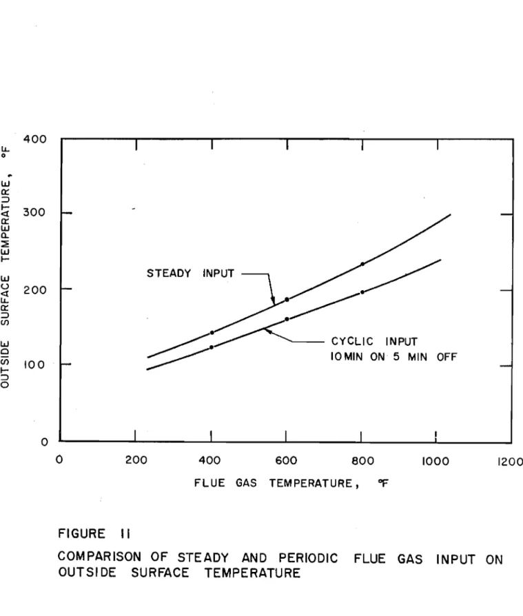
The results obtained from the computer operation with periodic input indicated. that with rapid cycling to
simulate the operation of an automatic heating appliance, the outside surface temperature reaches a constant value. At equal maximum flue gas temperature the surface temperature
obtained with a periodic input is lower than that obtained
with
a
steady input as expected. Maximum surface temperaturesobtained with a periodic flue gas input of 10 minutes on and
5
minutes off are compared with those obtained with a steadyflue gas input in Fig. 11. From this graph the periodic flue
gas input temperatures reqUired to produce the same outside surface temperature as steady flue gas input temperatures can be determined.
ACKNOWLEDGMENT
The authors grateful13r acJmowledge the advice and assistance given to this project by Dr. D. G. Stephenson and Mr. A. G. Wilson, Building Services Section, Division of Building Research, National Research Council.
REFERENCES
1. Tamura,
G.
T. andA.
G. Wilson. Fire hazard tests onsmall masonry chimneys. National Research Council,
Division of Building Research, Intenlal Report No. 202, 1960.
12
-2. McAdams, William H. Heat transmissi.on. 3rd Edi.tion,
McGraw-Hill,
1954.
"
3.
Brown, W. G. Die Uberlagerung von erzwungener undnatfirlicher kOllvektion bei niedrigen dオイ」ィウセエコ・ョ
in einem lotrechten rohr. (The superposition of
forced and free convection at low flow rates in a
vertical tube). VDI, Forschungsheft 480, Ausgabe B,
..
INTEGRATOR
O)[i
POTENTIOMETER SETTINGal.
c.FIGURE
UNIT - LUMP COMPUTER DIAGRAM OF A CHIMNEY
u,
4·0
NATURAL CONVECTION + RADIATION - -...
380 340
セNMM
• 300 260 ho = ·00675 Ts + 1·03 (APPROXIMATED) 220 180 140BASED ON AIR TEMPERATURE OF 70° F
EMISSIVITY OF WALL ·90
OUTSIDE WALL DIMENSION 16·75" x 16'75"
100
.i->:
»->
60 ... 5· 0 セ z w U u, u, W o o a: w u, C/) 3'0 z « 0::: セ セ « w 2· 0 J: a: 6·0 I <, ::::> セ CD w o C/)S
1'0 o o..c Ts OUTSIDE SURFACE TEMPERATURE, of
FIGURE 2
OUTSIDE HEAT TRANSFER COEFFI CIENT VS OUTSIDE SURFACE
FIGURE 3
OUTSIDE SURFACE TEMPERATURE VS CHIMNEY SECTION TEMPERATURE
ADJACENT TO SURFACE. 900 800 700 600 ADJACENT TO SURFACE, of 400 500 TEMPERATURE
CALCULATED FROM HEAT FLOW
EQUATION AT SURFACE - as = ·758 Gj + 17 (APPROXIMATED) 300 SECTION -? -7' -:? ,p -7' セ 100 200 aj =CHIMNEY BASED ON AI R TEMPERATURE OF 70 OF EMISSIVITY OF WALL' 90
OUTSIDE WALL DIMENSIONS -16·75"x 16·75"
K OF MATERIAL· 60 BTU /HR FT of
o
o 100 200 600 300 500 400 w o en I-::J o u, o l/I (J) w uIt
cr ::J en w cr ::J I-<f cr W CL ::2: wI-FIGURE 4
ANALOG REPRESEI\JTATION OF A CHI MNEY OUTSIDE SURFACE 1000 900 800 700 600
---.-;::::.::::::.. セNMZZZZZMMNセ
.;o.-:o-r
.
セ - hi • 4-5 x10'Tg +'-250 (APPROXIMATED) 500Tg FLUE GAS TEMPERATURE, of
W
-...
SUMMERL
POTENTIOMETER400
FLUE GAS FLOW - 100 C FM
FLUE SIZE 7"x 7"
FIGURE 5
INSIDE HEAT TRANSFER COEFFICIENT VS FLUE GAS TEMPERATURE 1·0 300 w o U) z u, 0 N l-u, 2·0 Q:: セ ::> I-CD i-e セ I-z w U u, u, 1·6 w 0 U Q:: W u, 1-4 U) z <t Q:: l- I-<t 1·2 w J:
POTENTIOM ETER
SUMMER MULTI PliER
(G 8g +1-1) 8j - 8s - 100 V - 8g FROM RELAY AMPLIFIER - 8g CIRCUIT 8g - 8S +8 5 -ej +eS FIGURE 6
ANALOG REPRESENTATION OF A CHIMNEY
セL I') I I..r---r\ r -イMiセo 11&-I 16 I
I
+100 • 1\.JI
I
7
1iHセi
セ
L - - ---".rr _ _=.J / +'00 """ r-, セ / セ +I.C. SEL セ /1 • uP )(1 / OOWN MiセO セセO / VP - VARIPLOTTER / x, - Xcoセrdinate / Y, - Y CO-ORDINATE / / ANALOG NETWORK Of / セ CHIMNEY SECTION / - ". / <, /-.
/Y
セ/
// .
: FIGURE 7ANALOG CIRCUIT OF セ SECTION OF CHIMNEY
-'M
,
ャMイセ
76 CON rFolOL..:i MAGNiTl.:CEcr INPL:TA.\4PLlTl:QE
77 」ッイセtrolセZ[ MAGNITUDE ("F INPUT I.C.
78 CONTROLS TIME ON INP'JT AMP:"ITJOE 79 CONTROL.5i TIME ON エイセpuZ r c
1000 セ 800 ui a: :J I-<t: a: 600 ui o, セ w I-OJ 400 0
It
cr :J en 200CHIMNEY TEST TEMP.
--- COMPUTER UNADJUSTED TEMP. INSIDE SURFACE MMMセ OUTSIDE SURFACE o o 200 400 600 800 1000 1200 1400
FLUE GAS TEMPERATURE, of
FIGURE 8
COMPARISON OF TEST AND COMPUTER (UNADJUSTED)
FIGURE 9
OUTSIDE SURFACE TEMPERATURE VS TIME FOR CYCLIC FLUE GAS TEMPERATURE INPUT
22 ...
-'
20 18 16.--",,-/
/-
/ /"
/'
.../ 1410 MIN ON 5 MIN OFF 10 MIN ON 10 MIN OFF I HR ON I HR OFF 2 HR ON 2 HR OFF 4 HR ON 4 HR OFF 8 10 12 TIME, HOURS 6 4 2 u, ° 180 w 160 a: :::::> I-140 c:[ a: w a. 120 セ w I-100 w o c:[ 80 u, a: :::> If) 60 w 0 40 If) I-:::::> 20 0 0 0
セ 6·0 セ u, a:: :x: <, 5·0 セ I--m
FLUE GAS FLOW - 100 CFM
.--- .---
セ
COMPUTER400 600 800 1000
FLUE GAS TEMPERATUREt of
1400 1200 GAS RADIATION FORCED CONVECTION •
----セMMMMMM
CALCULATED ---.... 200..
I--Z 4·0 w U LL u, W 0 u 3·0 a:: w u, (f) Z <r a:: 2·0 l- I--<r w :x: 1·0 w 0 (f) z 0 0 FIGURE 101
r
J セ 400 LL 0 W Q: => I-300 <t Q: W Q. セ W I-STEADY INPUT w u 200 <t LL Q: => Cfl w INPUT 010MIN ON 5 MIN OFF
Cfl 100 l-=> 0 o
o
200 400 600 800 1000 1200FLUE GAS TEMPERATURE, "F
FIGURE II
COMPARISON OF STEADY AND PERIODIC FLUE GAS INPUT ON
OUTSI DE SURFACE TEMPERATURE
¥. .セG
- MセMセセ
セZセ
,