Publisher’s version / Version de l'éditeur:
Vous avez des questions? Nous pouvons vous aider. Pour communiquer directement avec un auteur, consultez la
première page de la revue dans laquelle son article a été publié afin de trouver ses coordonnées. Si vous n’arrivez pas à les repérer, communiquez avec nous à [email protected].
Questions? Contact the NRC Publications Archive team at
[email protected]. If you wish to email the authors directly, please see the first page of the publication for their contact information.
https://publications-cnrc.canada.ca/fra/droits
L’accès à ce site Web et l’utilisation de son contenu sont assujettis aux conditions présentées dans le site LISEZ CES CONDITIONS ATTENTIVEMENT AVANT D’UTILISER CE SITE WEB.
Internal Report (National Research Council of Canada. Division of Building Research), 1956-08-01
READ THESE TERMS AND CONDITIONS CAREFULLY BEFORE USING THIS WEBSITE.
https://nrc-publications.canada.ca/eng/copyright
NRC Publications Archive Record / Notice des Archives des publications du CNRC :
https://nrc-publications.canada.ca/eng/view/object/?id=4a666d58-a965-4b53-aad1-03625a68b26c https://publications-cnrc.canada.ca/fra/voir/objet/?id=4a666d58-a965-4b53-aad1-03625a68b26c
NRC Publications Archive
Archives des publications du CNRC
For the publisher’s version, please access the DOI link below./ Pour consulter la version de l’éditeur, utilisez le lien DOI ci-dessous.
https://doi.org/10.4224/20386812
Access and use of this website and the material on it are subject to the Terms and Conditions set forth at
Design of a masonry leakage test apparatus
Plewes, W. G.
NA'rIONAL RESEARCH COUNCIL
CAN ADA
DIVISION OF BUILDING RESEARCH
DESIGN OF' A HASONHY lEAKAGE TEST APPARATUS
by
w.
G.P1ewes
A report on the apparatus and methods used by other
research organizations for investigating the problem
of masonry 1eakaee, and the factors considered in the
design of an apparatus for the Division of Building
Research
Report No.
85
of the
Division of Building Research
Ottawa
PREFACE
This Division has found in the course of field investigations and from inquiries directed to it that rain nenetration of masonry is a serious problem in
Canada as i t is in many other countries. The climate,
materials, and design and construction practices vary
from one region to another, making i t necessary for each country to carry out certain phases of rain penetration
studies on its own. There was therefore no doubt that
such studies should be undertaken as one of the major projects or the Division.
Field surveys of masonry leakage and
deteri-oration have already been made and reported. The
literature on the subject generally has been studied and
a review prepared. The next step was the planning of
laboratory work, including the selection of experimental
methods and apparatus. It is the latter Dart of this
section of the work, involVing the design of apparatus
following a careful study of the methods and equipment
used by others, which is covered in this report. A
limited series or experiments using the apparatus has
already been carried out, Bnd plans ror further testing
have been made.
Ottawa,
Augus
t
1956.
N.B.
Hutcheon,MNNMMMMMMMMMMMセセセMセセセ ..._-_....⦅MMMM⦅N⦅セ -....•_ '
-TABLE OF CONTENTS
PART A - APPARATUS AND METHODS USED BY VARIOUS OTHER
RESEARCH ORGANIZATIONS
1. American
fセ」・Brick Association at the U. S. National
Bureau of Standards -
L.
A. Palmer
2.
American Face Brick Association, National Lime Association,
Portland Cement Association at the
U.S. National Bureau
of Standards -
L.
A. Palmer and D. A. Parsons
3.
United States National Bureau of Standards - J.
W.McBurney,
M. A. Copeland and R. C. Brink
4.
United States National Bureau of Standards - C.
C. Fishburn
et al
5.
University of Minnesota - Professor J. A. Wise
6.
Detroit Edison Company - John C. Thornton
7.
Portland Cement Association - R. E. Copeland and C. C.
Carlson
8.
Department of Scientific and Industrial Research, Building
Research Station, England
9.
South African Council for Scientific and Industrial
Research - S. J. P. Joubert
10. Norwegian Building Research Institute
11. Other Organizations
PART B - FACTORS CONSIDERED IN THE DESIGN OF DBR MASONRY
PERMEABILITY TEST APPARATUS
1.
Type of Apparatus
2.
Size of Panels
3.
Type of Spray
4.
Air Pressure
5.
Temperature Control
6.
Provision for Panel Moving
7.
The Apparatus as Designed and Built
8.
Exploratory Program of Tests
9.
Laboratory Conditions
10.
Measurement of Absorption Rate
1
-DESIGN OF A HASONRY LEAKAGE TEST APPARATUS
by
W. G. flewes
Since the formation of the Division of Building Research,
architects, builders, and owners have frequently asked for advice
regarding problems of damp or leaking masonry walls.
Studies of
technical literature show that such problems occur in most
countries and a great deal of research has been devoted to them.
Progress has been made in determining the factors involved in
masonry leakage but the problem is complicated by so many
variables that present information does not, in many cases,
provide clear-cut solutions.
Since further contributions to
the technology of masonry were obviously
セ・・、・、and because some
of the exposure conditions in Canada, particularly with regard
to frost action, are more severe than in most other countries,
a program of masonry leakage investigations was given early
consideration.
When it was possible to begin active laboratory research
into the problem, one
of the first steps was to review
investi-gations made by other research organizations.
It was desirable
to take full advantage of existing information to avoid
unnecessary duplication in planning the work of this Division.
Also, since an extensive study of :nasonry leakage was most likely
to involve a variety of tests, it was possible through the
litera-ture study to profit from the experience of others with different
types of apparatus.
Phis report deals with the factors considered in the
design of an apparatus at the Division of Building Research.
\Vith this apparatus it will be possible to test small masonry
test walls which, though not large enough to be entirely
representative of a wall, will be sufficiently large to yield
significant information on the water resistance of different
unit and mortar combinations.
There will be a further advantage
in that the properties of each material in the wallettes can be
previously determined.
Unfortunately this is seldom the case
in field studies which causes some confusion in the
interpreta-tion of the performance of walls of existing buildings.
While
a thorough study of the problem will require a number of other
complementary tests on masonry materials individually and in
combination, tests with this apparatus should yield the most
direct indication of the probable performance of the materials
in an actual wall.
Similar apparatus has been used by a number of other
organizations, the only new feature in this instance being the
provision made for controlling the temperatures at the faces of
the test panel.
The test equipment of other organ izations is
briefly described in Part A of this report; Part B is a
discussion of the design of the DBR apparatus.
2
-PART A
AFPARATUS AND METHODS USED BY VARIOUS OTHER RESEARCH ORGANIZATIONS
1, American Face Brick Association at the U.S. National Bureau
of Standards - L. A. Palmer (1)
Experiments were carried out to determine the relation between the permeabilities of brick and mortar when tested singly
and in assemblages. The apparatus consisted of a metal reservoir
attached to the side of a sinGle brick or to small assemblages
(Fig.l). Water was maintained in the reservoir at constant
head and the time for moisture to appear on the opposite face recorded.
2. American Face Brick Association, National Lime Association, Portland Cement Association at the U.S.National Bureau of
Standards - L.A. Palmer and D.AoParsons (2)
A series of tests on the permeability of 8-inch brick wallettes was carried out on brick-mortar assemblages similar
to that shown in Fig.2. A head of water was applied by
impounding it in a metal frame sealed to the specimen along
the dotted lines shown. For the tests this surface was turned
uppermost. The number of leaks, the elapsed time before they
appeared, their location, -and the leakage rate per minute were recorded.
3. U.S.National Bureau of Standards - J.W.McBurneYi M.A.
Copeland, and R.C.Brink (3)
An investigation of masonry permeability was carried out by these authors in a manner very similar to that used by Palmer and Parsons.
40 United states National Bureau of Standards - C.C.Fishburn et al
The United States National Bureau of Standards has carried out a comprehensive series of permeability tests on
masonry panels and has issued a series of reports
(4,5,6
g7,8).
The test panels used were approximately40
incheswide by
50
inches high of various thicknesses. Three typesof tests were performed, "capillarityll, "heavy-rain", and
"light-rain" t e st s ,
The capillarity tests involved setting up a panel on the laboratory floor and applying water near the top of the exposure face by means of a perforated metal pipe (Fig.3). The water was allowed to run down the face in a thin sheet
at a rate of about 10 gallons per hour per lineal foot of キ。ャャセ
-
セャI
...
3
-The heavy-rain test simulated the pressure and moisture conditions set up by a wind storm accompanied by
heavy raino A pressure chamber was clamped to the exposed
face of a test panel and a pressure of 10 Ib o per square
foot above atmospheric maintained o Water was applied at
the top of the panel by means of a perforated pipe (Figo4) and allowed to run down the wall at a rate sufficient to
maintain a thin sheet of water over the whole face, usually
10 gallons per lineal foot of wall per hour0 The pressure
chamber was equipped with observation Hindows, a manometer,
a gooseneck water outlet, and a sensitive pressure-relief"
outlet. The air pressure of 10 Ib o per square inch (2 inches
of water) was considered to represent the pressure difference
across a wall which would result from a wind of 50 mopoho
The light-rain test differed from the heavy-rain test in the amount of water applied and the method of
application o About 005 gallon of water, equivalent to a
depth of approximately 002 inch per hour over the whole surface, was applied through two atomizers moving hori-zontally back and forth in front of the wallo
Newly built walls were left in the testing room for two days and then placed in a drying room for one month
before testing o The panels were also dried between tests o
Drying room temperature was maintained 30 to 40oF o above
outdoor temperatureo Walls were considered at constant weight
when the loss of weight was less than 002 per cent in seven
dayso The backs of some walls were whitewashed to show up
moistureo
Provision was made to keep the temperature of the water above the dew-point temperature of the air in the testing room to prevent condensation.
The heavy-rain test was most commonly used9 the
capillary and light-rain tests being employed as auxilliary tests to determine the relative rates of leakage under
various conditionso
Observations made during the tests were:
(a) Time required for the appearance of moisture (dampness) on the backs of the wall above the flashings;
(b) Time required for the appearance of visible water on the backs of the walls above the flashings;
(c) Time required for leakage to flow from the flashings;
(d) HaxLrnum rate of leakage, if any;
(e) Extent of damn ar-e a on the backs of the walls, including
that produced by the c8pillory riso of ュッゥウエオイセ from
water on the flashings o
An arbitrary system of rating the walls, based on
the above observations was usedo It was assumed that visible
....
4
-base of a wall, would damage plaster applied to it or injure
the interior trim. The ratinrs were as follows:
Excellent (El - No water カゥウゥ「セ・ on back of the wall (above
the flashinGs) at the end of one day. Not
more than 25 percent of the wall area damp
at the end of f1ve days. No leaks through
the wall in five days.
Good (G) No water visible on back of wall at the end
of one day.. Less than 50 percent of the wall
area damp at t he end of one day , No Leaks
through the wall in one day.
Fair (F) Water visible on back of wall in more than
three or less than 24 hours. Rate of leakage
through the wall less than one liter per hour at the end of one day.
Poor (P) Water visible on the back in three hours or
less , Hate of Le akage less than five liters
per hour at the end of one day.
Very Poor (VP) - Rate of Leakag e t.hro ugh the wall equal to, or
greater than five liters per hour at the end of one day.
5.
University of Minnesota - ProfessorJ.
A.
WiseBulletin No. 27
(9)
of the University of Minnesotadescribes permeability tests on 42- by 60-inch panels of
structural clay tileo The apparatus used was practically
identical to that devised by the National Bureau of Standards
with one or two additional features. Advantage was taken of
the fact that the tiles were hollow. The open ends of the
panels were sealed with glass so that the actual process of
leakage could be watched.. Provision was made to maintain
the relative humidity of' the testing room at
80
to90
per cent.For the first three hours of each testJ the water
was dosed with fluorescein so that even minute amounts of penetrating moisture could be ob s e r-ved und er- ultr-aviolet
light. The following data were recorded after 24=hour and
5-day testing intervals: (a)
(b)
(c) (d)
(e)
Time in hours for first dampness to appear; Time in hours for first free water to appear;
Ratio of joints showing free water to total
length of all mortar joints;
Ratio of area shcwine dampness to total area
of ー。ョ・ャセ and
=
5-The walls were セ。エ・、 by relating the above test
observations using a formula developed by Professor Wise
whI ch gave a numerical rating to each walL 'The deri vation
of the formula is not explained in the paper.
60 Detroit Edison cッュー。ョセ - John Co Thornton (10)
In a series of tests investigating the effect of brick surface texture on bond, the bricks under investigation
were built into chimneys 4 feet square p 8 inches thick and
6 courses high (Fig.5)0 Each chimney side was built of
differe nt br-Lck ,
Chimneys were cured for 30 days then water was
introduced into them and leakage measurements takeno In
some t nst anc.e s dye was placed in the water to help trace
the unbonded areaso
This method appears to have been effective for comparing the bonding characteristics of different brick
and mortar combinationso It has also been used by two or
three brick manufacturing companies.
70
PortlRnd Cement Association - rNeNcッー・ャセョ、 and C.C·Carlson(12)
An extensive series of tests was carried out by the Development Department of the PCA on 32- by 48-inch test
panels 4j
8
.and 12 inches thickp of brick j concrete masonry,and plainconcreteo The apparatus consisted of a large
propeller which sent an air blast through a duct to impinge
on the masonry test panel at 45°. Water was introduced into
the mr stream エィイッオセィ oscillating nozzles to simulate rain o
The blast was directed at 45° to the panel because of the necessity to direct rebound away from the wall and also on the assumption that rain usually strikes a vertical surface
at an angle. A 40-inch propeller was capable of producing
an air speed of 25 m,poho; a 60-inch propeller was capable
of 56 m.poh. air speed (Fig.6).
The exposure conditions used were 24 hours with a
2S-mop.h. wind and a RセMゥョ」ィMー・イMィッオイ rain intensity for the
majority of testso For very impermeable materials 12 hours
with a RセMゥョ」ィMー・イMィッオイ rain intensity and 2S-mopoh o wind
immediately followed by another 12 hours with
l2-inch-per-hour rain intensity and 25-mo p . h o wind were used.
Moisture penetration was recorded by several means:
(a) Copper electrodes were attached to the backs of
wall panels and also in the cores of hollow
units. Moisture penetration was indicated by
F
6
-(b) Notes were kept of the extent of damp areas on
the backs of walls and of the measured amounts of leakage;
(c) In some tests the presence of moisture was
detected by placing the test panels on a scale and noting the increase in weight
Wall performances were rated as follows:
Excellent - No fluid leaks or back face dampness in 24 ィoャセウ
of testing; Good
Fair
Poor
No fluid leaks and a dampening of' less than 25 per cent of the back face in 24 hours testing; Not more than 15 Ib o of fluid 1eakage nor a damp,ening of more than 50 per cent of the back face in 24 hours of testing;
15 to 50 Ib o fluid leakage and/or a dampening
of 50 to
75
per cept of the back face in 24hours testing,
Very Poor - Rapid penetration resulting in fluid leakage of over 50 Ib o and usually a general dampening of the back face
8.
Department of Scientific and Industrial Research? BuildingResearch Stationj England
In EngJand, tests have been carried out on TセMゥョ」ィ
brick masonry panels 4 feet, ャセ inches wide by
8
feet2 3 incheshigh, having rendered finisheso They are built outdoors in a
continuous row with a brick pier between adjacent panels. Water is sprayed over the whole face of a panel by means of atomizing jets without any added air pressure to simulate the
pressure due to wind. The rate of spraying is about
4
inchesper hour and records of the extent of penetration are made
at 59 15 and 30 minutes anc 12 3 and
6
hours o Any externalrendered finish that fails to prevent the penetration of
water during the period of the test is not 」ッョウゥ、・セ、
satisfactory.
90
South African Council for Scientific and Industrial ResearchSoJoPoJoubert
The South African Research Council describes an apparatus for "evaluating the resistance of walls to
penetration by rain" (II). It consists essentially of a
number of nozzles arranged to spray either masonry test
panels b feet wide and 9 feet high or actual building wall
7
-at
50
pes .. i .. and it is believed that the change in momentumof the spray particles striking the wall simulates the
pressure resulting from wind under natural conditions.. A
galvanized metal chamber was built around the spraying
apparatus to protect it from gusts of wLnd , The equipment
has been used on the sides of full-sized test houses to compare the results of tests on wall panels with the effect
on walls of エィセ same materials under natural conditions ..
The test panels are laid in rows between brick
piers (Fige
7
(b)) e10 .. Norwegian Building Research Institute - Sven De Svendsen (13)
Apparatus for testing the permeability of small test walls has been devised by the Building Research Institute of
Norway.. It was made principally to test wood-frame wall
panelsj but is also used for masonry leakage tests.. Similar
to the apparatus of the UoSoNational Bureau of Standards it consists of a pressurized chamber which is attached to
the panel to be testedo The spray method is more elaborate
however.. Water is dripped into the air streams from a bank of
air nozzles moving continuously up and down over the panel
face.. The drops are broken up and driven against the test
panel in a manner similar to rain.. The angle of the nozzle
tips is changed for each passage over the face of the panels so that the angle of incidence of the water drops is varied .. The equipment has not long been completed and there are as yet little published data ragarding its use in masonry panel
testso
II .. Other Tests
A number of other European research organizations have engaged in water penetration tests on masonry or other
types of wall constructions (13).. In most cases some sort
of spraying 。イイセョァ・ュ・ョエ is ・ューャッケ・、セ with or without an
8
-PART B
FACTORS CONSIDERED IN
THEDESIGN OF MASONRY
PER}illABILITY TEST APPARATUS FOR D.B.R.
1. Type of Apparatus
There are two main types of laboratory apparatus
commonly used for testing the permeability of masonry
assemblages: the reseryoir or chimney type where the
brick-mortar assemblages are subjected to a constant head of
water and the spray type where panels may be sprayed with
water and subjected to air pressure if desired.
The reservoir or chimney type is the simpler to
construct and appears to give good results on some aspects
of the bonding characteristics and absorption qualities of
materials.
It does not, however, permit as wide a variety
of tests on such factors as workmanship as does the spray
type.
In addition, the method of construction is likely
to be too remote from actual construction practice and the
size of the specimens is not usually sufficiently large to
be representative of the wall.
\.
The spray-type apparatus is more easily adapted to
larger specimens and so permits the testing of a wide variety
of construction types.
Furthermore the technique used in
laying the units is more likely to resemble actual practice.
Spraying of test panels with or without wind pressure is also
somewhat more closely related to the action of rain on walls
and the test data are likely to be more easily related to
natural exposure conditions.
The spray-type apparatus was chosen as the method
of test for
DBR
because of'its greater flexibility and the
likelihood of its producing the more valuable data.
2. Size of Panels
Although it is desirable that test specimens of
wall constructions be as large as possible to be representative
of actual walls there are limiting factors beyond which it is
impracticable to go.
Preliminary calculations indicated that
a test panel
3
feet 6 inches wide by
4
feet 6 inches high
would give a suitable compromise between size and weight.
A
12-inch solid brick wall of even these dimensions might weigh
as much as 1800 lb. and if it is to be handled with care
requires special equipment to move it.
With larger panels
both the moving and testing equipment become increasingly
cumbersome.
Increased size of panels and equipment also
30 Type of Spray
For the spray-type apparatus there is a choice of
spraying the test panels at the top so that the セ。エ・イ flows
down the face in a thin sheet or of spraying or blowing the
water over the whole panel face to simulate raino The
first-mentioned equipment may be used to determine the relative resistance to water penetration of different masonry panels
under the test 」ッョ、ゥエゥッョウセ but might not ァゥセ an absolute
indication of their behaviour under natural raino Bowever,
it should be possible to control the conditions fairly
closely and obtain useful information regarding the セャ。エゥカ・
importance of the numerous factors involved in the masonry leakage problem.
Where apparatus is made to simulate rain by spraying
or blowing water uniformly over the panel face9 it is open to
question whether the results are any more reliable as an
indication of wall performance under natural weather conditions or whether they again permit only a relative comparison of
panel performances. After careful study of weather data,
some investigators have found it necessary to make some
assumptions in deciding: on their test c cnd Lt.Lon s , 'I'hl s is
usually caused by the difficulty in actually duplicating
rain or to the desire to accelerate the test. For instance,
Copeland and Carlson HQRIセ who used the apparatus shown in
Fig Vセ made a study of climate data in 11 cities for a
20-year periodo They discovered that of 1759 rain storms of
I-inch or more in 24 hours only 36 were accompanied by an
average wind velocity greater than 25m op.h o Such heavy
rains could be continuous for 24 hours or intermittent for
several days. In actual tests these investigators used a
wind speed of 25 mop.h. and an intensity qf 2i inches per
hour. which, tests indicated, was roughly equivalent to a
i-inch rainfall over a much longer periodo This may be true,
but it is a departure from duplicating actual rain conditionso In some cases also the simulated rain intensity was increased
to 12 inches per hour o Observing Figo69 it is a question
also whether the wind velocity and air pressures at the
restricted outlet of the duct duplicated natural conditions o At the Norwegian Building Research Institute (13) there is no doubt but that the method of blowing water onto
the panels ゥセ a fairly close duplication or driVing rain o It
has the advantage of being arranged to make it possible to alter the angle of incidence of the water particles which
would be important in testing frame construction, window
details, etco, for which it was mainly designedo In their
standard test, wate
2
is delivered onto the panel at the rateof
8
to 10 litres/m /hro 9 and the applied air pressure iskept constant at 50 mm o of water. These conditions were
assumed after careful study to correspond to the ultimate
10
-to ac c e Le r-e
t
e the test i t ws.:::: found de sf.r abLe to increasethe s upcr-e pr-e s sur-e to
75
mm, of Hater. This is a departuref'r-oru normal c cndi tions and is ccnsidered to be more severe
than the standard test. Some tests have been carried out at
the S8.me Institute by rl.IDning Hater down the face of plastered
masonry p aneLs in a thin sb.e et r-at.her- than spraying it. It
has been observed that, "No noticeable cUfference in result s
was discernible with the two methods, 2nd there is reason to
believe that the effect of drops is not significant for walls of this type".
It is known that for most masonry walls the first
rapid absorption is satisfied 'dithin 8- few minutes and
there-after in normally heavy rains thG water セッ・ウ in fact form a
thin film on the face of the wall (1,
13,
14).
Not onlydoes the water actually falling on the area of wall in question contribute to this film but also the run off from
other areas of wall above it. For this reason and because
any apparatus providing an artificial rain is ant to be of
doubtful success in actual dupli0ation of ョ。エuQセ。ャ conditions
i t was decided to incorporate in the DBR test apparatus a
method of spraying water at the セッー of the test panels and
allowing i t
t
o .un down in a thin film und er- a constantsuper-pressure. 'I'bes e condi tions c an be fairly ac cur-at eLy
controlled Bnd should be suitable for determining the factors governing the relative water permeabilities of panels made
of different materials, types of c on st r-uct Lon , and wcr-kmanah Lp ,
It then remains to correlate the data obtained with the behaviour of actual structures and climates, possibly using
some type of outdoor exposure test on selected materials and constructions in several locations.
4.
Air PressureWhere a masonry wall has no cracks or openings in its
face, penetration \rIill occur through the pores of the material,
principally by capillarity
(13, 14,
151.
The effect of Hindor particle impact will have a relatively minor effect. Where
large pores, cracks, or fissures extend through the wall:
wind pressure has a major effect on the penetration
lI3).
For this reason i t was thought that the apparatus should have provision for the appllcation of air pressure to the sprayed face of test panels.
5.
Temperature ControlAlthough tests on masonry panels have been made in a
number of places there is no r-ec or d of
t
e sts DeiEE: made underany but isothermal conditions. The influence of exterior and
interior temperatures on wall permeability has not been
investi-gated in tests of this type. T!:o·,Tlpt"')rcitun3 ST'ndients may be of
some importance to both the migration of moisture through a wall and the amount of drying that takes place i'clloHing
successive periods of rain. It was proposed, therefore, to
prOVide means of controlJing temperature on one or both sid.ss
11
-of the test panelso This arrangement was envisaged as
consisting of a panel sealed between temperature-conditioned snray chambers but insulated from direct contact with the
supoorting metal framework. Besides allowin7 for control of
the temperature gradients i t would be possible to subject
wall panels to cycles of freezing and thawing between sprayings.
6.
Provision for Moving The PanelIt was obvious from the outset that some method would have to be devised for transporting the panels to and from the test apparatus or to a possible exposure site o
70
DBR Apparatus Design and CO,nstructionFigure
8
shows the DBR masonry permeability testapparatuso The panels are built on a slab of rigid,
foamed-plastic insulation
6
inches thick. For testing they areplaced in a steel framework having means of clamping similar
slabs of insulation on the sides and top of the paQel. It
ゥウセ therefore, isolated from any wood or metal part by at
least
6
inches of insulation.The frame is provided with casters so that it can
also be used for moving panels short distanceso For
trans-porting them longer 、ゥウエ。ョ」・ウセ such as to an exposure site,
provision has been made to attach two automobile trailer wheels and a suitable hitch to the frame so that i t can be towed by a truck.
The spray chambers consist of boxes made of special
sheets of extruded aluminum having provision for carrying
copper イ・ヲイゥァセイ。エゥッョ coils. Outside this is a layer of
fibre-glass insulation covered with plywoodJ and then a
copper sheath. The chambers are designed to rest on steel
frames with casters and are clamped to the panel insulation
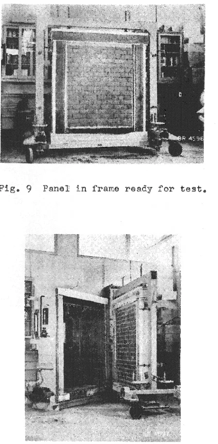
during tests. For early tests a temporary
plywood-and-copper spray chamber without cooling coils
was
used. (Figs.99 10 and II).
Air pressure is supplied from the laboratory
compressed air service through a pressure regulating device,
with a water manometer used to measure pressure. Water is
pumped from a storage tank through a meter to the spray device which consists of a perforated copper tube placed to deliver small streams of water at the top of the panel. Water reaching the bottom of the panel is deflected into
a trough by a flashing from where it drains into the stora.ge
tank for re-circulation. Water passing through the panels
in sufficient quantity to run off the back face is collected by another flashing and drained into a pan for measurement.
12
-8.
Exploratory Program of Tests
A series of panels was planned to test the apparatus
under isothermal conditions and provide exploratory data.
Test
conditions were more or less arbitrarily chosen.
The rate of
water delivery was set at 0.5, gallon per minute.
Experiment
showed that this was about the minimum necessary to provide an
unbroken film of water over even the most absorptive panels.
The atr pressure within the spray chamber was set at
13 lb. per square foot of a panel area which is equivalent
to the velocity pressure of a 70-m.p.h. wind on a flat surface
30 feet from the ground.
This is a severe condition but not
impossible since the maximum recorded gust speeds over most
of Canada are over 100 m.p.h. and on high buildings or on the
sea coasts winds of high velocity are not uncommon.
A high
air pressure was chosen purposely to produce readily
recog-nizable results with the idea of revising it for future tests
in the light of test observations.
It is not believed that
a high wind is necessary to produce masonry leakage but tests
show that the rate of leakage is sensitive to increases in air
pressure.
When the initial series of tests is completed the
experience and data obtained will assist in settinr, up the
test conditions to be used for the main program of-tests.
The following are some factors that will have to be reviewed:
Ca) Air pressure - Although the test conditions do not duplicate
natural exposure the air pressures used should approximate
actual wind pressure.
It will probably be desirable to
set this as high as practicable to reduce the testing time;
(b) Water spray rate -The water should form an unbroken film
over the face of the panel so that the opportunity for
leakage will be the same for all panels.
Consideration
will have to be given to the effect of film thickness,
if any.
The control of water temperature in temperature
control tests will be important;
(c) Methods of rating the Eerformance of test panels
-Methods of panel rating and failure criteria will have to
be decided upon in detail.
The initial series of tests may also indicate some
desirable changes in the design of the apparatus although
at present no major changes appear necessary.
9.
Laboratory Conditions
Since the panels are to be water sprayed on one face
and exposed to the laboratory air on the other, the desirability
of controlling the relative humidity of the laboratory air will
13
-is low, that in cases of slow penetration, mo-isture may
evaporate on some plane below the panel surface and not
be visible.
On
the other hand it may at times be
desi-rable to control the relative humidity of the laboratory
air to avoid condensation on the back of a cooled panel.
10. Heasurement of Absorption Rate
When masonry units and mortar are dense and
non-absorptive, water penetration of a wall, if any, is likely
to occur through cracks or unfilled joints and the amount
of water actually absorbed by the materials is not
signi-ficant.
In other cases where the masonry units absorb
relatively large quantities of water, penetration of the
wall may not beGin until the absorption capacity
ッセthe
materials is satisfied, that is, the wall acts as a
reser-voir
(14, 15).
It may at some time be desirable in investigations
of this latter type of wall to measure the amount of water
absorbed in a given time.
This might be done either by
weighing the panels periodically or by metering the spray
and leakage water to obtain a mass balance.
The
develop-ment of this feature of the apparatus is under
considera-tion, but some exploratory testing is needed.
- - - -M M M M セ M セ
14
-HEFEHENCES
1.
Palmer, L. A.
Water penetration through brick-mortar
assemblages.
American Face Brick.Association,
Rock Products, Vol.
34i
November 21, 1931
2.
Palmer, L. A. and D. A. Parsons. Permeability tests of 8-inch
brick wallettes.
Proceedings of the 37th
Annual Meeting A.S.T.M., Vol. 34, Part 2. 1934.
3.
McBurney, J. W., M. A. Copeland, and R. C. Brink. Permeability
of brick-mortar a s se mb
Larees ,
A.S.T.M. Pr-oc ; :
Vol. 46. 1946
-4.
Fishburn, C. C., D. Watstein and D. E. Parsons. Water
permeability of masonry walls.
National
Bureau of Standards, Building l-1aterials and
Structures Report BMS 7.
October 8, 1936.
5.
Fishburn, C. C.
Effects of wetting and drying on the
permeability of masonry walls.
National
Bureau of Standards, B-'ilding I'1ateria1s and
Structures Report
BMS
55,
September 18, 1940.
6.
Fishburn, C. C., and P. H. Petersen. Effects of heating and
cooling on the permeability of masonry walls.
U. S. National Bureau of Standards, Building
Materials and Structures Report BMS 41.
January 11, 1940.
7.
Fishburn, C. C., D. E. Parsons, and P. II. Petersen.
Effect
of outdoor exposure on the water permeability
of masonry walls.
National Bureau
.01'Standards,
Building Haterials and Structures Heport BNS 76.
August 15, 1941.
8.
Fishburn, C. C.
Water permeability of walls built of masonry
units.
National Bureau of Standards, Building
Materials and Structures Report BMS 82.
April
15, 1942.
9.
Wise, J. A.
Water permeability of structural clay tile facing
walls.
University of Minnesota Institute of
Technology,
Bulletin No. 27.
August 18, 1948.
10.
Thornton, J. C.
Relation between bond and the surface physics·
of masonry units •. Detroit Edison Company,
published in American Ceramic Society Journal.
April 1953
11.
Joubert, S. J. P.
A method for evaluating
エィセresistance of
walls to penetration by rain.
South African
Council. for Scientific and Industrial Hes ea r-ch ,
· 1.5
-12. Copeland, H. E., and C. C. Carlson. Tests of the resistance
to rain penetration of walls built of masonry
and concrete. Journal of the American Concrete
Institute, Vol.
36.
November1939
13.
Svendsen, Sven.D. Driving rain, experimental research on theresistance of external walls against rain
penetration. Norwegian Building Research
Institute, Oslo.
19.54
Butterworth, B. Bricks and modern research.
and Son Ltd., London.
1948.
Crosby, Lockwood15.
Fitzmaurice, R. Principles of modern building, Volume1
-walls, partitions and chimneys. D.S.I.R.,
SINGLE BRICK, 2 BRICK ASSEMBLAGES OR 4 BRICK ASSEMBLAGES
FIGURE 1
METAL RESERVOIR ATTACHED TO ASSEMBLAGE WITH SUITABLE CLAMPSr---._ -WATER LEVEL
JO I NTS SEALED WITH
セM SPONGE RUBBER AND
RUBBER CEMENT
BRICK MASONRY ASSEMBLAGE
PERMEAB ILITY TEST APPARA TUS
(PALMER1)FIGURE 2
WALLETTE FOR WATER PERMEABILITY TEST
(PALMER &
PARSONS
2 )PANEL EDGES
pargedセr-PERFORATED SPRAY
;)
PIPE
,,0
MASONRY PANEL
FLASHING
TO
COLLECT
leakaセ
FIGURE 3
"CAPILLARITY" TEST AT U.S. NATIONAL
BUREAU
OF STANDARDS
(FISHBURN, WATSTEIN AND PARSONS 4)
SPONGE RUBBER SEAL:s MASONRY PANEL FLASH I NGS TO <, COLLECT LEAKAGE "'-カ]イZZAセ
FIGURE
4
PRESSUR IZED CHAMBER SPRAY PIPE
SCHEMATIC DRAWING SHOWING
THE
TYPE OF
APPARATUS
USED FOR
THE HEAVY-RAIN
TEST
AT
THE
U.S.
NAT IONAl
BUREAU
OF STANDARDS
(FISHBURN. WATSTEIN AND PARSONS 4)
FIGURE 5
CAULKING
COMPOUND 4 F'TOF DIFFERENTSQUARE CHIMNEY. EACHBRICK. SIX SIDE COURSES HIGH
BRICK CHIMNEY USED BY THE DETROIT
EDISON
COMPANY
(THORNTON 10)
TEST PANEL
FIGURE 6
TYPE OF APPARA TUS USED BY THE PORTLAND CEMENT
ASSOC I A T ION (COPELAND AND CARLSON '2)
GALVANIZED IRON SHIELD
SPRAY PIPES AND NOZZLES FIGURES 7 A &B TEST PANEL OR ACTUAL WALL FIG 7A MASONRY PANEL} FIG 7B OF APPARATUS FOR SCIENTIFIC
SCHEMATIC DRAWING SHOWING THE TYPE
USED BY THE SOUTH AFR I CAN COUNC I L
AND INDUSTRIAL RESEARCH (JOUBERT")
0.6./1. IlEPO/lT 6$ LA"'OQ.ATOIlY A/Q UNE PQESSUJZ£ Ill:. G.lJLATOQ
!'1F'c. iBャnセf ----FQOIW .''0 flITCH -MMMMセaャjtッBBッtョOᆪ CI10SS5 ....Q Oセ - TO,.lING セ - - - ----ALl/MINIUM PA.WZLS "'ND COOL/Wr; coGlセ
FJI!JIle. GLA.IU· INSULATtOW
GOセN pL Yh/OOD
coppセT COVZJ:l.IWG
TQ"'P A."'O lfirOQ"'fi,L T"'NI/ PIPE. MMMMMLセセQャ ---", II Bセi SOFT /WSLiLATlON --111"0 inセャjlatioGB ヲ]セセMセMMMMMMᆳ ゥセOZ
---SE.CTION A-A I i ! [jゥjセ}BセM
-It-
セ
nJ;- --",," ""-"""'.
セ
MMMMMMMMLloGセ
"'<TLOL
I セlMV⦅MM _ _FIlOM ヲ[toqaBセ TANI( \-.<-siHセtch SHO,J''''G TEST. FRAME "ITH TRAILER whセel attachセd
'",
.;,
jセイ
/-611 ... CKET FOQ tセaNOleq l'!IUt-L A.TT.ACflMENT
cL ...",ps
---£YE. boltセ FOI1 HOIST/AIr; Oil 1v'£IG-HIAlfi, FI1AME A.IJO PAWEL
/
!
, L-fAllfiULATIOJol CL"'MP£D ᆪPセᆪU OF p,J,AlE.L t-NOT£. ; A 11 1 , 11 1---.-J __セ⦅」⦅セセ⦅L⦅M
ill
uhセMセL」""
AZjュiセjil
...
jセェ
0
.-::---:::.=---B Sf-eTION B-B I Zセi."
_,I -..'!iセteeNl Tt.ST FQ..AME PROYIOE.5- /.U,I,NS OF (LAMPI!JG- /Al5l/LAT/ON TO P,I,NLL loエ[QNU⦅セ
...セッ iセ aャNセo lJSEO FOI2. TRA.Al5POIlT"IAl6 \
セセオ \
"
jャセ i-L,' :[1 F='=1 ゥセZ I--.=:J ゥAセMセBセLャt , , iHセ 0 ! lfiPI1A.Y chaヲiNQャA^セq CL,AMPED TO MMMMセGLセLGLコLセMM[[ZMMBOMャLイLL , : ' . 'LGセ LGエGZMGZBMMLセUQO F ...a OF tセセt pセBeNl 8'1 ME.ANS 'l --j" , ' , '-er--OF 'y'Z'BOLTE CLAMPfN(; FIZAME = ; . - ::,r 11;1 II '_:;,< \ "_ =--= "
セGZZイセsct oセHOセZaエZZャjセセtiZwaNォeN ---"";セ⦅⦅ L_:<\-- ' , .<y , : , 'c:
MGMMMMMZセL セ セゥ
TO セMセG iセZZ
l;:}lud-
JJ
セigureN
e
TYPICAL MA60J./QV rs et panセl 5WOI"lN /"I/P4 TZMP£QA.Tl/D.£ contqollセd CJlA,.,tJe,1:I CLA.NlPZD TO DIIZ FAce ONLY. PROVISION IS /t4AOE. FOQ. CLAmpOjッiセ A. Uセcowd CUA.M6ED. TO THZ OPP05/TZ FACI. ""NI.IoJ d・NセOrイNdN
JACK SCQ.f. •.I!> FOI1 QAISING LO ...fI2IWG- AIJO l.EIILL/NG-TZST pANZLS
1
in frame
エ・ウエセFigG 10 View showing interior of
temporary spray chamber, water pump,
water flow meter
1manometer, air
pressure regulator and a test panel
about to be installed for test"
fゥァセ 11 Panel clamped to spray chamber