Cryogenic Surface Electrode Ion Traps with
Integrated Superconducting Microwave
Resonators for Polar Molecular Ion Spectroscopy
by
MASSACHUSETTS INSTItUTE
Paul Bogdan Antohi
OF TECHNOLOGYM.S. Physics
OCT 3 1 2011
Case Western Reserve University, 2004
LiBRARIES
S.B. Physics
Alexandru loan Cuza University, 1999
Submitted to the Department of Physics
in partial fulfillment of the requirements for the degree of
Doctor of Philosophy in Physics
at the
MASSACHUSETTS INSTITUTE OF TECHNOLOGY
June 2011
@
Massachusetts Institute of Technology 2011. All rights reserved.
//7
A uthor ... .. ... . . . .. ... ...Department of Physics
May 23, 2011
Certified by ...
..
..
.... ...
Isaac L. Chuang
Professor of Physics and
Professor of Electrical Engineering an Computer Science
)
/,
/
j
J
Thesis Supervisor
Accepted by ...
. . . .
Acpeby'Krishna Rajagopal
Professor of Physics, Associate Head for Education
Cryogenic Surface Electrode Ion Traps with Integrated
Superconducting Microwave Resonators for Polar Molecular
Ion Spectroscopy
by
Paul Bogdan Antohi
Submitted to the Department of Physics on May 23, 2011, in partial fulfillment of the
requirements for the degree of Doctor of Philosophy in Physics
Abstract
Trapped cold molecules open the possibility of studying ultracold chemistry and as-trophysical processes in laboratory settings. Their rich internal structure also makes them suitable for quantum information manipulation or for tests of fundamental laws of nature. These experiments require precise control over the molecular internal de-grees of freedom. There are few present proposals for trapping and cooling molecules. One proposal is based on confining neutral polar molecules in DC Stark shift traps, but this approach presents some issues. An attractive alternative is to confine polar molecular ions in RF Paul ion traps, which is the focus of this thesis.
The objectives here are to develop the theoretical models and to devise the ex-perimental components and methods to investigate the coupling of polar molecular ions' rotational states to the microwave radiation. The new approach presented here is based on co-trapping Sr+ atomic ions together with SrCl+ molecular ions in a cryo-genic surface electrode RF ion trap and on using the coupling of the molecular ion's rotational states to an integrated superconducting microwave line or cavity either as a cooling method or for precise rotational spectroscopy.
The first part of the thesis describes two theoretical methods for observing the coupling of the microwave radiation to the rotational levels of a molecule. The first method proposed is based on the enhancement of the molecular rotational transi-tion rates by the co-trapped molecular-atomic ions Coulomb collisions. The second method is based on microwave cavity assisted heating or cooling of the molecular ions. The second part of the thesis presents the development of a cryogenic surface electrode RF ion trap with an integrated microwave transmission line/resonator. The ion trap is operated in a 4.2 K closed cycle cryostat.
Thesis Supervisor: Isaac L. Chuang Title: Professor of Physics and
Acknowledgments
This thesis would not have been possible without the support of many people at MIT. I thank my advisor, Professor Isaac Chuang, for his tremendous support. Working in his lab has been an invaluable learning experience. I appreciated the opportunity to work on both the theoretical and experimental aspects of my project. I am also grateful to Ike for his continuous efforts to secure the funds essential for the lab. Furthermore, I really appreciate his high standards in the communication of scientific information, as they have been very valuable in my training to write and speak about physics. I also want to thank all members of my committee, including Professor Vladan Vuletic and Professor Pablo Jarillo-Herrero, for their great insights and feedback on my project.
I owe a lot to my lab mates. I thank Waseem Bakr for bringing me up to speed on the workings of the lab and for his assistance in setting up the first cryogenic ion trapping system in the lab. Robert Clark has been a great colleague and friend to have around. I thank him for his design of the trap on which I made the first forays into my project. I appreciate our conversations over the years. His humor has lightened many long days of work in the lab. In addition, I learned a lot about the hardware side of lasers through my conversations with Jaroslaw Labaziewicz and by studying the lasers that he built. David Schuster was instrumental in our collaboration on setting up the first stages of the experiment described in this thesis. I thank Stephan Schulz for his help in investigating the first Nb based superconducting microwave resonators in our lab. I am very grateful to Yufei Ge for her help on the trap wirebonding and in fabricating the traps used at the beginning of this project, and to Adam McCaughan for building the later Nb surface electrode ion traps, which were essential for this project. I thank David Meyer for his help in setting up the microwave delivery components. I thank Anders Mortensen and Arolyn Conwill for their help in a series of calculations and experimental measurements of the cryostat heat loading.
I thank my mom and dad for their encouragements and tremendous support from the early beginnings of my interests in science. I dedicate this thesis to them.
Contents
1 Introduction 15
1.1 Cold polar molecules. . . . . 15
1.1.1 Why polar molecular ions? . . . . 15
1.1.2 Cooling of neutral and ionic molecules . . . . 16
1.2 Contributions of this work . . . . 17
1.2.1 Theoretical work . . . . 18
1.2.2 Experimental work . . . . 19
1.3 Thesis outline . . . . 20
1.4 Co-workers contribution and published results . . . . 21
2 Ion traps with integrated microwave resonators 23 2.1 RF ion traps with integrated microwave resonators . . . . 23
2.1.1 Slot line RF ion trap (Azkaban traps) . . . . 24
2.1.2 Strip line RF ion trap . . . . 25
2.1.3 CPW line RF ion trap (Giants traps) . . . . 25
2.2 Theory of ion trapping in RF quadrupole traps . . . . 26
2.2.1 Mathieu equations and the adiabatic approximation . . . . . 27
2.2.2 Boundary element method for numerical simulation . . . . 32
2.3 CPW microwave resonator . . . . 37
2.3.1 Classical description of CPW microwave resonators . . . . 37
3 Dynamics of co-trapped atomic and polar molecular ions in the
presence of electromagnetic fields 41
3.1 Laser cooling of systems with A level structure . . . . 41
3.2 Rotational levels of diatomic heteronuclear molecules in E electronic ground state... . . . . . . . 46
3.3 Collisional assisted microwave heating . . . . 48
3.3.1 Collisional excitation cross section . . . . 49
3.3.2 Collisional excitation reaction rate . . . . 55
3.3.3 Collisional enhanced heating rate . . . . 57
3.3.4 Numerical evaluation of collisional enhanced heating rates . . 61
3.4 Cavity assisted microwave heating . . . . 63
3.4.1 Normal modes of a one dimensional harmonic ion trap . . . . 64
3.4.2 Circuit QED description of CPW microwave resonator . . . . 69
3.4.3 Quantum Hamiltonian for a system of one molecular ion and one atomic ion co-trapped in the presence of a microwave cavity 72 3.4.4 Microwave cavity assisted side band heating rates . . . . 74
3.4.5 Numerical evaluation of cavity assisted side band heating rates 84 4 Experimental Apparatus 86 4.1 Experimental Setup . . . . 87
4.1.1 The closed cycle cryostat . . . . 87
4.1.2 Trapping potentials delivery components . . . . 91
4.1.3 M icrowave source . . . . 92
4.1.4 Im aging optics . . . . 94
4.1.5 Laser system s . . . . 97
4.1.6 Vacuum system and heat load . . . . 99
4.2 Atomic and molecular ion production through laser ablation . . . . . 99
5 The ion traps 104 5.1 3D ion traps ... ... 104
5.1.2 Strip line ion trap (plate and wire) . . . . 106
5.2 Nb surface electrode ion traps with superconducting CPW resonator (G iants traps) . . . . 108
5.2.1 Trap geometry . . . . 109
5.2.2 Trap design and trapping properties . . . . 110
5.2.3 Trap fabrication and packaging... . . . . . . . 113
5.2.4 Trap issues: ablation charging and electrode arcing . . . . 115
5.3 Trapping and detection of molecular ions . . . . 117
6 Conclusions and outlook 127 A Boundary element method code for rf ion traps numerical modeling145 A.1 Trap geometry . . . . 145
A.2 Dc potentials and rf electric field grid... . . . . . .. 149
A.3 BEM .... .... ... . . .. . . . . . . ... .. .. .. .. . 150
A .4 Trap analysis . . . . 172
B Numerical evaluation of collisional enhanced heating rates 180
List of Figures
2-1 RF ion trap with integrated microwave slot transmission line (Azkaban trap series). . . . . 24 2-2 Rf ion trap with integrated microwave strip transmission line. The
pinhole in the microwave electrode allows for ion imaging. . . . . 25 2-3 RF ion trap with integrated microwave coplanar waveguide (Giants
trap series).. . . . . . . . 26 2-4 Microwave electric field distribution above a CPW transmission line. . 26 2-5 RF electric field distribution in a surface electrode ion trap. The ions
are trapped at the RF field null (red dot). . . . . 27 2-6 Stability map of Mathieu's equation (stable regions are shaded). . . . 29 2-7 Example of a pseudopotential for a surface electrode trap obtain by
numerical modeling. . . . . 32 2-8 CPW based microwave resonator. . . . . 38 2-9 CPW microwave resonator quality factor versus its length for a
radi-ation of angular frequency w = 2 r 6.52 x 10⁹ Hz. Resonator
charac-teristics: specific impedance Z = 50 Q, specific capacitance c = 153 pF/m, specific inductance 1 = 383 nH/m, central electrode width 400 pm, and coupling capacitances Co=1.53 x 10⁻¹⁴ F. . . . . 40
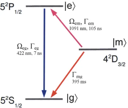
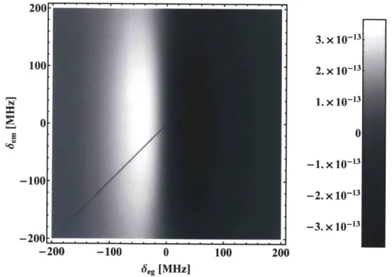
3-1 A level structure in 88Sr+ ion. . . . . 42 3-2 Damping coefficient a vs. laser detunings for SSSr+ ion cooled on 422
ni transition with Qeg = Qem= 1MHz. For 6eg - 6em the damping
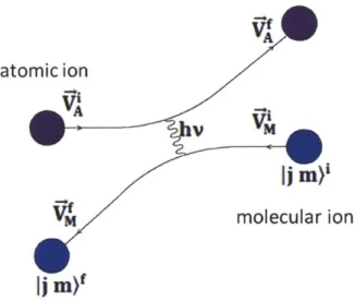
3-3 Schematic of the collisional assisted microwave heating experiment. A mixed ion cloud of Sr+ and SrCl+ is trapped in a surface electrode ion trap above a CPW microwave transmission line. . . . . 48 3-4 Schematic of the angular momentum transfer between an atomic ion
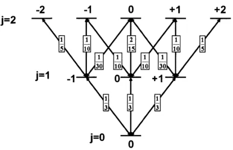
and molecular ion during a Coulomb collision. Internal angular mo-mentum of the molecular ion can be transferred from or to the relative motion of the two ions. . . . . 49 3-5 Transition probabilities between the magnetic sublevels of the
rota-tional levels j=0, 1, and 2. . . . . 58 3-6 Population inversion as function of the ion cloud temperature, in the
presence of microwave radiation tuned to resonance with the
j
= 0 ++j
=1 transition (Am = 0). The other parameters are as in text:EM = 1500 V/m, nA = 1.25 x 10¹⁴ M-3. . . . . 62 3-7 Heating rate per molecular ion as function of the ion cloud temperature,
in the presence of microwave radiation tuned to resonance with the
j
0 ++j
= 1 transition (AM = 0). The other parameters are as intext: EM = 1500 V/m, nA = 1.25 x 10¹⁴ M-3. . . . . 63 3-8 Schematic of the cavity assisted microwave heating experiment. An
ion crystal composed of one Sr+ ion and one SrCl+ ion is trapped in a surface electrode ion trap above a CPW microwave cavity. . . . . 64 3-9 Overview of side band microwave cavity assisted heating for a system
of one molecular ion and one atomic ion. The molecular and atomic ions are co-trapped in a RF ion trap in Lamb-Dicke regime and in the presence of a microwave cavity. The first rotational transition of the molecular ion is pumped on the first red motional sideband, while the microwave cavity is tuned to the natural rotational transition frequency. In the presence of the microwave cavity the spontaneous decay rate of the molecular excited rotational state is enhanced by the P urcell effect. . . . . 64
3-10 System of right-handed cartesian coordinates for analyzing the normal modes of a one dimensional harmonic ion trap. The ion motion is confined to y axis only, and the microwave field is directed along the z
ax is. . . . . 65 3-11 Center of mass mode and breathing mode phonon numbers time
evolu-tion constant [A+ (wi) - A_ (wi)] as function of the applied microwave field frequency. Negative values signify cooling, while positive values indicate heating. Physical parameters of the trap are provided in text. 84
4-1 Principal components used in the design of the cryostat system. The fluorescence light is collected through the bottom viewport. . . . . 88 4-2 Schematic cross section through the closed cycle cryostat. The imaging
optics anchored onto 4 K radiation shield is exposed directly to the 300 K radiation from the bottom viewport. (Not to scale) . . . . 89 4-3 View of the closed cycle cryostat working chamber. The rest of visible
components are described in Figure 4-2. . . . . 90 4-4 Vibration power spectrum of the closed cycle cryostat sample holder.
The vibration power spectrum was measured with the cryostat com-pressor turned off (gray curve) and on (black curve). The inset shows the lower part of the spectrum where the fundamental and higher har-monics of the cryocooler expander head vibration can be distinguished. The spectrum has 2.5 kHz bandwidth and 0.17 Hz resolution. .... 91 4-5 Ion trap carrier ensemble. To insure good thermal contact the unused
pins of the socket are soldered to the copper plate base. The pedestal is mounted directly on to 4.2 K baseplate. . . . . 92 4-6 Diagram of the main components involved in the production and
de-livery of the microwave signal to the ion trap. All the elements present in the setup have 50 Q characteristic impedances. . . . . 93
4-7 For good thermal contact the copper-copper microwave coaxial cables are tightly wrapped around a) 40 K shield and b) 4 K stage of the cryostat. . . . . 95 4-8 Imaging setup schematic. The fluorescence signal is collected by an
aspheric lens placed at 22.5 mm from the ions. The focused light is dived by a 30/70 beam splitter and collected by a CCD camera and a photon counting PMT. . . . . 96 4-9 Detailed chart with the heat loads on the two cooling stages of the
closed cycle cryostat. . . . . 98 4-10 Temperature vs. heat load for the two stages of ARS GMX-20B
cry-ocooler (provided by the manufacturer). . . . . 100 4-11 The light produced by a frequency tripled Nd:YAG laser is focused to
a 0.5 mm spot size onto the ablation targets. . . . . 101 4-12 Example of a set of three ablation targets: (from left to right) SrCl2
compressed powder, 0.5 mm thick SrTiO3 crystal, 1 mm thick SrTiO3
crystal. The ablation targets are bonded to the copper carrier with cyanoacrylate based adhesive. . . . . 102
5-1 Example of a two layer ion trap with integrated microwave slot line. The copper electrodes are patterned on a 20 mil thick Rogers R04350B laminate. The distance between the RF/MW electrodes is 0.8 mm, and the two electrode layers are separated by a 0.127 mm thick PTFE spacer. 105 5-2 Slot line ion trap geometry and the numerically simulated trapping
pseudopotential. The red dot marks the trapped ions location. . . . . 106 5-3 Cross section through the trapping pseudopotential for the slot line ion
trap. The contours represent equipotential surfaces with their values indicated in units of eV. The red dot marks the trapped ions location. 107 5-4 Example of a "5Sr+ ion chain trapped in the slot line ion trap. The third
ion from the left is non-fluorescent (dark ion). The mean separation between ions is - 10 pm . . . . 107
5-5 Ion trap with integrated rectangular microwave strip line: a) the bot-tom layer containing the ion trap electrodes, and b) the ion trap with the transmission line installed. . . . . 108 5-6 Ion trap with integrated rectangular microwave strip line geometry and
the numerically modeled trapping pseudopotential. The red dot marks the trapped ions location. . . . . 109 5-7 Geometry of the ion trap with integrated cylindrical microwave
trans-mission line and the numerically modeled trapping pseudopotential. The red dot marks the trapped ions location . . . . 110 5-8 Ion trap with integrated cylindrical microwave transmission line. A
1 mm diameter silver rod placed 1 mm above the ion trap acts as microwave electrode. The ion trap is mounted such that the plane of the trap makes a 30' angle with the imaging axis. . . . . 111 5-9 A surface electrode ion trap with integrated microwave coplanar
waveg-uide. In this example the ion trap contains eleven DC control electrodes and two RF trapping electrodes. In order to allow for cooling lasers access the ends of the microwave transmission line are displaced from the ion trap longitudinal axis.. . . . . . . . . 112 5-10 Simplified geometry for the surface electrode ion trap. The letters
indicate the dimensions used in computing the approximate solution. 113 5-11 Example of Nb surface electrode ion trap with integrated microwave
CPW transmission line. The ion trap electrodes are identified in Figure 5-9. The gaps between electrodes are 25 pm wide, the RF electrodes are 0.7 mm wide, and the central CPW electrode is 0.6 mm wide. . . 113 5-12 Chain of five 88Sr+ ions trapped in the Nb surface electrode ion trap
with integrated microwave CPW transmission line. The mean separa-tion between ions is pm. . . . . 114 5-13 Geometry and trapping pseudopotential for the Nb surface electrode
ion trap with integrated microwave CPW transmission line. The red dot marks the trapped ions location. . . . . 114
5-14 Nb surface electrode ion trap x0z cross sections for: a) pseudopotential, and b) microwave electric field absolute value. The microwave electric field is orthogonal to the lines of constant value. The red dot marks the trapped ions location. . . . . 115 5-15 a) Ion trap carrier with the microwave end launchers installed. The
ion trap chip is glued to the central white area of the carrier. b) Detail of the wirebond connections between the ion trap and carrier CPW transm ission lines . . . . 116 5-16 Current density delivered at the trap location by a 7 mJ ablation pulse
directed at a SrTiO3 target placed 2 cm away from the ion trap center. 117
5-17 Arcing between the niobium electrodes of the ion trap. The gaps be-tween the electrodes are 10 pm wide, and they are kept at a potential difference of 250 V . . . . 118 5-18 Electron microscope images of the electrodes damaged by arcing in the
10 pm gap ion traps: a) on the straight edges of the electrodes, b) at the electrodes, corners. . . . . 118 5-19 New ion trap design with 25 im electrode gaps and rounded electrode
corners with 5 pm radius of curvature. . . . . 119 5-20 Mass spectroscopy spectra obtained from axial secular excitation of ion
clouds trapped in the Nb surface electrode ion traps. Top: spectrum is obtained from a cloud which contains only Sr+ atomic ions; Bottom: spectrum is acquired from an ion cloud containing a mixture of Sr+ atomic ions and SrCl+ molecular ions. The experimental ratio of the two axial frequencies is (VSr+//VSrCi+) exp = 1.18 ± 0.07, which is in very good agreement with the theoretical ratio (vsr+/VsrC1+) th = 1.18. Both scans were done from low to high frequencies. The fluorescence signal increases after the ejection of the SrCl+ molecular ions because the temperature of the remaining Sr+ atomic ions falls bellow the temper-ature of the initial mixed ion cloud. . . . . 120
5-21 Fluorescence signal versus cooling laser frequency acquired from an ion cloud containing a mixture of Sr+ atomic ions and SrCl+ molecular ions. Black dots: experimental data points; Blue curve: fitted Voigt profile (Eq. (5.4)). The temperature of the ion cloud is approximately 5.8 K . . . . . 122 5-22 Example of Bastille surface electrode ion trap built by patterning the
copper electrodes on 20 mil thick Rogers R04350B laminate. . . . . . 123 5-23 Fluorescence signal of mixed ion clouds versus "tickle" frequency
ob-tained at three different axial confining voltages Uo as shown on figure. For all three scans the amplitude of the excitation voltage was kept at 0.2 V. The numbers under the fluorescence dips mark their positions, while the numbers in parentheses indicate the theoretical axial secular frequencies for the corresponding ionic species. All the ion clouds were produced from the SrTiO3 crystal ablation target, although during the
preparation its surface got contaminated with CaCl2.. . . . .. . 125
5-24 Comparison between the theoretical (curves) secular frequencies based on Eq. (5.5) and experimentally (points) obtain secular frequencies for the Bastille ion trap in the case of four different ion species. Every displayed point is an average of 20 experimentally measured data points. 126
List of Tables
5.1 Comparison between the trapping parameters obtained from full the numerical modeling and from the approximate method. . . . . 114
Chapter 1
Introduction
1.1
Cold polar molecules
1.1.1
Why polar molecular ions?
Molecules have a rich internal structure which makes them suitable candidates for, among others, quantum information manipulation [ADD+06, DeM02, RDD+06], tests of the fundamental laws of nature [DCM+08, ZKY08], or low temperature chemical reactions [CDKY09, HTS+06]. A key factor in the realization of any of these experiments is the precise control over the molecular internal degrees of free-dom, which in most cases requires ultracold molecules in their internal ground state. One difficulty in producing ultracold molecules is that most molecules do not possess closed optical transitions and, as such, well established laser cooling techniques are inapplicable.
Cold polar molecules in their electronic and vibration ground states are par-ticularly attractive for quantum information manipulation. They posses very long (100's of days) life time rotational states, that make them suitable candidates as quantum memory. Their high permanent electric dipole moment (~10 Debye) per-mits to strongly couple their rotational transitions to microwave fields in general and to microwave cavities in particular, and opens the possibility to use microwave circuits as quantum data buses. Present proposals for using the rotational levels
as memory qubits are based on neutral polar molecules confined in DC Stark shift traps [ADD+06, DeM02, RDD+06]. Confining neutral molecules in DC Stark shift traps presents a series of issues: a) the traps have low trap depths (~ 10-1 eV) which requires a source of translationally cold molecules, b) only the low field seeking states are trapped conducing to a loss of trapped molecules, and c) the trapped states are dephased by the trapping fields.
The molecular ions present an attractive alternative to neutral molecules, as some difficulties associated with manipulating neutral molecules are not significant for molecular ions. Ions in any internal state can be easily trapped in RF Paul traps with trap depths of the order of 1 eV [KRS07, OZW+06]. Moreover, in RF Paul traps, the ion internal degrees of freedom are not directly involved in the trapping process. Since RF Paul traps can trap concomitantly few species of ions, the molecular ions are sympathetically cooled by Doppler cooled co-trapped atomic ions. Experi-ments have shown that in cold mixed ion Wigner crystals the molecular ions internal degrees of freedom decouple from the external motion and reach thermal equilibrium with the surrounding black body radiation [BJD06, KRS07]. Therefore the internal cooling must be addressed separately. Trapping in a cryogenic environment is the most straightforward approach.
1.1.2
Cooling of neutral and ionic molecules
Over the past decade many approaches for preparing cold neutral or charged molecules have been developed. In the case of the neutral molecules, most cooling techniques have been concentrated in the following areas: Stark deceleration [BBM99, HBL+04, SHMvdM09], photoassociation of laser cooled atoms [LHP+93, MCH93, SSBD05], and buffer gas cooling [DFKP95, WdG+98]. More recently, a laser cooling method for strontium monofluoride has been demonstrated experimentally [SBD10]. The Stark deceleration and the laser cooling methods are capable of cooling only the translational motion of the neutral molecules. The photoassociation is applicable only when the constituent atoms can be laser cooled individually. The buffer gas cooling technique has the advantage of being applicable to any molecule, while cooling both
the external and the internal degrees of freedom, although not to the ground state of a typical molecule.
For cooling the molecular ions, several methods have also been developed and per-fected. The most successful approach to date, has been the sympathetic cooling of the molecular ions through the Coulomb interaction with co-trapped laser-cooled atomic ions. The sympathetic cooling allows for the molecular ions to reach motional
tem-peratures in millikelvin range [MDOO, DMM+04, BRF+05, OZW+06], with the highly
localized co-trapped ions forming Wigner crystals. However, in the sympathetic cool-ing method, the molecular ion's internal degrees of freedom remain mostly unaffected, since due to the Coulomb repulsion, the co-trapped atomic ions cannot interact with molecular ions at sufficiently short range [BJD06, KRS07]. As in the case of neutral molecules, buffer gas cooling is another method which can be applied to molecular ions also, yet the final internal and external temperatures that can be reached are limited to the kelvin range [POHDL95, Ger95]. In order to address the the problem of cooling the molecular ions to their internal ground states a few schemes based on direct optical cooling have been proposed [VMD02, VMD04b, VMD04a]. Recently, two of these optical cooling methods have been demonstrated experimentally. In one method based on optical pumping with two continuous wave lasers, hydrogen deu-teride molecular ions trapped in a room temperature system have been cooled to a rovibrational ground-state population of 78%, corresponding to an internal tempera-ture of 26 K [SRD+10]. In the other method using a laser cooling scheme based on excitation of a single rovibrational transition, MgH+ molecular ions sympathetically cooled by co-trapped Mg+ atomic ions had their rovibrational ground-state popula-tion increased 15 fold, which corresponds to a drop in their internal temperature from 300 K to 20 K [SHS+10].
1.2
Contributions of this work
The objectives of this thesis are to develop the theoretical models necessary to in-vestigate the coupling of polar molecular ions rotational states to the microwave
radiation, and to devise the experimental components and methods necessary to ac-complish these goals. The new approach I present here is based on co-trapping Sr+ atomic ions together with SrCl+ molecular ions in a cryogenic surface electrode RF ion trap, and to use the coupling of the molecular ion's rotational states to the in-tegrated superconducting microwave line or cavity either as a cooling method or for precise rotational spectroscopy.
1.2.1
Theoretical work
In order to observe the microwave coupling, two issues must be addressed first. Since the polar molecular ions have no closed optical transitions their internal states cannot be detected directly. The second issue is that the long lived rotational states make any coupling signal vanishingly small. A method which solves the detection problem is to couple rotational states to the translational motion of the molecular ions and to use sympathetic heating spectroscopy [CGD+10, DMM+04] to monitor the translational temperature of the molecular ions and, implicitly, their internal rotational states. In sympathetic heating spectroscopy a mixture of co-trapped atomic ions and molecular ions due to strong Coulomb interactions reaches thermal translational equilibrium and the temperature of the ion ensemble is monitored with laser induced florescence (LIF) on the atomic ions.
To address the second detection issue, the molecular rotational transition rates must be increased to experimentally manageable values for which I envision two approaches. One method is based on the fact that in a mixed ion cloud the non-radiative molecular rotational transition rates are enhanced by Coulomb collisions taking place between the co-trapped molecular and atomic ions. In this approach a mixed ion cloud of Sr+ and SrCl+ is trapped in a surface electrode ion trap with integrated microwave transmission line. Due to Coulomb collisions between atomic and molecular ions, the molecular rotational populations are thermalized to the ion cloud external degrees of freedom through non-radiative rotational transitions. The first rotational transition of the molecular ions is excited with microwave radiation and produces a population inversion among the first two rotational levels, which leads
to the ion cloud heating, while the temperature is monitored through the laser induced fluorescence on the atomic ions.
In the second method, the molecular ions trapped in the presence of a microwave cavity have their radiative transition rates enhanced by the cavity Purcell factor. In a CPW based superconducting microwave cavity the electromagnetic field can be confined to a very small volume compared with its physical dimensions (~ 10-6), which in conjunction with its high quality factor (~ 106), puts the vacuum Rabi frequency in kHz range. In the mixed ion crystal of Sr+ and SrCl+ trapped in a surface electrode ion trap with integrated microwave cavity, the rotation levels of the molecular ions are modulated by the harmonic motion of the ions (side bands). The molecular ions are pumped with microwave radiation tuned on the first red rotational side band transition, while the microwave cavity is tuned on the natural rotational transition frequency the molecular ions. In each such excitation - de-excitation cycle the molecular ions gain one translational phonon, thus increasing the ion crystal temperature. Again, the co-trapped atomic ions are used to monitor the Wigner crystal temperature.
1.2.2
Experimental work
The hardware side of the experiment requires to develop a RF Paul trap with an integrated microwave transmission line/ resonator. Specifically, for this experiment I design a surface electrode ion trap with the ground electrode acting as a microwave coplanar waveguide, a trap which I operate in a 4.2 K closed cycle cryostat [ASA+09]. The planar aspect of this trap has two advantages compared with other geometries: the ion traps are fabricated in house with lithographic methods, and the good ther-mal contact to the cryostat cold head allows us to implement high-Q superconducting microwave cavities. As polar molecular ion I use SrCl+ which has a theoretical per-manent electric dipole of 9.6 Debye, and the first rotational transition frequency of 6.52 GHz [Gau]. To sympathetically cool the molecular ions and monitor their temperature I use Sr+, which can be laser cooled with commercially available diode lasers [LRB+07. Both the atomic and the molecular ions are produced through the
laser ablation of a SrCl2 target.
1.3
Thesis outline
The reminder of this thesis explores the experimental and theoretical aspects involved in the microwave spectroscopy of polar molecular ions confined in cryogenic surface electrode RF ion traps.
Chapter 2 introduces two of the main experimental components: the RF ion traps and the microwave cavities. It begins with an overview of various RF ion trap geometries capable of supporting integrated microwave transmission lines or cavities. The second part of the chapter reviews the theory of ion confinement in RF quadrupole traps, and also addresses practical aspect of numerical modeling of the RF ion traps properties. The chapter concludes with a theoretical description at the classical level of CPW based microwave resonators.
Chapter 3 presents the theoretical analysis of the two microwave - molecular ion coupling detection methods proposed anterior. The chapter begins with a review of the atomic and molecular structures, and the principles of laser cooling and detection. The reminder of the chapter is dedicated to an in depth study of the trapped polar molecular ions dynamics in the two cases: in the presence of atom -molecule Coulomb collisions, and in the presence of a microwave cavity.
Chapter 4 describes the experimental setup built around a closed cycle cryostat capable of reaching 4.2 K temperatures. The components and the particular require-ments necessary to build a cryogenic ion trapping system are presented in the first part of the chapter, while in the second part I describe a cryogenic compatible atomic and molecular ion source based on a laser ablation method.
Chapter 5 presents in detail the surface electrode ion trap with integrated CPW microwave resonator. It starts with a review of various ion trap geometries I investi-gated experimentally before deciding on a surface electrode ion trap design. The main part of the chapter describes the surface electrode ion trap design and fabrication, and a number of experimental issues as electrical shorting and charging. The chapter
concludes with the experimental characterization of the surface electrode ion traps. Chapter 6 concludes the thesis with a summary of the results and with an outlook on future experiments.
1.4
Co-workers contribution and published results
While most of the work presented in this thesis it is my own contribution, many colleagues assisted me in this project. The surface electrode ion trap (Bastille), in which I showed that loading molecular ions by laser ablation is possible, was design by Robert Clark, a former Ph.D. student in our group. Another two former post-docs in our group helped with the project along the way: David Schuster developed the microwave slot line based ion trap, while Stephan Schulz designed the microwave strip (plate) line based ion trap, both of which are presented in Chapter 5. With very few exceptions, the niobium surface electrode ion traps were fabricated by Ph.D. students Adam McCaughan and David Meyer, who are still currently involved in the project. Towards the end of my work on this project, two more members joined the project. The post-doc Anders Mortensen helped with the calculations of the cryostat heat loads, while the Ph.D. student Arolyn Conwill provided some of the experimentally measured heat loads.
Below is a list of publications I have co-authored during my Ph.D. work.
1. David R. Leibrandt, Robert J. Clark, Jaroslaw Labaziewicz, Paul B. Antohi, Waseem Bakr, Kenneth R. Brown, and Isaac L. Chuang, Laser ablation loading of a surface-electrode ion trap, PHYSICAL REVIEW A, 76, 055403 (2007).
2. Jaroslaw Labaziewicz, Yufei Ge, Paul B. Antohi, David Leibrandt, Kenneth R. Brown, and Isaac L. Chuang, Suppression of Heating Rates in Cryogenic Surface-Electrode Ion Traps, PHYSICAL REVIEW LETTERS, 100, 013001 (2008).
3. Paul B. Antohi, David Schuster, Gleb M. Akselrod, Jaroslaw Labaziewicz, Yufei Ge, Ziliang Lin, Waseem S. Bakr, and Isaac L. Chuang, Cryogenic ion trapping
systems with surface-electrode traps, REVIEW OF SCIENTIFIC INSTRU-MENTS, 80, 013103 (2009).
Chapter 2
Ion traps with integrated
microwave resonators
This chapter starts by introducing a few trap geometries capable of supporting inte-grated microwave transmission lines or resonators and also gives a theoretical overview of the two trap components. The second part reviews the principles of ion trapping in RF quadrupole traps, and addresses the practical problem of numerical modeling of the ion trap behavior. In the final section, I present the theoretical description of the microwave resonators based on coplanar waveguides (CPW).
2.1
RF ion traps with integrated microwave
res-onators
There are various designs for microwave resonators, but particularly suitable for in-tegration with RF ion traps are those based on microwave transmission lines. Three easy geometries to implement are constructed around the slot line, strip line, and coplanar waveguide microwave transmission lines [Wad9l, Sim0l, MYJ80]. The slot line and strip line based RF ion traps are three dimensional structures, while the CPW based RF ion trap has a two dimensional structure, although all three designs oper-ate on the principles of the surface electrode ion traps. Unlike the three dimensional
ion traps, the surface electrode ion traps contain all the electrodes in a single plane. Surface electrode ion traps were first suggested by by Chiaverini et al. [CBB+05] and subsequently implemented by several groups [PLB+06, SCR+06].
All the RF ion traps with integrated microwave transmission lines presented in the following, were design and fabricated at MIT. For internal bookkeeping, most of the trap designs we fabricate in our lab receive names.
2.1.1
Slot line RF ion trap (Azkaban traps)
Figure 2-1: RF ion trap with integrated microwave slot transmission line (Azkaban trap series).
The slot line ion trap (Figure 2-1) has a two layer structure (Azkaban trap series). The top layer contains the microwave slot line and the main ion trap electrodes. The bottom layer acts as ground electrode and aids in ion confinement. The spacing between the two layers determines the ion position along the normal to the ion trap plane, and as such the ion position can be adjusted at will. In order to operate the slot line RF ion trap it is necessary to mix the RF trapping voltage with the microwave signal, which in practice becomes quite challenging.
2.1.2
Strip line RF ion trap
Figure 2-2: Rf ion trap with integrated microwave strip transmission line. The pinhole
in the microwave electrode allows for ion imaging.
The strip line ion trap is another two layer ion trap design. This geometry
elimi-nates the problem encounter in the slot line ion trap by keeping the ion trap electrodes
separated from the microwave transmission line. The top layer contains only a
rect-angular shaped microwave electrode, while the bottom layer contains the ion trap
(Figure 2-2). In order to allow for the trapped ions imaging the microwave electrode
includes a pinhole, which size is matched to the numerical aperture of the imaging
system. The strip line RF ion trap presents a number of problems with the ion
load-ing and ion imagload-ing. But most important issue with both slot line and strip line RF
ion trap structures is that the microwave electrodes cannot be efficiently thermally
sunk to the cryogenic substrate, thereby making the the superconducting regime very
difficult to achieve.
2.1.3
CPW line RF ion trap (Giants traps)
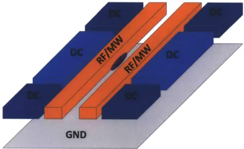
The CPW RF ion trap is a single layer structure, where all the trap and microwave
electrodes electrodes lay in one single plane as shown in Figure 2-3 (Giants trap
series). In this geometry the central DC electrode together with the two lateral RF
electrodes naturally form a coplanar waveguide structure (CPW), which can be used
Figure 2-3: RF ion trap with integrated microwave coplanar waveguide (Giants trap series).
for microwave radiation delivery (Figure 2-4). An RF ion trap built around a CPW alleviates all the problems presented by the previous two structures, with the added benefit that it can be developed in house with well established lithographic techniques. All three trap designs will be presented again in more detail in Chapter 4.
Figure 2-4: Microwave electric field distribution above a CPW transmission line.
2.2
Theory of ion trapping in RF quadrupole traps
Earnshaw's theorem forbids the trapping of the ions in a stable configuration with just static electric fields. With a combination of static and RF electric fields is possible to form a dynamically stable trap for charged particles. The theory of the RF ion
traps has been covered in depth in many publications before [Gho96, MGW05]. Here I review only the main mathematical results concerning the ion confinement in RF ion traps.
2.2.1
Mathieu equations and the adiabatic approximation
Consider a charged particle of mass m and charge
Q
interacting with a set of DC and RF electric quadrupole fields (Figure 2-5). Assuming that the particle trajectory is confined around the saddle points of the two fields, the corresponding electric poten-tials can be approximated by series expansion up to the second order in coordinates around the saddle points:Figure 2-5: RF electric field distribution in a surface electrode ion trap. The ions are trapped at the RF field null (red dot).
3 3
DC (1) ~ Uo 1
+
acXi
+b
Dcz+ , (2.1a)i=1 i,j=1
3 3
<b F , o1+ aRF RF
4PRF (Xi t)
VO 1(
+
a.
aFXi+
>
bj,
±..)+
cos(Qt),
(2.l1b)
i=1 i,j=1
where Q is the RF field angular frequency. If the saddle points of the two fields coincide (experimentally known as compensation) and taking them as the coordinates system origin, the linear terms in the series expansions become zero (Bi<D () |,=o = 0, Vij):
3
(IDC (I) ~ Uo
I +
>ib
CX+X . , (2.2a)i,j=1 3
RF(t)
VO
1±+
F
+
...
cos(Qt).
(2.2b)
ij=1
We note that, without loss of generality, the coefficients b can be taken to be sym-metric under the permutation of their indices, and thus forming two real symsym-metric traceless matrices (traceless because V2
(z)
= 0). With the above expressions for the potentials (2.2) the motion of the charged particle is described by the Lagrangian:3 3 3
L
(QUO
1
+
b
FXiX+...
cos(Qt),i=1 ij=1 i,j=1
(2.3)
from which the equations of motion are readily determined:3 3
mzj
+ 2QUOE b DCX+ 2QVO
Y,
b
RFXj cOS(Qt) = 0, i = 1, 2,3.(2.4)
j=1 j=1
The system of differential equations (2.4) can be decoupled only if the two matrices
{bPc}
and
{bF}
commute, i.e the DC and RF potentials bilinear expansions have
the same principal axes. Assuming that the commutation condition is satisfied, after the diagonalization of b matrices the equations of motion (2.4) become:
mXi
+ 2QUeb
CX, + 2QVOb FX, cos(Qt)=
0,i = 1, 2,3, (2.5) where X are the principal axes and bC,RF are the corresponding eigenvalues. By introducing the notations:8QUeb pC
4QVob
F IaT= 2
,
2 T -Qt,(2.6)
the equations of motion (2.5) take the form of the standard homogenous Mathieu's differential equations:
d
2X
dr2
+ [ai
- 2qi cos(27)]X%
=0.
(2.7)
According to Floquet's theorem (or Bloch's theorem), the solutions to the Mathieu's
equation have the form:
ui(r) = e"'f(7), U2(r) = e~4'f(-T), (2.8)
10
8
6
4
2
-10
-5
0
5
q
10
Figure 2-6: Stability map of Mathieu's equation (stable regions are shaded).
where
f
is a periodic function of period 7r and the characteristic exponent pL
=
a + i#
is a complex function of the parameters a, q. If a
#
0, or a
=0 A
#
Z the two
solutions (2.8) are linear independent, but only the case a
=
0 A#
Z provides stable
solutions as T -+ 00 (Fig. 2-6). For the case in which
a
= 0 A 3 E Z (but q / 0)the two solutions (2.8) become linear dependent and it can be shown that the second
linear independent solution is unstable as
r -+oo. If the condition
# ZZ
is satisfied
then the general solutions to the equation (2.7) can be written as:
DO00
X(TF) =Cieplr 13 cne2nir + C 2e7Itv
Z
cne -2ni-r(2.9)
n=-co n=-00G
where the constants C must be determined from initial conditions. Substitution of the solution (2.9) back into the differential equation (2.7) gives the following recurrence relation for the coefficients cn:
'Yn(A)cn- 2 + cn + 'Yn(p)cn+2 = 0, (2.10)
with
7n(P) = q (2.11)
(2n - ipt)2 - a
The characteristic exponent p is determined from the equation:
A(p) = 0, (2.12)
where A (p) is the determinant of the system of equations (2.10). Equation (2.12) can be reduced to a simpler form:
cosh(7ry) = 1 - 2A(0) sin2 (r Va). (2.13)
In the stable domain p is purely imaginary and the solution (2.9) can be written as a real Fourier series:
00 00D
X(T) = C1 cn cos[(2n +
#)r]
+ C2 cn sin[(2n + #)r]. (2.14)n=-OO n=-oC
For the case in which the variation of the applied fields is negligible over the particle motion amplitude the adiabatic approximation can be used to determine the charged particle trajectory. In this case it is assumed that the particle motion consists in a small amplitude oscillation at the frequency Q of the applied RF field superimposed over a smooth secular motion driven by the DC field. Thus, we expect that the solution has the form:
X(t) = U(t) + (Q(t), (2.15)
where (Q(t) oscillates at frequency Q, and where the average of X(t) over one period of the RF field is equal to u(t). Plugging this approximation in the equation of motion
(2.5) and expanding up to the first order in (a, we obtain:
d
2u
d
2(q
Q
[
dEDCdE
RF
d + dF r m EDC + (a + ERF coS(Qt) + d cos(t) , (2.16)
dt2 dt2 -M,
dX
Qt)where the electrical potentials where replaced by their corresponding fields. The next step of the approximation is to require the oscillating terms and smooth varying terms to separately satisfy the equation of motion (2.16). So for the oscillating term we obtain:
d2
mE(2.17)
dt2 m
with the solution:
Q
I
(oQt = - 2ERF S(t) 2.8
mQ
Substituting the above result back into the equation of motion (2.16) and averaging over the oscillating period, the equation of motion for the smooth varying part u(t) becomes:
d2u
Q
DC Q2 dERF (2.19)dt2 m m2Q2 (ERFddX COS (2t1))
from which it follows that the secular motion is determined by the an effective (pseudo) potential:
4eff(X) = 4 DC(X) + 4mQ2
FRF(X). (2.20)
of the particle confinement can be obtain without solving the exact equation equations of motion (2.14) or knowing the particle's initial conditions (Fig. 2-7). By replacing the definitions of a and q into Eq. (2.20) and solving the equation of motion in the secular approximation, we obtain the solution:
Figure 2-7: Example of a pseudopotential for a surface electrode trap obtain by numerical modeling.
(2.21)
where A and B are two integration constants. By comparing the solution (2.21) with the exact solution (2.14), we recognize that the adiabatic approximation is equivalent with expanding the exact solution up to n = ±1 terms, which is true if the imaginary part of the characteristic exponent satisfies the condition:
#2 ~ a
+
- 1.2 (2.22)
2.2.2
Boundary element method for numerical simulation
In practice any quadrupole ion trap is a set of metallic electrodes held at fixed posi-tions with respect to each other, on which either DC or RF voltages are applied. But
2)
(7 1_ 2)
u(t) = A cos
(a + q' -t + B sin a + q _tin order to analyze their trapping properties it is necessary to know the potentials created outside of the trap electrodes. Except for highly symmetric trap geometries most often it is impossible to derive an analytic solution for the trapping potentials. The recourse is to either numerically solve the trapping potentials or to experimen-tally characterize the trap, although the latter case becomes unfeasible when the search space for the applied voltages is high. Essentially, the numerical modeling of the trapping potentials reduces to solving the Laplace equation for the potentials for a given set of boundary conditions. The main numerical methods for solving partial differential equations (PDE) are boundary element method (BEM) and finite element method (FEM) [JinO2], with the former method being particulary suitable for mod-eling surface electrode ion traps (although BEM has few other advantages over FEM: only surfaces need to be discretized, the solution is more accurate since BEM solves the equivalent integral equation, there is no need for unphysical bounding boxes, etc.). The boundary element method starts with the observation that the applied electrode voltages are equivalent with a set of (surface) electric sources and related to them by the Poisson equation (only the electrostatic case is considered here; the retardation effects for the RF potentials can be safely neglected for the frequencies and distances involved in the ion traps):
v
2
(z)
=-
,(2.23)
which in integral form and specifically for the electrode surface only becomes:
1o- (:') d2 I(.4
Delectrode (5) = electrde d'. (2.24)
47rco scetr y - zX
In principle, the integral equation (2.24) can be solved analytically for the equivalent surface charge density, but in practice except for very simple trap geometries the method becomes very cumbersome (the problem is equivalent with finding a com-plete set of orthogonal functions over the surface of all electrodes). This is the point where the surface discretization comes into play. The electrode surfaces are com-monly tessellated with variable shaped triangles and/or fixed size squares. For both
tessellation shapes the integrals appearing in Eq. (2.27) have analytical solutions, which helps in speeding up the numerical computations. The choice between tiling with triangles or squares depends on the geometry of the problem. Triangles can approximate curved boundaries or surfaces very well, but their description requires nine real numbers (three for each vertex). On the other hand, squares are suitable for tiling flat rectangular surfaces (which is often the case for surface electrode ion traps), and their position and orientation can be described with only five real numbers. Let us assume that all the trap electrodes were divided in a set of finite size elements; then equation (2.24) takes the form:
1 f c (:') 2 I
(I i - GIelectrode (Xi) - al- d2x'. (2.25)
7
j all surface elements Si
There is leeway in where exactly the potentials are evaluated and in what position dependence for the charges we assume. The most common choice is to evaluate the discrete set of surface potentials at the corresponding geometric center of each surface element (i.e. collocation method) and to assume constant surface charge densities over each surface element. Under these conditions equation (2.25) can be written further as:
elem es 2X (2.26)
jC all surface elements i
or
4)Z Mijo-n, Mii =4 jp d2x. (2.27)
47eo s.7 |$ -- 1|
Since the surface voltages are given, finding the discrete set of surface charges -j is just a matter of inverting the matrix formed from the elements Mij:
lo-)
= M- 1l)),
(2.28)where we used Dirac notation. With the equivalent electric charges known, the elec-trical potentials can be easily determined anywhere in space:
(DV)
= 1
E/
1
d
2X.(2.29)
47rEo s
x-z
Since the electrical potentials satisfy the superposition principle Eqs. (2.28) and (2.29) can be solved only once for any arbitrary set of applied voltages:
aj (k)
=M "Di (k), i (k)
=1, i
- electrode with voltage V(2.30a)
0,
otherwise
47rc Ic-l Vk
5j
u(k)
XjkE all independent voltages jE all surface elements iS
(2.30b) Equation (2.28) can be solved numerically by some simple method such as Gaussian elimination, but equation (2.30a) requires applying the method for every independent applied voltage, which becomes time consuming. The alternative is to invert the matrix M before proceeding with solving the set of equations (2.30). There are various ways to numerically invert matrices, but considering the capabilities of a desktop computer and the programming language used, few aspects must be kept in mind when choosing the matrix inversion algorithm. In most cases the matrix to be inverted would not fit in the computer RAM memory in which case it is necessary to break it in sub-matrices of lower dimensionality (the alternative is to just use the programming language linear algebra pack inversion algorithm and to let the computer utilize the virtual memory, but the computation becomes exceedingly slow). One such matrix inversion algorithm which satisfies the above requirements is based on block LDU decomposition [Ste98]. Suppose that the matrix M is partitioned in sub-matrices of various dimensionalities with the only restriction that the main diagonal blocks must be square (i.e. be invertible):
'l :M1,N
M =
-.
-
..--.
Mii
Mi'i+1
..
..
(2.31)
-.. - ..
Mi+1,i Mi+
1,i+ 1MN,1 MN,N
then the following pseudocode implements the in place inversion of matrix M:
! LDU decomposition for i=1 to N-1
M[i+1:N;i]=M[i+1:N;i]*M$_i,i^-1$
M[i+1:N;i+1:N]=M[i+1:N;i+1:N]-M[i+1:N;i]*M[i;i+1:N] end for i ! M inversion for j=1 to N Mj,j=Mj, -1 for i=1 to j-1 Mj,j=-Mj, *M [i; i:j-1*M
[i:j-1; j]
end for iend for
j
for i=N-1 to 1 step -1
a=M[i+1:N;i] M[i+1:N,i]=O
M[1:N;il=M[1:N;il-M[1:N;i+1:N]*a
end for i
where the notation M[i + 1 : N; i], for example, stands for all blocks from row i + 1 to row N on ith column of matrix M. In Appendix A I present an example of this algorithm implemented in Mathematica 7.
2.3
CPW microwave resonator
The use of microwave resonators based on transmission lines was proposed before as a method to realize cavity quantum electrodynamics with superconducting electrical circuits [BHW+04], which was subsequently demonstrated experimentally [WSB+04). The same microwave resonators based on transmission lines can be also used to realize cavity quantum electrodynamics with molecular ions. Here, I give a short classical description of the CPW microwave resonators integrated in surface electrode ion traps.
2.3.1
Classical description of CPW microwave resonators
Let us consider a lossless microwave resonator formed from a CPW transmission line of length L embedded between two semi-infinite CPW transmission lines but separated from them by two small gaps. We model the transmission lines as a distributed set of capacitances c and inductances
1
(and as such both the resonator itself and the semi-infinite transmission lines have the same characteristic impedances Z), while for simplicity the coupling gaps are modeled as two capacitor of capacitance Co [Wad9l, SimOl, MYJ80]. Assuming that the system is fed from the left with a sinusoidal signal of amplitude V+ at frequency w, the left semi-infinite line will contain a positive propagating current wave and a reflected negative propagating wave, and the right semi-infinite line will contain only a positive propagating current wave, while the resonator will contain both types of current waves (see Fig. 2-8). Since the system is driven at a single frequency w in the following all the appearing quantities will implicitly contain a term of the form exp(iwt). In order to determine the resonator properties, we make use of the charge conservation law at the two coupling gaps:VL_ L gC kk _g+ikk dL IL + dQL iQL, (2.32a)
Z
Z
dt
Vj _ Vg+ - y -ik k dQR RZ
-d
-iQR, (2.32b)Z
Z
dt
where the currents were written in terms of their associated voltage amplitudes, and where the subscripts +/- show the direction of propagation of the respective waves.
Figure 2-8: CPW based microwave resonator.
The charges on two coupling capacitor QL,R are related to voltage drops across the two gaps by the relations:
VL
(V + VL _ (+6eiki +ikL) (3AVR = (V+e ik2 + V - - V= Q (2.33b)
The set of linear equations (2.32) and (2.32) can be solved for the unknown voltages as function of the applied voltage Vf. Making the notations
#
=2wCoZ
= 2k- andC
-= e--2k, the results are:
VL +±i)±+GWi) 3 L (2.34a) V = V+,(2.34b) [1 + _y(# - z)2] V+ 3/4 (1 + #2) (0 _ i) VL(23b # [1 + _y(# - z)2]
V_=
-y 1/4 (1 +#
2)i VL (2.34c) #[1+ y(# - i)2] + V - 1/2 (1 + #2) V(2.34d)
[1 + -y(# - z)2] V+If the feeding line is to be electrically matched to the resonator, there should by no reflected wave inside the feeding line. This is equivalent to setting the Eq. (2.34a) equal to zero, from which we obtain a condition for the length L of the resonator has