Penetration of Water into Uncracked and Cracked Steel Reinforced
Concrete Elements; Visualization by Means of Neutron Radiography
P. Zhang1, F. H. Wittmann1, 2, T. Zhao1 and E. Lehmann3
1Qingdao Technological University, Centre for Durability Studies, China, 2Aedificat Institute Freiburg (AIF), Germany,
3Paul Scherrer Institut (PSI), Villigen, Switzerland
Abstract
Service life of reinforced concrete structures depends on the quality of concrete, the cover thickness, and the aggressiveness of the environment. Water and harmful compounds dissolved in water are taken up into the porous structure of concrete by capillary action and diffusion or a combination thereof. The combined process is very complex and cannot be described by simple models. Therefore prediction of service life of reinforced concrete structures in aggressive environment remains unreliable. In this contribution it will be shown that neu-tron radiography is a very powerful method to study moisture uptake and movement in porous materials such as concrete. Results will provide us with a solid basis for reliable predictive models.
First fundamentals of the test method will be briefly described. It will be shown how this method can be applied to follow the time dependent process of capillary suction quantitatively. In addition uptake of water in the vicinity of cracks has been studied in some detail. It is of particular interest that movement of water into the interface between steel reinforcement and concrete and into the fracture process zone ahead of a crack tip can be visualized and determined quantitatively by means of neutron radiography. It is the first time that these decisive processes with respect to durability can be studied in detail. The obtained results will be discussed and the potential of the test method for future investigations will be outlined. Results presented in this contri-bution will help us to understand better deteriorating processes in reinforced concrete structures and to find ways to improve durability.
Eindringen von Wasser in Stahlbetonbauteile mit und ohne Risse; Visualisieren mit
Hilfe der Neutronenradiographie
Zusammenfassung
Die Nutzungsdauer eines Stahlbetontragwerkes hängt in erster Linie von der Betonqualität, der Dicke der Überdeckung und der Aggressivität der Umgebung ab. Sowohl Wasser als auch die in Wasser gelösten Schadstoffe werden durch Kapillarkraft und Diffusion beziehungsweise eine Kombination dieser beiden Mechanismen in den Porenraum des Betons aufgenommen. Der kombinierte Transportprozess ist komplex und kann deswegen nicht mit Hilfe von einfachen Modellen wirklichkeitsnah beschrieben werden. Aus die-sem Grund bleibt die Vorhersage der Nutzungsdauer von Stahlbetontragwerken in aggressiver Umgebung bis auf den heutigen Tag unzuverlässig. In diesem Beitrag wird gezeigt, dass die Neutronenradiographie eine leistungsfähige Methode ist, mit der die Aufnahme und Bewegung in porösen Werkstoffen wie etwa Beton mit hoher Genauigkeit untersucht werden kann. Die Ergebnisse liefern uns eine solide Basis für die Entwicklung zuverlässiger Modelle für die Vorhersage der Nutzungsdauer.
Zunächst werden die Grundlagen der hier vorgestellten Untersuchungsmethode kurz beschrieben. Dann wird gezeigt, wie diese Methode dazu verwendet werden kann, die kapillare Wasseraufnahme quantitativ zu verfolgen. Zusätzlich wurden noch die Wasseraufnahme durch Risse und der Transport aus Rissen in das angrenzende poröse Material ins Einzelne gehend untersucht. Es ist von ganz besonderem Interesse, dass die Wasseraufnahme der Grenzfläche zwischen Stahlbewehrung und Beton sowie das Eindringen von Wasser in die Rissprozesszone (FPZ) vor der Spitze eines wirklichen Risses mit Hilfe der Neutronenradiographie sicht-bar gemacht und quantitativ bestimmt werden können. Auf diese Weise ist es erstmals gelungen, diese für die Beständigkeit von Stahlbetontragwerken entscheidenden Prozesse visuell nachzuweisen und detailiert zu untersuchen. Die erhaltenen Ergebnisse werden am Ende dieser Veröffentlichung diskutiert und das Poten-tial für weitergehende Untersuchungen wird skizziert. Die hier vorgestellten Ergebnisse werden dazu beitra-gen, schädigende Prozesse in Stahlbetontragwerken besser zu verstehen und neue Wege zu finden, die Nut-zungsdauer zu verlängern.
1
Introduction
Moisture movement in porous building materials is a crucial process for their durability. Cement-based materials are often water saturated when the form-work is being removed. Then a long lasting drying process begins. Drying is at the origin of shrinkage and shrinkage causes frequently cracks in drying structural elements. In permanent contact with water cement-based materials may also undergo damage due to hydrolysis of hydration products. Whenever pre-dried concrete gets in contact with driving rain, capillary action of the porous structure will lead to quick absorption of considerable amounts of water. Ions such as chlorides or sulphates dissolved in the absorbed water are transported deep into the mate-rial. In this way noxious compounds can seriously damage the surface near zone and corrosion of steel reinforcement may be initiated. A porous material containing more water than a critical value may also be sensitive with respect to frost action. High corro-sion rate of steel in concrete requires a critical amount of water content. Thermal insulation of brick masonry is strongly reduced at high water con-tent. There are many more examples, which all prove that we need to understand processes of water movement and the development of moisture distri-butions in porous building materials in order to improve durability and serviceability of building materials and to ascertain required service life of buildings and structures.
There are different non-destructive methods to determine moisture content in porous materials. They can be subdivided into two groups: (1) NMR methods based on electromagnetic interaction with the water in the porous material [1, 2] and (2) radio-graphy methods, based on weakening of radiation passing through the material [3, 4]. X-rays, γ-rays and neutrons have been used already in the past to visualize regions containing different amounts of water in building materials. Neutron radiography has also been applied in the past to study moisture movement in porous building materials [5-9]. In this contribution we will present new results obtained recently by neutron radiography.
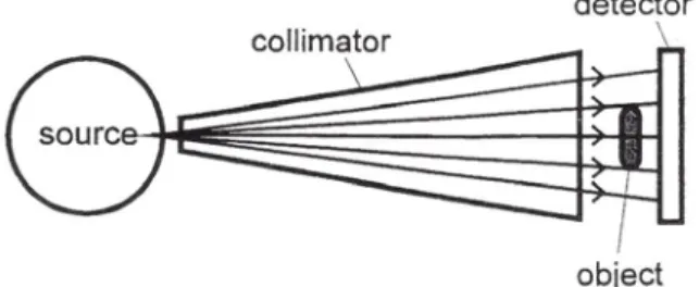
The principle of radiography is based on recording
collimator generally also contains filters to influ-ence the spectrum of the beam and to reduce beam pollution by γ-rays. Behind the object the beam is recorded by means of electronic detectors, which allow directly obtaining digital images. The regis-tered neutrons can have passed the object without interaction or they can have been scattered from another region. In order to obtain realistic moisture distributions the obtained image has to be treated by transmission analysis [7].
The neutron cross section of water is far bigger than the corresponding value for common porous build-ing materials [5]. Therefore the method is very sen-sitive with respect to determination of moisture content. On concrete plates with a thickness of 20 to 30 mm a few mg/cm3 of water can be observed with a spatial resolution of 1 mm or less [5]. This method shall be applied to observe the rate of penetration of water into pre-dried concrete. Water uptake of a region close to a crack will also be studied. The main aim of this contribution is, how-ever, to point out the unique potential of this method for following moisture movement in porous materials such as concrete or mortar. In a follow up paper the influence of surface impregna-tion of concrete with a water repellent agent will be presented and discussed.
In this contribution capillary action has been con-sidered to be the only driving force for moisture movement. This obviously is a simplification. The method shall be later applied to study moisture migration under the influence of frost suction and osmotic pressure.
Figure 1: Schematic representation of experimental set-up for neutron radiography
water as function of time can be described by means of the following equation [11]:
(1) With A being the coefficient of capillary suction [kg/m2 s1/2]; It can be shown that A has the follow-ing physical meanfollow-ing:
(2) In equation (2) Ψ stands for the water capacity of the absorbing material [m3/m3], that means the volume within the porous space, which can be filled by cap-illary suction, ρ stands for the density of the absorbed liquid [kg/m3], reff designates an effective radius [m], representing the pore size distribution of a given material, σ is the surface tension [Nm/m2]
and Θ the wetting angle of the liquid, and finally η is the temperature dependent viscosity of the liquid [(N s)/m2].
The penetration depth of the absorbed liquid as function of time x(t) can be predicted by means of the following equation:
(3) In equation (3) B is the coefficient of capillary pen-etration [m/s1/2], and has the following meaning:
(4) With equation (4) equations (2) and (3) can be linked. If the coefficient of capillary absorption A and the water capacity Ψ have been determined experimentally, the coefficient of capillary penetra-tion B can be calculated by means of equapenetra-tion (4). Obviously equations (1) to (4) have been derived and are valid strictly speaking for a single capillary or a parallel bundle of capillaries only. But within a certain range these equations can also be used as a first approximation to describe capillary absorption and penetration as function of time for real materi-als with complex porous systems such as cement-based materials.
A crack can be considered to be a slit like capillary as a first approximation. Obviously in this case tor-tuosity and surface roughness of the crack surface is neglected when the above mentioned equations are applied. The rate of penetration into a crack, however, can then be estimated by means of the fol-lowing equation:
(5) The width of visible cracks in concrete is of the order of magnitude of 0.1 to 0.5 mm, while the effective radius of cement-based materials is of the order of magnitude of some µm. We can expect that a crack will be filled nearly instantaneously as com-pared with the water penetration into the uncracked porous material.
In this simplifying theoretical approach the influ-ence of gravity on capillary rise is neglected. In wide cracks this is certainly not justified and a more rigorous approach shall be adopted in the future. It must be mentioned at this point that a macroscopic theory is not applicable to describe liquid and vapour flow in gel pores of hardened cement paste. In this case the intense interaction of water with the solid surfaces has to be taken into consideration [12, 13]. This aspect of basic research shall be con-sidered in more detail the future.
3
Preparation of Test Specimens
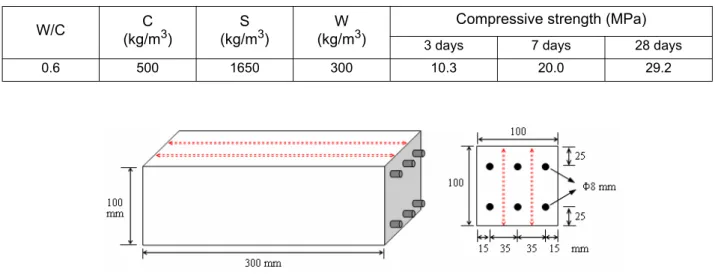
All specimens have been prepared with the same type of mortar. The composition is shown in Table 1. Ordinary Portland cement, type 42.5 (C) and local river sand with a maximum grain size of 2.5 from Qingdao area (S) have been mixed with tap water. The maximum grain size has been lim-ited to a value of 2.5 mm in order to have a repre-sentative volume in slices with a thickness of approximately 25 mm. Prismatic specimens with the following dimensions have been cast in steel forms: 100 x 100 x 300 mm3.
From the prisms slices with a thickness of approxi-mately 25 mm have been cut after 14 days of moist curing. These slices were dried in a ventilated oven at 50 °C for four days. After this drying period constant weight had been achieved. The square surfaces and two opposite small surfaces (25 x 100 mm2) were then covered with self adhesive aluminium foils. Part of the mortar prisms have been reinforced with six steel bars having a diameter of 8 mm each, as shown in Figure 2. These steel reinforced prisms were cut with a diamond saw into three slices after 14 days moist curing along the long axis of the prisms (see Fig. 2). The slices obtained in this way have been loaded by three point bending under well controlled conditions in order to induce one single crack with a given crack width in the middle (see Fig. 3). The crack width could be chosen to between 0.1 and 0.5 mm. From the inner part of the
cracked specimens slices with a width of 100 mm and the induced crack in the centre have been cut as shown in Figure 3. These slices (25 x 100 x 100 mm3) have been oven dried until constant weight was achieved and then covered with self adhesive aluminium foils as described above for the unreinforced samples.
Uncracked and cracked specimens were then ready for measuring the penetration depth of water as function of time by neutron radiography. All speci-mens were placed in contact with water in the neu-tron beam.
4
Results and Discussion
4.1 Water Penetration into the Uncracked Material
are not completely homogeneous, penetration rate is higher in the left part of the sample. This can most probably be explained by the manufacturing process of the samples and the direction of casting.
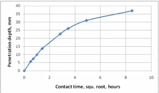
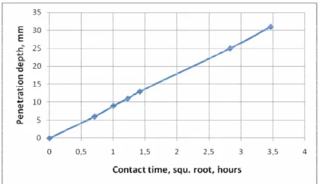
The obtained data have been further evaluated by means of earlier developed software IDL. In this way penetration profiles as shown in Figure 5 have been obtained. For the determination of the profiles the rectangular area marked in Figure 4 has been selected. The resulting profiles are shown in Figure 5. When we plot the penetration depth as function of square root of time the relation shown in Figure 6 is obtained. In this case we have chosen the inflexion point of the profiles shown in Fig. 5 as penetration depth. This corresponds to a water content of approximately 0.01 g/cm3. The relation shown in Table 1: Composition of the mortar specimens and compressive strength
W/C (kg/mC 3) (kg/mS 3) (kg/mW 3) Compressive strength (MPa)
3 days 7 days 28 days
0.6 500 1650 300 10.3 20.0 29.2
Figure 2: Position of the steel reinforcement in the mortar prisms and cutting lines
Figure 3: Formation of a centre crack under three point bending and detached specimen in contact with water for observation of capillary suction
Figure 4: Direct observation of the penetration front of water into mortar by neutron radiography up to a contact time of 72 hours
Figure 5: Moisture profiles as measured after different durations of contact between the mortar sample and water
Figure 6: Penetration depth of water along a vertical axis as function of square root of contact time
Time: 0 0:30 2:00 8:00 72:00 -0.005 0.010 0.025 0.040 0.055 0 10 20 30 40 50 Depth, mm W ater co n ten t in sam p le, g /cm 3 0:01 0:15 0:30 1:00 2:00 8:00 12:00 24:00 72:00
4.2 Water Penetration into Cracked Reinforced Concrete
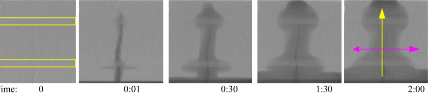
Results of neutron radiography of the plate with a crack are shown in Fig. 7. The contact time is indi-cated in hours. At time 0 that means in the dry state, the position of the steel reinforcement is indicated. When the surface of the mortar sample is put in con-tact with water, the artificial crack is filled immedi-ately with water. It was not possible to follow the kinetics of the rising water front in the crack. It is of major interest that also the damaged interface between the reinforcement and the mortar is imme-diately water filled. The interface is damaged due to the imposed bending to create the crack. Once the crack is water filled, water penetrates by capillary action horizontally into the mortar. It can be seen that the rate of horizontal capillary suction out of the crack and the vertical capillary suction from the adjacent water reservoir are approximately equal. The interface of both the lower and the upper reinforcement obviously has been damaged when the crack has been induced. Water penetrates far along the interfaces. Ahead of the real crack tip a fracture process zone has been created. Water can also penetrate easily into this pre-damaged zone. In order to get the water profiles in a quantitative way, the water content has been calculated along the two axes shown in the radiograph taken after two hours of contact with water. The vertical axis has been placed just left of the crack and the horizontal axis slightly below the centre. The results obtained are shown in Figures 8 and 9 up to a maximum suc-tion time of 24 hours.
We can see from Figure 8 that the penetration close
hours of contact with water the water capacity of the material in between the two reinforcement bars has also been reached. Above the upper reinforcement bar the material has been severely damaged by local-ized loading under three point bending. Therefore the material can absorb more water by capillary action. The increased water capacity in this region is a measure for the induced damage. The position of the steel bars is clearly reproduced by the two minima of water content in the profile. The lower interface of both steel bars embedded in concrete absorbs more water than the upper interface. This is most probably due to influence of gravity.
Water profiles along the horizontal axis shown in Figure 7 are reproduced in Figure 9. It can be seen that the crack is water filled before the first meas-urement, which corresponds to about one minute after contact of the sample’s surface with water. Then water penetrates out of the crack horizontally into the porous material. This penetration process is approximately symmetric with respect to the posi-tion of the crack.
The penetration depth along the horizontal axis is shown as function of square root of time (hours) in Figure 10. It can be seen that in this case the penetra-tion depth is very well predicted by equapenetra-tion (3) for at least 12 hours. This may be an indication that the well known skin effect of concrete [14] and the influence of gravity on vertical water penetration contribute to the deviation of results shown in Fig. 6. Precise data obtained from neutron radiography will provide us for the first time with the necessary infor-mation for the development of realistic predictive models to describe uptake of water and the noxious Figure 7: Water penetration in the vicinity of a crack as function of time (hours)
Figure 8: Moisture distribution along a vertical axis near the crack as function of time. It can be seen that the interfaces and the pre-damaged zone where the force has been applied during three point bending absorb more water.
Figure 9: Moisture distribution along a horizontal axis just below the centre. The crack is immediately filled with water. Then the water migrates under the influence of capillary force symmetrically normal to the crack surface.
Figure 10: Penetration depth of water along a horizontal axis as function of square root of contact time -0.005 0.010 0.025 0.040 0 10 20 30 40 50 60 70 80 90 Depth, mm Water co nten t i n s am p le , g /cm 3 0:01 0:05 0:30 1:00 1:30 2:00 8:00 12:00 24:00 -0.005 0.010 0.025 0.040 0 10 20 30 40 50 60 70 80 90 Position, mm Wa ter c onte nt in sa mpl e, g/c m 3 0:01 0:05 0:30 1:00 1:30 2:00 8:00 12:00
5
Conclusions
From results presented in this contribution we may conclude:
- Neutron radiography is a powerful method to observe uptake into and movement of water in porous materials such as concrete, mortar, wood, or brick masonry.
- Due to the high precision and high spatial resolution of this method, the obtained data provide us with a solid basis for the develop-ment of predictive models.
- Fine cracks are instantaneously filled with water, if the surface of concrete is placed in contact with water. In this way dissolved nox-ious chemical compounds can be transported deep into structural elements in a very short time.
- Water penetrates from a water filled crack into the adjacent material following a square root of time law.
- The water capacitance of mechanically dam-aged cement-based materials increases sub-stantially. This is one of the synergetic effects of combined mechanical and environmental loads.
- The increased water capacitance measured by neutron radiography is a measure for the mechanically induced damage.
Acknowledgements
The authors of this contribution gratefully acknowledge support of an ongoing key project by National Natural Science Foundation of China (Contract No. 50739001) and the Natural Science Foundation of Shandong Province (Contract No. Z2006F02). Substantial support by NIG-Group (Neutron Imaging and Irradiation) of Paul Scherrer Institute, Switzerland, for the neutron radiography is also gratefully acknowledged.
References
3. Lunk P. ‘Kapillares Eindringen von Wasser und Salzlösungen in Beton’ Building Materi-als Reports 8, Aedificatio Publishers Freiburg (1997)
4. Pražák J., and Lunk, P. ‘Capillary suction of AAC’ in Wittmann F. H. (ed.), Advances in
Autoclaved Aerated Concrete, Balkema,
Rotterdam, (1992) 119-123
5. Pleinert, H., Sadouki, H., and Wittmann F. H. ‘Determination of moisture distribution in porous building materials by neutron trans-mission analysis’ Materials and Structures 31 (1998) 218-224
6. Pleinert H. and Lehmann, E. ‘Quantitative neutron radiography measurment of hydroge-nous distribution‘ in Neutron Radiography (5), Proc. Fifth World Conf. on Neutron Radi-ography, Berlin (1996)
7. Pleinert, H. ‘Determination of Moisture Dis-tributions in Porous Building Materials – Neutron Signal Transfer Analysis’ Building Materials Reports 14, Aedificatio Publishers Freiburg (2001)
8. Pleinert, H., Sadouki, H., and Wittmann F. H. ‘Study of moisture transport by numerical modeling and neutron transmission analysis’ Int. J. Restoration of Buildings and Monu-ments 3 (1997) 355-370
9. Wittmann, F. H. ‘Zeitabhängige Feuchtig-keitsverteilungen in porösen Werkstoffen des Bauwesens – Numerische Simulation und Validieren numerischer Modelle mit Hilfe der Neutronenradiographie‘ Int. J. Restoration of Buildings and Monuments 10 (2004) 37-50 10. Harms A. A. and Wymann, D. R.
‘Mathe-matics and Physics of Neutron Radiography’ D. Reidel, Dordrecht (1986)
11. Zhao, T., Zhu, G., Wittmann, F. H., and Li, W.‘On Surface Impregnation of Chloride Contaminated Cement-based Materials‘ in De Clercq H. and Charola A. E. (eds.) Hydrophobe V, Proc. Fifth Int. Conf. on Water Repellent Treatment of Building Materials, Aedificatio Publishers Freiburg (2008) 311-324
Received November 5, 2008
Zhang Peng had studied Building Materials at Qingdao Technological University in
Qingdao (P. R. China) and received Master Degree in June 2006. He mainly studied the influ-ence of combined environmental loads, such as carbonation, frost action and chloride pene-tration, on durability of reinforced concrete structures in the context of his Master Thesis. He is currently pursuing his studies and works for a PhD thesis in the field of durability of rein-forced concrete structures. He worked on neutron radiography for water movement in porous building materials at Paul Scherrer Institut, Switzerland in July 2008.
E-mail: [email protected]
Prof. Dr. F. H. Wittmann, first studied physics at the universities of Karlsruhe and
Munich, Germany, and in 1969 habilitated in civil engineering at University of Technology in Munich. Since 1976 he has been holding the position of professor for building materials, first at Delft, The Netherlands, subsequently at EPF Lausanne, Switzerland, and at Swiss Federal Institute of Technology (ETH) Zurich, Switzerland. At present he is director of Aedificat Institute Freiburg and Professor at Qingdao University of Technology, Qingdao, China. His main interests and experiences are in the fields of durability of cement-based materials and application of fracture mechanics. E-mail: [email protected]
Prof. Dr. Zhao Tie-jun first studied civil engineering at North East University in Shenyang
(P. R. China) and graduated in 1984 with a bachelor degree, then shifted to Building Materials at the same University and got the master degree in 1987. He obtained his doctor degree in Building Materials from Tsinghua University in 1997. He is currently a professor in the Cen-tre for Durability, Maintenance and Repair at Qingdao Institute of Architecture and Engineer-ing and assistant vice-president of the Institute. E-mail: [email protected]
Dr. Eberhard Helmar Lehmann
1970-1974: study in physics at the University of Leipzig (Germany) – diploma as “Dipl.-Physicist”, Topic: “Molecular dynamic calculations of proteins” ; 1983: Dr. rer. nat. at the German Academy of Science, Berlin; Topic: “Cross-section data of construction mate-rials for the fast breeder reactor by reactivity measurements”.
Present Position: Group Leader “Neutron Imaging & Activation” of the Department Spalla-tion Neutron Source, Paul Scherrer Institut, Switzerland.
Field of Specialisation: Neutron Physics for Research Reactors and Spallation Sources, Applications of Neutrons in Science and Industry; Neutron Imaging, Irradiation Technology. Experience: 1976-1990: research in reactor physics for fast breeders, experimental work at different reactor stations in several countries, calculations of reactor parameters with differ-ent reactor codes; 1991-1995: reactor physicist at the research reactor SAPHIR, responsibil-ity for core design and applications; since 1995: responsibilresponsibil-ity for non-diffractive applications and spallation neutron physics of the spallation neutron source SINQ at the Paul Scherrer Institute and for neutron utilisation around the source.