Observation and Quantification of Water Penetration into Frost
Damaged Concrete by Neutron Radiography
P. Zhang (1), F. H. Wittmann (1,2), T. J. Zhao (1) and E. Lehmann(3)
(1) Centre for Durability Studies of Concrete, Qingdao Technological University, China (2) Aedificat Institute Freiburg (AIF), Germany
(3) Paul Scherrer Institut (PSI), Villigen, Switzerland
Abstract
Concrete can be damaged either by mechanical or environmental loads or by combined loads in practice. It is well known that strength and elastic modulus of concrete can be reduced significantly by frost action. But damage in the composite structure of concrete by freeze-thaw cycles will also increase uptake of water and aqueous salt solutions by capillary suction. By moisture movement service life of real concrete structures can be reduced due to ingress of dissolved nocuous compounds and by hydrolysis. Neutron radiography has been applied to investigate the influence of frost damage on water penetration into concrete. By means of this advanced method it is possible to visualize penetration of water into the porous structure of concrete and into cracks formed by frost action. Further evaluation of the test data allows determining time-dependent mois-ture profiles quantitatively with high resolution. After concrete is damaged by freeze-thaw cycles water pen-etration into ordinary concrete is accelerated. It can be shown that frost damage is not equally distributed in specimens exposed to freeze-thaw cycles. Thermal gradients lead to more serious damage near the surface. The beneficial effect of air entrainment on frost resistance has been demonstrated. After 50 freeze-thaw cycles, air entrained concrete showed no measurable increase in water absorption. But layers near the surface of concrete absorbed slightly more water after 200 freeze-thaw cycles although the dynamic elastic modulus remained constant. Results presented in this paper help us to better understand mechanisms of frost damage of concrete. The influence of thermal gradients on frost damage has been elucidated in particular.
Beobachtung und quantitative Bestimmung der Wasseraufnahme von Frost
geschädigtem Beton mit Hilfe der Neutronenradiographie
Zusammenfassung
In der Praxis kann Beton durch mechanische Einwirkung oder durch Umwelteinflüsse oder aber durch kom-binierte Einwirkungen beschädigt werden. Es ist seit langem bekannt, dass sowohl die Festigkeit als auch der Elastizitätsmodul durch Einwirkung von Frost signifikant erniedrigt werden können. Aber durch die Schädigung des zusammen gesetzten Gefüges des Betons während aufgezwungener Frost-Tau Wechsel wird auch die Aufnahme von Wasser und in Wasser gelöster Verbindungen verstärkt. Die Nutzungsdauer von Stahlbetontragwerken kann durch die Aufnahme von aggressiven Stoffen und durch Hydrolyse wesentlich verringert werden. Die Neutronenradiographie wurde eingesetzt, um den Einfluss einer Frostschädigung auf die kapillare Wasseraufnahme zu verfolgen. Mit Hilfe dieser leistungsfähigen Methode ist es möglich, den Einfluss einer Frostschädigung auf das Eindringen von Wasser in das Porengefüge des Betons in gebildete Risse zu beobachten. Die weiterführende Auswertung erlaubt es, die Feuchtigkeitsprofile als Funktion der Zeit mit hoher räumlicher Auflösung zu bestimmen. Es zeigte sich, wie zu erwarten war, dass das Eindringen von Wasser nach einer Anzahl von Frost-Tau Wechseln deutlich beschleunigt ist. Es konnte gezeigt werden, dass der Frostschaden in Proben, die Frost-Tau Wechseln ausgesetzt wurden, nicht gleich verteilt ist. Thermi-sche Gradienten während des Versuches führen zu erhöhter Schädigung in der Randzone. Die Wirksamkeit von künstlichen Luftporen zur Erhöhung der Frostbeständigkeit konnte nachgewiesen werden. Selbst nach 50 Frost-Tau Wechseln konnte keine Erhöhung der Wasserabsorption festgestellt werden. Die Oberflächen nahen Zonen zeigten aber einen leicht erhöhten Wassergehalt nach 200 Frost-Tau Wechseln. Die hier beschriebenen Ergebnisse tragen zu einem besseren Verständnis der Schadensmechanismen in Beton unter Einwirkung von Frost bei. Insbesondere der Einfluss der unvermeidbaren thermischen Gradienten konnte unter Beweis gestellt werden.
Most deterioration mechanisms in cement-based materials can be linked in one way or another with presence of water. Water is needed for expansion due to formation of ettringite and for the alkali-sil-ica-reaction for instance and water saturated con-crete is generally not frost resistant. Water penetrat-ing into the pore space of concrete can transport noc-uous dissolved chemical compounds such as sul-fates, ammonium salts or chlorides. Permanent con-tact with water or frequent wetting-drying cycles may destroy concrete by hydrolysis. Hence any reaction, which increases water exchange of con-crete with its environment, may potentially jeopard-ize durability and shorten service life. For this rea-son it is of importance to better understand forma-tion of cracks due to environmental acforma-tions and their influence on moisture movement in concrete. Cracks are always preferential paths for water flow. Cracks may be caused by mechanical load or by thermal and hygral gradients or by local swelling processes. Many authors have studied the influence of cracks on penetration of water and aggressive compounds into cement-based materials in the past [1-14]. Jacobsen et al. [13] studied the effect of freeze-thaw cycles on chloride transport into con-crete and they found that internal cracking increased the chloride penetration rate by a factor of 2.5 to 8 when compared with undamaged speci-mens. Yang et al. [14] studied water transport in concrete damaged both by tensile loading and frost cycles and reported that the presence of freeze-thaw damage increased both the initial sorptivity and total water absorption of concrete.
It is obvious that if one uses material properties measured on undamaged concrete in prediction models the performance of a structure in aggressive environment may be overestimated. There is an urgent need to modify existing prediction models in such a way that they can take into account mass transport properties modified by damage due to mechanical or environmental loads. But necessary experimental data to feed this new generation of models are scarce. By means of neutron radiogra-phy it is possible to visualize and quantify water penetration into concrete. Up to now, this technique has been successfully applied already to study water movement in different porous building mate-rials such as concrete, mortar, stone, and bricks by several researchers [15-26].
great detail in the past [27]. In most cases it is assumed that damage induced by freeze-thaw cycles is equally distributed over the tested volume. If this assumption is realistic, the overall damage can be characterized by a measured decrease of elastic modulus. During cooling of a test specimen tensile stress is created in the outer layer due to a thermal gradient. But to our knowledge a damage gradient has never been observed so far. With neutron radio-graphy, an advanced and very sensitive test method, it might be possible to demonstrate the influence of thermal gradients on internal distribution of damage. The main aim of this paper is to investigate the influence of freeze-thaw cycles on water penetra-tion into concrete by means of neutron radiography. To which extend is capillary water absorption increased by damage induced by frost action? From the raw data obtained by neutron radiography time-dependent spatial water distributions in con-crete during water penetration can be determined in a quantitative way. Frost damage usually is assumed to be equally distributed in the volume. It should be possible to observe additional damage near the surface due to hygral gradients during cooling. All results obtained will be presented and discussed. This project shall be continued to finally provide reliable data for realistic predictions of deterioration of reinforced concrete structures.
2
Experimental Procedure
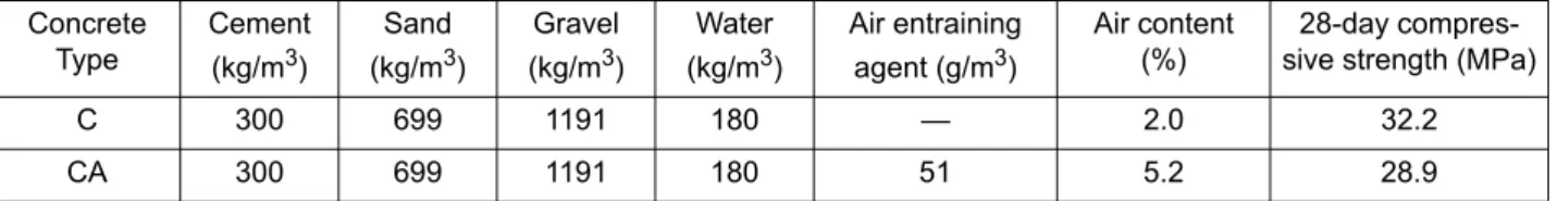
2.1 Materials and Mix Proportions Prismatic specimens with the following dimen-sions were prepared with two types of concrete, both with water cement ratio of 0.6: 100 mm × 100 mm × 400 mm. Ordinary Portland cement type 42.5, local crushed aggregates with a maximum diameter of 20 mm and density of 2620 kg/m3, river sand with a maximum grain size of 5 mm and density of 2610 kg /m3, all from Qingdao area, were used. Part of the specimens was pro-duced with the addition of 0.017 % of an air entraining agent related to the mass of cement into the fresh concrete to improve its frost resistance. The exact compositions of the two types of con-crete C and CA used in this project, and their air content and compressive strength at an age of 28 days are given in Table 1.
All concrete specimens were demoulded after one day and then stored in a moist curing room at a tem-perature of 20 ± 3 °C and relative humidity higher than 95 % until an age of 24 days. At that time all specimens were taken out of the curing room and further stored in water for another four days. At an age of 28 days, specimens were then ready for the following frost test.
2.2 Freeze-thaw Cycles
After curing concrete specimens were exposed to freeze-thaw cycles following a Chinese standard method [28]. In this case one freeze-thaw cycle lasts for about three hours. The temperature at the centre of specimens varied between -17 ± 2 °C and 5 ± 2 °C. On concrete samples without addition of air entraining agent (Concrete C), the dynamic elastic modulus has been measured after 10 and 25 freeze-thaw cycles. On concrete samples prepared with addition of air entraining agent (Concrete CA), the dynamic elastic modulus has been meas-ured after 10, 50, 100, 150, 200, 250 and 300 freeze-thaw cycles. In the following, specimens which had suffered freeze-thaw cycles are identi-fied by the appropriate concrete type followed by the number of frost cycles, as for instance, the con-crete with air entrainment exposed to 200 freeze-thaw cycles will be designated “CA-200”.
As can be expected, concrete made with air entrain-ing agent has a significantly improved frost resist-ance. Change of the related dynamic elastic modu-lus of both types of concrete, without and with air entraining agent, as function of number of frost cycles is shown in Fig. 1.
2.3 Cutting of Specimens and Water Penetration Test
After exposure of concrete C to 10 freeze-thaw cycles and concrete CA to 50 and 200 freeze-thaw cycles, selected specimens were taken out of the frost testing machine and cut in parts for water penetration tests. First a centre cube with dimen-sions with an edge length of 100 mm was cut off of the frost damaged specimens. Then two opposite layers with a thickness of 25 mm each were cut off the cube. Finally the remaining block which had the following dimensions: 100 mm × 50 mm × 100 mm has been separated into five thin slices with a thickness of approximately 20 mm. The cut-ting procedure is shown schematically in Fig. 2. Slices from the surface were designated as “-1”, the intermediate slices with “-2” and the centre slice with “-3”. The slices taken from different dis-tances from the surface allowed us to observe a presumed damage gradient.
Table 1: Composition, air content and compressive strength of two types of concrete used in this project
Concrete Type Cement (kg/m3) Sand (kg/m3) Gravel (kg/m3) Water (kg/m3) Air entraining agent (g/m3) Air content (%) 28-day compres-sive strength (MPa)
C 300 699 1191 180 — 2.0 32.2
CA 300 699 1191 180 51 5.2 28.9
Figure 1: Related dynamic elastic modulus of two types of concrete C and CA as function of the number of freeze-thaw cycles
0
50
100
150
200
250
300
0
20
40
60
80
100
Re
lated dynamic e
las
tic
modulus
/ %
Number of freeze-thaw cycles
C CA
The test samples with dimensions of 100 mm × 50 mm × 20 mm were dried in a ventilated oven at 50 °C for four days until constant weight was achieved. Then four surfaces were covered with self-adhesive aluminum foil. Two opposite surfaces with the dimensions 20 mm × 100 mm remained free for the capillary absorption test. One of the two open surfaces of the specimens prepared in this way was then placed on two line supports in a shallow aluminium container and positioned in the neutron beam. After the first image had been taken by
means of neutron radiography in the dry state of the specimens the aluminum container was filled with water as shown in Fig. 3. At this moment water started to penetrate into the frost damaged concrete. Neutron images were then taken at regular intervals following the process of water penetration into the samples. The obtained raw data were later evalu-ated by means of appropriate computer programs in order to determine time-dependent water distribu-tions quantitatively.
Figure 2: Schematic representation for cutting scheme of test specimens 100 × 100 × 400 mm
3→ 100 × 100 × 100 mm3 → 100 × 50 × 100 mm3→ 100 × 50 × 20 mm3
-1-2 -3
Figure 3: Schematic representation of experimental set-up for water penetration
100 mm
Water
5 ± 1 mm
Aluminium
film
50
m
m
2.4 Neutron Radiography
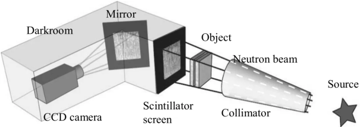
Neutron beam attenuation was widely used in industrial applications since the fiftieth of the last century. The principle of advanced neutron radio-graphy in general terms is recording of the radiation passing through an object by a position sensitive detector, a scintillator screen. The attenuation of a neutron beam can be closely related to the water content along the beam path through a given mate-rial. Hence, neutron radiography allows us to deter-mine moisture distributions quantitatively very pre-cisely and with high geometrical resolution. The basic experimental set-up of neutron radiography as used in these test series is shown in Fig. 4.
All tests were performed at the thermal neutron radiographic facility called NEUTRA of Paul Scherrer Institute (PSI) in Switzerland [19, 20]. In this case the neutron source is a spallation source called SINQ which is operated since 1997 as a steady state neutron source. In the tests, the measu-ring position was at Position 3 along the NEUTRA beam line. The diameter of neutron beam was 400 mm. The neutron flux was 3.0 × 106 cm-2s-1mA-1. The collimation ratio was 550. The mean energy of neutron beam was 25 meV. A 6Li based neutron scintillator screen was used and images were taken with a 1024 × 1024 pixel CCD camera with a low dark current (cooling tem-perature -42 °C) and a resolution of 16 bit. After the reservoir was filled with water, neutron images were serially taken every twenty seconds for up to four hours. Then the following image pre-process-ing steps were used: white spot speckle noise elim-ination, exposure normalization, flat-field correc-tion and background correccorrec-tion. In order to
visual-ize more clearly the process of water penetration into concrete, differential images from any time related to the initial time were then processed. For the quantitative evaluation of the digitized neutron radiographs, a software program called IDL was utilized. More details about quantitative calculation of water content in porous materials can be found in references [19-25].
3
Results and Discussion
3.1 Water Penetration into Concrete without Air Entrainment after Frost Damage
Neutron images of water penetration into concrete without air entrainment and without frost action are shown in Fig. 5. It can be seen immediately that by means of neutron radiography we can fol-low qualitatively the process of water penetration into porous cement-based materials. After a con-tact time of about five minutes the penetrating water front becomes visible. Then this irregular front gradually moves deeper into concrete with increasing contact time. The aggregates of the composite material are marked with the lighter areas as they do hardly absorb water. The water moves around the aggregates in the porous cement-based matrix.
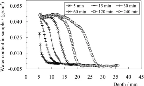
The obtained images were further evaluated by means of the software program IDL. In this way the average water distribution, the so called time-dependent moisture profile along a vertical axis in the marked rectangular area, as shown in Fig. 5, can be analyzed quantitatively. Obtained results are shown in Fig. 6.
Figure 4: Schematic representation of the test facility for neutron radiography
Source
Scintillator
screen
Collimator
Object
Neutron beam
CCD camera
Mirror
Darkroom
It has been shown earlier that water penetration into concrete follows approximately capillary theory, which means that the penetration depth as function of time can be described by means of the following simple equation [29]:
(1) Where x(t) stands for the penetration depth at time
t and B is the coefficient of water penetration. If we
assume that the depth at a given contact time when half of the maximum water content is reached
cor-responds to the average penetration depth, on the basis of results shown in Fig. 6 B is found to be 14 mm·h-1/2. This is a common value for concrete of this quality.
After exposure of the initial concrete prisms to 10 freeze-thaw cycles, concrete slices were cut off at different distances from the surface of the damaged specimens as described in section 2.3. The process of water penetration into these samples was then followed by neutron radiography. A few selected neutron images (at time of 60 and 240 minutes) are shown in Fig. 7 for the three different slices. It can Figure 5: Neutron images of water penetration into neat concrete without air entrainment before frost damage as
observed by neutron radiography after different durations of contact with water
Figure 6: Quantitative water profiles in concrete C without frost damage along a vertical axis within the rectangular area marked in Fig. 5
-0.005
0.010
0.025
0.040
0.055
0
5
10
15
20
25
30
35
40
45
Depth / mm
W
ater con
ten
t in s
am
ple
/ (g
/c
m
3
)
5 min 15 min 30 min60 min 120 min 240 min
( )
1/ 2be seen immediately that in comparison with results shown in Fig. 5 water penetrates deeper into the frost damaged concrete at the same time of contact. Quite obviously freeze-thaw damage increased the rate of water absorption into concrete. This has been observed by Yang et al. [14] before. The cor-responding water distribution profiles in different layers from the surface to centre of concrete were calculated and the resulting profiles are shown in Fig. 8. It can be clearly seen that the closer a sample was positioned to the concrete surface, the deeper water penetrates. This is a clear indication that there
exists a damage gradient. Damage decreases with increasing distance from the surface.
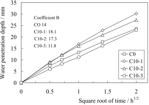
If we assume the distance where half of the total water content has been absorbed to be the average penetration depth and if we plot the penetration depth as function of the square root of contact time we obtain in agreement with Eq. (1) approximately straight lines from the data shown in Fig. 8. The straight lines as obtained from measured results shown in Figs. 6 and 8 are shown in Fig. 9. From the inclination of the straight lines we can calculate Figure 7: Water penetration into layers of concrete C, having different distances from the surface, after 10
freeze-thaw cycles after 60 and 240 minutes of contact with water as observed by neutron radiography
Figure 8: Quantitative water profiles in layers of concrete C, having different distances from the surface, after 10 freeze-thaw cycles along a vertical axis within the rectangular areas marked in Fig. 7
-0.005
0.010
0.025
0.040
0.055
0
5
10
15
20
25
30
35
40
45
Depth / mm
W
ate
r c
onte
nt in sa
mple
/ (
g/c
m
3)
C10-1, 60 min C10-1, 240 min C10-2, 60 min C10-2, 240 min C10-3, 60 min C10-3, 240 minthe coefficient of capillary penetration B (see insert in Fig. 9). It follows that the centre part of the specimen is hardly damaged while the layers closer to the surface have undergone serious damage. The coefficient of capillary penetration can be consid-ered to be a sensitive measure of damage induced into the composite structure of the material. From Fig. 7 we can also learn that frost action weakens the interfaces between aggregates and the cement-based matrix, forming preferential paths for ingress of water. This is obviously an important mechanism of frost damage which is superimposed to the classical damage in the hardened cement paste. Hardened cement paste first contracts more than the adjacent aggregates. At a critical tempera-ture hardened cement paste expands while the aggregates continue to contact. These differential deformations lead to high internal structural stresses and damage in the interfaces. This phe-nomenon has been predicted by numerical simula-tion [30]but it is the first time that the existence and the consequences of these internal structural stresses can be visualized. Both mechanisms, the complex processes of freezing of water in narrow gaps and nano-pores and the mechanical stress imposed by thermal gradients, have to be consid-ered if damage is to be predicted.
3.2 Water Penetration into Air Entrained Concrete after Freeze-thaw Cycles Direct observation of water penetration into con-crete prepared with air entraining agent by neutron radiography is shown in Fig. 10. The resulting moisture profiles are shown in Fig. 11. The water front moves into this type of concrete with slightly lower rate as compared with normal concrete (com-pare Fig. 11 with Fig. 6). This tendency has been observed before by ordinary capillary suction tests and it can be explained by the fact that the artifi-cially introduced spherical air pores break the capil-lary force locally. The artificial air pores will be filled with water very slowly and this is probably the reason why we observe two levels of water con-tent in Fig. 11, one at about 0.052 g/cm3 and the other at about 0.036 g/cm3. The pores, which remain empty for a long time even if concrete is in contact with water, assure increased frost resistance. Water in the smaller pores in hardened cement paste around the comparatively big artificial pores is under high capillary under-pressure and therefore it cannot enter the bigger spherical pores.
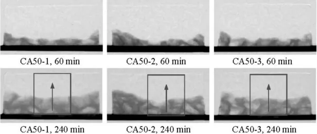
In a similar way, we followed the process of water penetration into different layers of concrete type CA after 50 and 200 freeze-thaw cycles by neutron radiography. Selected neutron images are shown in Fig. 12 and Fig. 13 for 50 and 200 freeze-thaw cycles respectively. Results at contact times of 60 and 240 minutes have been selected as examples. If we compare these results with those obtained on Figure 9: Penetration depth of water into concrete C with and without frost damage as function of square root of
con-tact time with water
0
5
10
15
20
25
30
35
0
0.5
1
1.5
2
Square root of time / h
1/2Water p
en
etration d
epth / mm
C0 C10-1 C10-2 C10-3 Coefficient B CO 14 C10-1: 18.1 C10-2: 17.3 C10-3: 11.8concrete type C without air entrainment after 10 frost cycles (see Fig. 7), it can be seen that concrete type CA absorbs after 50 and 200 freeze-thaw cycles less water than concrete type C after 10 cycles. This indicates the high efficiency of air entrainment to improve frost resistance of concrete. In addition, compared with results obtained on con-crete type CA without frost damage (see Fig. 10), there is no obvious difference observed on concrete type CA after frost action, with the exception of sample CA200-1. This means that air entraining improves frost resistance significantly but in long lasting contact with water and under a high number of freeze-thaw cycles concrete eventually will be
damaged. Under these conditions more rigorous protective measures will be needed.
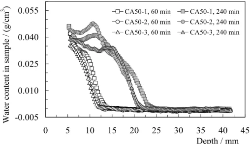
The obtained digital images on concrete type CA after 50 and 200 freeze-thaw cycles were also eval-uated by means of the computer program IDL. Detailed evaluation provides us with quantitative moisture distributions. Results along the vertical direction of the rectangular area marked in the images are shown in Figs. 14 and 15. Water profiles measured in concrete type CA from the surface to the centre after 50 freeze-thaw cycles are nearly the same as results found in specimens without frost action. Even after 200 freeze-thaw cycles, water profiles have not strongly increased except for the surface near layer.
Figure 10: Water penetration into concrete CA before frost action as observed by neutron radiography
Figure 11: Quantitative water profiles in concrete CA before frost action along a vertical axis within the rectangular
area marked in Fig. 10
-0.005
0.010
0.025
0.040
0.055
0
5
10
15
20
25
30
35
40
45
Depth / mm
W
ater content in sam
ple
/ (g/cm
3
)
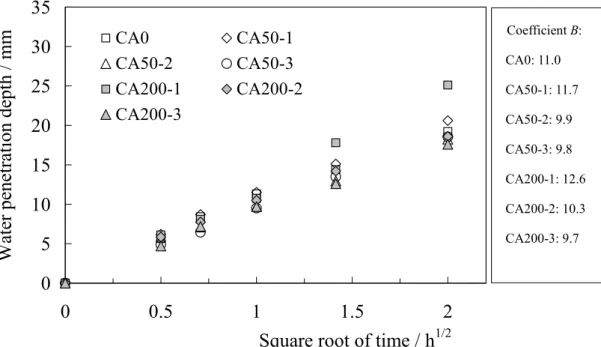
5 min 15 min 30 minAccording to the water profiles of concrete CA before and after frost action, the relationship between depth of water penetration and square root of time can be obtained in the same way as explained in Section 3.1. By means of Eq. (1) the corresponding coefficient of water penetration B can be calculated. Results are shown in Fig. 16. It can be seen that the coefficient of capillary suction of concrete type CA has not increased significantly after 50 freeze-thaw cycles, neither in the surface near layer nor in the centre layer of the concrete prism. But after 200 freeze-thaw cycles the coeffi-cient of water penetration as measured on the sur-face layer increases by 19 % compared with
undamaged concrete or centre part of concrete. As can be seen from the moisture profiles shown in Figs. 14 and 15 the artificial air pores are at least partially filled in the surface near zone. In this region the reduced capillary force is strong enough to absorb water into the spherical pores, and this process reduces frost resistance of the material.
4
Conclusions
Investigations into the water penetration into undamaged and frost damaged concrete by means of neutron radiography are described in this paper. Figure 12: Water penetration into layers of concrete CA, having different distances from the surface, after 50
freeze-thaw cycles by neutron radiography
Figure 13: Water penetration into layers of concrete CA, having different distances from the surface, after 200
Based on the results obtained, the following con-clusions can be made:
(1) Neutron radiography is a powerful test method to visualize the process of water penetration into porous materials such as concrete and to quantify the corresponding time-dependent water distributions with high precision and spatial resolution.
(2) Water penetration into ordinary concrete is increased significantly by frost damage. From the surface to the centre of the tested concrete samples, the coefficient of water penetration decreases. This value can be considered to be a measure of damage. A damage gradient can be observed.
Figure 14: Quantitative water profiles in layers of concrete CA, having different distances from the surface, after 50
freeze-thaw cycles along a vertical axis within the rectangular areas marked in Fig. 12 after 60 and 240 min-utes of contact with water
Figure 15: Quantitative water profiles in layers of concrete CA, having different distances from the surface, after 200
freeze-thaw cycles along a vertical axis within the rectangular areas marked in Fig. 13 after 60 and 240 min-utes of contact with water
-0.005
0.010
0.025
0.040
0.055
0
5
10
15
20
25
30
35
40
45
Depth / mm W ate r c on te nt in sa m ple / (g/c m3 ) CA50-1, 60 min CA50-1, 240 min
CA50-2, 60 min CA50-2, 240 min
CA50-3, 60 min CA50-3, 240 min
-0.005 0.010 0.025 0.040 0.055 0 5 10 15 20 25 30 35 40 45 Depth / mm W ate r c on te nt in sa m ple / (g /c m
3 ) CA200-1, 60 min CA200-1, 240 min
CA200-2, 60 min CA200-2, 240 min CA200-3, 60 min CA200-3, 240 min
(3) After 50 freeze-thaw cycles, water penetra-tion into air entrained concrete did not vary significantly as compared to values obtained on undamaged concrete. After 200 freeze-thaw cycles, however, the surface near zone absorbed more water although the dynamic elastic modulus as measured on the bulk material has not decreased. Damage concentrated into a thin surface near layer.
(4) In addition to the common frost damage induced by freezing of water in narrow gaps and in nano-pores, differential defor-mations between hardened cement paste and aggregates induce damage into the interfaces. This second type of damage has been simulated numerically. By means of neutron radiography it can be visualized.
Acknowledgements
The authors would like to thank Mr. Vontobel and Mr. Hartmann who work in Neutron Imaging & Acti-vation Group, Paul Scherrer Institute (PSI), Switzer-land, for the valuable help for operating neutron radi-ography. Financial support of ongoing projects by National Basic Research Program of China (“973” Project, 2009CB623203), National Natural Science Foundation of China (50739001) and Shandong Pro-vincial Natural Science Foundation (ZR2009FQ014) are also gratefully acknowledged.
References
1. K. Wang, D.C. Jansen, S.P. Shah, and A.F. Karr, Permeability study of cracked
con-crete, Cement and Concrete Research,
27(3), 381-393, (1997)
2. C-M. Aldea, S.P. Shah and A.F. Karr,
Perme-ability of cracked concrete, Materials and
Structures, 32(6), 370-376 (1999)
3. N. Hearn, Effect of shrinkage and
load-induced cracking on water permeabil-ity of concrete, ACI Materials Journal, 96(2),
234-240 (1999)
4. C.C. Lim, N. Gowripalan and V. Sirivivatna-non, Microcracking and chloride
permeabil-ity of concrete under uniaxial compression,
Cement & Concrete Composites, 22(5), 353-360 (2000)
5. P.P. Win, M. Watanabe and A. Machida,
Penetration profile of chloride ion in cracked reinforced concrete, Cement and
Concrete Research, 34 (7), 1073-1079 (2004)
6. E. Kato, Y. Kato and T. Uomoto,
Develop-ment of simulation model of chloride ion transportation in cracked concrete, Journal
of Advanced Concrete Technology, 3(1), 85-94 (2005)
7. D. Homma, H. Mihashi and T. Nishiwaki,
Self-healing capability of fibre reinforced cementitious composites, Journal of
Figure 16: Penetration depth of water into concrete CA before frost action and after 50 and 200 freeze-thaw cycles as
function of square root of contact time with water
Coefficient B: CA0: 11.0 CA50-1: 11.7 CA50-2: 9.9 CA50-3: 9.8 CA200-1: 12.6 CA200-2: 10.3 CA200-3: 9.7
0
5
10
15
20
25
30
35
0
0.5
1
1.5
2
Square root of time / h
1/2Wate
r penetration depth /
m
m
CA0 CA50-1 CA50-2 CA50-3 CA200-1 CA200-2 CA200-3Advanced Concrete Technology, 7(2), 217-228 (2009)
8. L.C. Wang, M. Soda and T. Ueda, Simulation
of chloride diffusivity for cracked concrete based RBSM and truss network model,
Jour-nal of Advanced Concrete Technology, 6(1), 143-155 (2008)
9. L. Marsavina, K. Audenaert G. De Schutter, N. Faur and D. Marsavina, Experimental and
numerical determination of the chloride pen-etration in cracked concrete, Construction
and Building Materials, 23(1), 264-274 (2009)
10. M. Kanematsu, I. Maruyama, T. Noguchi, H. Iikura and N. Tsuchiya, Quantification of
water penetration into concrete through cracks by neutron radiography, Nuclear
Instruments and Methods in Physics Research Section A, 605(1-2), 154-158 (2009)
11. V. Picandet, A. Khelidj and H. Bellegou
Crack effects on gas and water permeability of concretes, Cement and Concrete
Research, 39(6), 537-547 (2009)
12. P. Zhang, F.H. Wittmann, T.J. Zhao and E.H. Lehmann, Neutron imaging of water
pene-tration into cracked steel reinforced con-crete, Physica B: Condensed Matter, 405(7),
1866-1871 (2010)
13. S. Jacobsen, J. Marchand and L. Boisvert,
Effect of cracking and healing on chloride transport in OPC concrete, Cement and
Concrete Research, 26(6), 869-881 (1996) 14. Z.F. Yang, W.J. Weiss and J. Olek, Water transport in concrete damaged by tensile loading and freeze-thaw cycling, Journal of Materials in Civil Engineering, 18(3), 424-434 (2006)
15. R. Pugliesi and M.L.G. Andrade, Study of
cracking in concrete by neutron radiogra-phy, Applied Radiation and Isotopes, 48(3),
339-344 (1997)
16. F.C. de Beer, J.J. Le Roux and E.P. Kearsley,
Testing the durability of concrete with neu-tron radiography, Nuclear Instruments and
Methods in Physics Research Section A, 542(1-3), 226-231 (2005)
17. E.H. Lehmann, G. Kuhne, P. Vontobel and G. Frei, The NEUTRA and NCR radiography
stations at SINQ as user facilities for science and industry, In: P. Chirco and R. Rosa, Eds.
Proc. 7th World Conference of Neutron
Radiography, Rome, Italy, Aedificatio Pub-lishers, 593-602 (2002)
18. E.H. Lehmann, P. Vontobel and L. Wiezel,
Properties of the radiography facility NEU-TRA at SINQ and its potential for use as European reference facility, Nondestructive
Testing and Evaluation, 16(2-6,) 191-202, (2001)
19. H. Pleinert, Determination of Moisture
Dis-tributions in Porous Building Materials – Neutron Signal Transfer Analysis, Freiburg:
Aedificatio Publishers (1998)
20. H. Pleinert, H. Sadouki and F.H. Wittmann,
Determination of moisture distributions in porous building materials by neutron trans-mission analysis, Materials and Structures,
31(4), 218-224 (2001)
21. R. Hassanein, E.H. Lehmann and P. Vonto-bel, Methods of scattering corrections for
quantitative neutron radiography, Nuclear
Instruments and Methods in Physics Research Section A, 542(1-3), 353-360 (2005)
22. N. Kardjilov, F.C de Beer, R. Hassanein, E.H. Lehmann and P. Vontobel, Scattering
corrections in neutron radiography using point scattered functions, Nuclear
Instru-ments and Methods in Physics Research Sec-tion A, 542(1-3), 336-341 (2005)
23. R. Hassanein, H.O. Meyer, A. Carminati, M. Estermann, E.H. Lehmann and P. Vontobel,
Investigation of water imbibition in porous stone by thermal neutron radiography,
Jour-nal of Physics D: Applied Physics, 39(19), 4284-4291 (2006)
24. A. El Abd, A. Czachor and J. Milczarek,
Neutron radiography determination of water diffusivity in fired clay brick, Applied
Radi-ation and Isotopes, 67(4), 556-559 (2006) 25. P. Zhang, F.H. Wittmann, T.J. Zhao, E.
Leh-mann, P. Vontobel and S. HartLeh-mann,
Obser-vation of water penetration into water repellent and cracked cement-based materi-als by means of neutron radiography, Int. J.
Restoration of Buildings and Monuments, 15(2), 91-100 (2009)
26. V. Cnudde, M. Dierick, J. Vlassenbroeck, B. Masschaele, E. Lehmann, P. Jacobs and L.V. Hoorebeke, High-speed neutron radiography
for monitoring the water absorption by cap-illarity in porous materials, Nuclear
Instru-ments and Methods in Physics Research Section B, 266(1), 155-163 (2008)
porous solid, Journal of Colloid and
Inter-face Science, 243(1), 193-201 (2001) 28. MOHURD, Test methods of long-term
prop-erties and durability of ordinary concrete,
Beijing: Ministry of Housing and Urban-Rural Development of China (1985) 29. L. Hanžič and R. Ilić, Relationship between
liquid sorptivity and capillarity in concrete,
1385-1388 (2003)
30. T. Hoersch and F.H. Wittmann, Simulation of
damage and crack formation in the compos-ite structure of concrete under freeze-thaw cycles, In: M. Setzer, R. Auberg, and
H.-J. Keck, eds., Frost Resistance of Con-crete, Proc. Int. RILEM Workshop, Essen, RILEM, 235-241 (2003)
Zhang Peng had studied Building Materials at Qingdao Technological University in
Qingdao (P. R. China) and received Master Degree in June 2006. He mainly studied the influ-ence of combined environmental loads, such as carbonation, frost action and chloride pene-tration, on durability of reinforced concrete structures in the context of his Master Thesis. He is currently pursuing his studies and works for a PhD thesis in the field of durability of rein-forced concrete structures. He worked on neutron radiography for water movement in porous building materials at Paul Scherrer Institut, Switzerland in July 2008.
E-mail: [email protected]
Prof. Dr. F. H. Wittmann, first studied physics at the universities of Karlsruhe and
Munich, Germany, and in 1969 habilitated in civil engineering at University of Technology in Munich. Since 1976 he has been holding the position of professor for building materials, first at Delft, The Netherlands, subsequently at EPF Lausanne, Switzerland, and at Swiss Federal Institute of Technology (ETH) Zurich, Switzerland. At present he is director of Aedificat Institute Freiburg and Professor at Qingdao University of Technology, Qingdao, China. His main interests and experiences are in the fields of durability of cement-based materials and application of fracture mechanics. E-mail: [email protected]
Prof. Dr. Zhao Tie-jun first studied civil engineering at North East University in Shenyang
(P. R. China) and graduated in 1984 with a bachelor degree, then shifted to Building Materials at the same University and got the master degree in 1987. He obtained his doctor degree in Building Materials from Tsinghua University in 1997. He is currently a professor in the Cen-tre for Durability, Maintenance and Repair at Qingdao Institute of Architecture and Engineer-ing and assistant vice-president of the Institute. E-mail: [email protected]
Received May 31, 2010
Dr. Eberhard Helmar Lehmann
1970-1974: study in physics at the University of Leipzig (Germany) – diploma as “Dipl.-Physicist”, Topic: “Molecular dynamic calculations of proteins” ; 1983: Dr. rer. nat. at the German Academy of Science, Berlin; Topic: “Cross-section data of construction mate-rials for the fast breeder reactor by reactivity measurements”.
Present Position: Group Leader “Neutron Imaging & Activation” of the Department Spalla-tion Neutron Source, Paul Scherrer Institut, Switzerland.
Field of Specialisation: Neutron Physics for Research Reactors and Spallation Sources, Applications of Neutrons in Science and Industry; Neutron Imaging, Irradiation Technology. Experience: 1976-1990: research in reactor physics for fast breeders, experimental work at different reactor stations in several countries, calculations of reactor parameters with differ-ent reactor codes; 1991-1995: reactor physicist at the research reactor SAPHIR, responsibil-ity for core design and applications; since 1995: responsibilresponsibil-ity for non-diffractive applications and spallation neutron physics of the spallation neutron source SINQ at the Paul Scherrer Institute and for neutron utilisation around the source.