HAL Id: insu-02060822
https://hal-insu.archives-ouvertes.fr/insu-02060822
Submitted on 7 Mar 2019
HAL is a multi-disciplinary open access
archive for the deposit and dissemination of sci-entific research documents, whether they are pub-lished or not. The documents may come from teaching and research institutions in France or abroad, or from public or private research centers.
L’archive ouverte pluridisciplinaire HAL, est destinée au dépôt et à la diffusion de documents scientifiques de niveau recherche, publiés ou non, émanant des établissements d’enseignement et de recherche français ou étrangers, des laboratoires publics ou privés.
Hugues Raimbourg, Vincent Famin, Giulia Palazzin, Asuka Yamaguchi,
Romain Augier, Yujin Kitamura, Arito Sakaguchi
To cite this version:
Hugues Raimbourg, Vincent Famin, Giulia Palazzin, Asuka Yamaguchi, Romain Augier, et al.. Dis-tributed deformation along the subduction plate interface: The role of tectonic mélanges. Lithos, Elsevier, 2019, 334-335, pp.69-87. �10.1016/j.lithos.2019.01.033�. �insu-02060822�
Distributed deformation along the subduction plate interface: The
role of tectonic mélanges
Hugues Raimbourg, Vincent Famin, Giulia Palazzin, Asuka
Yamaguchi, Romain Augier, Yujin Kitamura, Arito Sakaguchi
PII:
S0024-4937(19)30053-2
DOI:
https://doi.org/10.1016/j.lithos.2019.01.033
Reference:
LITHOS 4963
To appear in:
LITHOS
Received date:
9 July 2018
Accepted date:
24 January 2019
Please cite this article as: H. Raimbourg, V. Famin, G. Palazzin, et al., Distributed
deformation along the subduction plate interface: The role of tectonic mélanges, LITHOS,
https://doi.org/10.1016/j.lithos.2019.01.033
This is a PDF file of an unedited manuscript that has been accepted for publication. As
a service to our customers we are providing this early version of the manuscript. The
manuscript will undergo copyediting, typesetting, and review of the resulting proof before
it is published in its final form. Please note that during the production process errors may
be discovered which could affect the content, and all legal disclaimers that apply to the
journal pertain.
ACCEPTED MANUSCRIPT
Distributed deformation along the subduction plate interface: the
role of tectonic mélanges
Hugues Raimbourga,b,c, Vincent Famind, Giulia Palazzin, Asuka Yamaguchie, Romain Augiera,b,c, Yujin
Kitamuraf, Arito Sakaguchig
(a) Université d’Orléans, ISTO, UMR 7327, 45071 Orléans, France
(b) CNRS, ISTO, UMR 7327, 45071 Orléans, France
(c) BRGM, ISTO, UMR 7327, BP 36009, 45060 Orléans, France
(d) Laboratoire Géosciences Réunion, Université de La Réunion, IPGP, Sorbonne Paris Cité, UMR 7154
CNRS, Saint-Denis, La Réunion, France
(e) Department of Ocean Floor Geoscience, Atmosphere and Ocean Research Institute, University of
Tokyo 5-1-5 Kashiwanoha, Kashiwa, Chiba 277-8564, Japan
(f) Graduate School of Science and Engineering, University of Kagoshima, 1-21-40 Korimoto
Kagoshima-city Kagoshima 890-0065, Japan
(g) Graduate School of Sciences and Technology for Innovation, Faculty of Science, University of
Yamaguchi, 1677-1 Yoshida, Yamaguchi-shi, Yamaguchi 753-8511, Japan
ACCEPTED MANUSCRIPT
1-Abstract
Recent geophysical monitoring of subduction zones has unraveled a complete spectrum of plate
coupling behaviors, from coupled portions rupturing during earthquakes to decoupled portions
slipping aseismically. However, the deformation mechanisms and the exhumed rock corresponding
to these contrasted behaviors are not yet identified. Tectonic mélange zones are thought to play a
major role in the deformation of the plate interface as they represent remnants of the subducted
plate scraped off by the overriding plate. In this work we examine several tectonic mélange zones
(Hyuga, Okitsu, Mugi) from the Shimanto Belt, an accretionary prism in southwest Japan connecting
to the active Nankai subduction zone. These tectonic mélange zones have a block-in-matrix structure,
with lenses of sandstones and basalts within a metapelitic matrix, and their deformation is
distributed over zones of hundreds of meters in thickness. In addition, the examples of mélange
considered here are bounded by sharp faults, some of them bearing pseudotachylyte layers, so that
distributed deformation within the mélange and localized deformation on its boundary are
juxtaposed. Distributed deformation involves the development of a foliation, as well as of a pervasive
network of macroscopic and microscopic shear zones. Along with slip on this network, strain
proceeds by fracturing and precipitation of quartz, in long veins parallel to the foliation or in smaller
cracks perpendicular to stretching and forming in the neck of competent lenses of sandstone s or
former quartz veins. The analysis of shear band kinematics shows in all three examples a dominant,
top-to-the-trench sense of shear, consistent with deformation along the plate boundary during
subduction. Moreover, most shear zones, when foliation is restored back to syn-subduction position,
are extensional structures. Finally, the geometry and kinematics of the mélange-bounding faults, as
well as radiometric constraints, show that in most cases the faults (=localized structures) were
formed during a later stage than mélange internal deformation. These findings bear several
consequences on the structure and dynamics of the subduction plate boundary at seismogenic
ACCEPTED MANUSCRIPT
of localized slip zones and domains of more distributed deformation. Second, rather than proposed
models of underplating, where all deformation is localized into the thrusts bounding the tectonic
sheets, we suggest that underplating was to a large extent accommodated by distributed
deformation within the mélange sheets. This underplating model accounts for (i) the large amount of
strain within the mélange, (ii) the absence of contractional structures during underplating, (iii)
thinning of the mélange required by the network of extensional shear bands and stretched boudins.
Third, mélanges appear as likely candidates for portions of the plate interface deforming by aseismic
slip. The seismic vs. aseismic character of the plate interface might depend on the ability of
sediments on top of the subducting plate to undergo distributed strain, which in turn depends on the
efficiency of pressure solution to operate.
Highlights
1) Tectonic mélanges in fossil subduction zones reveal deep deformation processes
2) Distributed strain combines pressure-solution in quartz and slip on phyllosilicates
3) Underthrusting along subduction interface results from distributed strain
4) A network of extensional shear zones formed during mélange underplating
5) Fault zones, including pseudotachylytes, formed after underplating
Keywords
Subduction zones; deformation; rheology; pressure solution; underplating
ACCEPTED MANUSCRIPT
The use of rate-and-state friction laws (Dieterich, 1994; Ruina, 1983) has proved to be a very
powerful theoretical tool to reproduce the seismic behavior that occurs along plate boundaries.
Earthquake cycles on strike-slip (Lapusta and Rice, 2003; Tse and Rice, 1986) or subduction faults
(Kato and Hirasawa, 1997; Stuart, 1988) have been successfully modelled using imposed depth
variations of friction parameters (a-b). Similarly to these models, slow-slip events (SSE), which occur
towards the shallow or deep domain of the seismogenic zone (Bilek and Lay, 2018; Dragert et al.,
2001; Obara et al., 2004; Obara and Kato, 2016; Ozawa et al., 2007; Peng and Gomberg, 2010; Saffer
and Wallace, 2015; Schwartz and Rokosky, 2007), are commonly envisioned in the mechanical
framework of friction. For example, assuming a transition from a weakening to a
velocity-strengthening behavior towards the downdip limit of the seismogenic zone results in the
spontaneous generation of SSE in this transition zone (Liu and Rice, 2005, 2007). From
mega-earthquakes to SSE, the plate interface is therefore usually modelled as a frictional interface down to
temperatures of 350-450°C where viscous processes are thermally activated (Hyndman et al., 1997;
Oleskevich et al., 1999).
Considering the plate interface as a frictional surface, the corresponding natural structures are faults,
which have been thoroughly studied and described in transcurrent settings (Chester and Logan,
1986; Faulkner et al., 2010; Faulkner et al., 2003; Sibson, 2003; Wibberley and Shimamoto, 2003) .
Common models of faults revolve around a single or a small number of high-strain fault cores or fault
gouge bands (=principal slip zones), surrounded by a damage zone. The thickness of the principal slip
zones which accommodate most of the strain, although depending on the nature of the wall rock
(Faulkner et al., 2010; Faulkner et al., 2003), is always thinner than a few meters and often restricted
to a dm- to cm-thick layer of gouge or ultracataclasite (Sibson, 2003; Wibberley and Shimamoto,
2003).
In subduction zones, seismic discontinuities interpreted as plate boundary décollements have been
ACCEPTED MANUSCRIPT
the Nankai Trough (Shipboard Scientific Party, 1991, 2001) or the Barbados (Maltman et al., 1997)
décollements consist of a 5-30m thick zone concentrating, with respect to surrounding rocks,
abundant deformation structures such as breccia and faults (Nankai Trough), or clay scaly fabrics
(Barbados and NE Japan). Observations at larger depths are beyond the reach of active margin
drilling and rely on fossil structures (e.g. (Rowe et al., 2013; Vannucchi et al., 2012a)). In the
Shimanto Belt, the Cretaceous to Mesozoic accretionary prism bordering SW Japan, the Nobeoka
Tectonic Line (NTL) is a large-scale, out-of-sequence fault that accommodated tens of km of
displacement (Raimbourg et al., 2014a). Even though a damage zone is observable in the footwall, all
the displacement is localized on a few cm thick cataclastic fault core (Kondo et al., 2005; Mukoyoshi
et al., 2009). A network of sharp faults, with principal slip zones thicknesses of less than 10mm and
displacement larger than a few kilometers, has also been recognized in the same belt on Shikoku
Island (Mukoyoshi et al., 2006). In the Kodiak accretionary prism in Alaska, near Pasagshak Point,
very-fine grained, black fault-rocks form a dm-thick horizon traceable over kilometers that was
interpreted as an ancient pseudotachylyte layer (Meneghini et al., 2010; Rowe et al., 2011; Rowe et
al., 2005). In the Shimanto Belt, similar cm-thick pseudotachylytes have been described, either
forming tectonic boundaries or crosscutting preexisting boundaries (Ikesawa et al., 2003; Mukoyoshi
et al., 2006; Ujiie et al., 2007).
In contrast to these very narrow zones of deformation, tectonic units of disrupted metasedimentary
sequences, called tectonic mélanges, coexist with the cataclastic zones described above in many
acretionary prisms such as Kodiak, the Shimanto Belt, the Franciscan Complex, the Apennines or the
Otago Schists (Connelly, 1978; Cowan, 1985; Fagereng and Sibson, 2010; Festa et al., 2012; Kimura
and Mukai, 1991; Meneghini et al., 2009; Moore and Wheeler, 1978; Wakabayashi, 2011). Tectonic
mélanges have a block-in-matrix structure resulting from pervasive deformation and contain various
deformation structures, such as cataclastic bands and shear zones, pressure-solution foliations and
mineralized veins (Fisher and Byrne, 1987, 1990; Kimura and Mukai, 1991; Kitamura and Kimura,
ACCEPTED MANUSCRIPT
al. (2013), e.g. in the Shimanto Belt (Ikesawa et al., 2005; Imai et al., 1975; Kitamura et al., 2005;
Okumura et al., 2010; Saito et al., 1996; Sakaguchi et al., 2006) or the Apennines (Vannucchi et al.,
2010), while other mélanges are thicker than 1km, e.g. in the Northern Alps (Bachmann et al., 2009)
or in Alaska (Byrne and Fisher, 1990; Fisher and Byrne, 1987).
Tectonic mélanges appear therefore as thick deformation zones, where strain is distributed over
hundreds of meters of thickness, contrasting with localized faults (Cowan, 1974). A major question
concerns the relationship between these different deformation structures. One possible view is to
interpret all deformation structures, tectonic mélanges (=damage zones) as well as fault zones and
pseudotachylyte layers (=principal strain zones), as part of a single deformation zone (Rowe et al.,
2013). Following this line of thought, Alaskan mélanges have been interpreted as shear beneath a
master décollement (Byrne and Fisher, 1990; Fisher and Byrne, 1987, 1990), and the Hyuga Tectonic
mélange on eastern Kyushu coast has been interpreted as the damage zone of the NTL, a sharp fault
constituting its roof thrust (Kondo et al., 2005).
In this work we reexamine this interpretation of tectonic mélanges as low-strain zones within a plate
boundary zone, using new structural and microstructural data acquired through several tectonic
mélanges from the Shimanto Belt in Japan. Compiling these structural and microstructural data with
other arguments such as radiometric constraints, we show that the deformation recorded within
mélanges corresponds to a new mode of underplating. We then discuss the chronological
relationship between localized and distributed deformation.
3 Geological setting
3.1 General architecture of the Shimanto Belt and studied areas
The Shimanto Belt is a partly exhumed accretionary prism forming the southern border of Japan and
extending seaward into the active Nankai Trough margin (Kimura et al., 2016) (Figure 1).
ACCEPTED MANUSCRIPT
north to south (Taira, 1981; Taira et al., 1988; Taira et al., 1980a; Taira et al., 1980b). The belt is
schematically divided into a northern Cretaceous and a southern Cenozoic subbelts, separated by a
large-scale fault known as the NTL, on Kyushu. The Shimanto Belt consists mainly of a sedimentary
accretionary wedge, predominantly composed of sandstones and mudstones in variable proportions.
Other deep seafloor typical lithologies, such as red shales, radiolarites or basalts are volumetrically
much less abundant. Most of the sediments preserve their sedimentary bedding, defining “coherent”
units, in contrast with less abundant units of broken formations or tectonic mélanges (Festa et al.,
2012). The general architecture of the wedge is an imbrication of km-scale units, separated by sharp
contacts most often not observable on the field with an overall bedding or foliation dip to the north
or northwest. The dip is commonly around 30° or less on Kyushu (especially in the Northern Belt and
in the Hyuga mélange) and much larger on Shikoku, where most units are close to the vertical
(Raimbourg et al., 2017).
From west to east of the Simanto Belt, tectonic mélanges analyzed here are the Hyuga tectonic
mélange on eastern Kyushu (Palazzin et al., 2016; Raimbourg et al., 2014a; Raimbourg et al., 2017)
(Figure 2), the Okitsu and Kure mélanges on western Shikoku (Ikesawa et al., 2003; Mukoyoshi et al.,
2006; Sakaguchi, 1999a, 2003; Sakaguchi et al., 2006; Taira et al., 1988) and the Mugi mélange on
eastern Shikoku (Ikesawa et al., 2005; Kitamura et al., 2005) (Figure 3).
Biostratigraphic ages in the matrix are Late Eocene to Early Oligocene for the Hyuga mélange (Sakai
et al., 1984), and Campanian to early Maastrichtian (for the youngest shales) for the Shikoku
mélanges (Hara et al., 2017; Taira et al., 1988). U/Pb dating of zircon grains from intercalated tuff
layers within the Mugi mélange yielded Late Cretaceous to Early Paleogene ages (Shibata et al., 2008).
All these mélanges present a highly disrupted fabric. In most of their volume, the mélanges are
strictly made of sedimentary material, with blocks of sandstone s ± tuff layers embedded in a pelitic
matrix. Locally, pods of basalts are also present, along with lenses of deep seafloor sediments such as
ACCEPTED MANUSCRIPT
from mm- to m-scales. Basalts, which show a preserved pillow-lava structure in some instances such
as Mugi, form larger m- to tens-of-meters sized lenses. In some mélanges, the recognition of
complete or partial ocean-floor stratigraphy (i.e. the succession of pillowed basalts, radiolariarian
cherts, red pelagic clays and varicolored hemipelagic shales (Taira et al., 1988)), and the occurrence
of fault zones along the basal (i.e. southern) boundaries of basalt layers (e.g. (Kitamura et al., 2005))
led to the interpretation of mélange zones as a stack of several thrust sheets, each of them soled by a
layer of basalts. For example, three thrust sheets are described in the Okitsu mélange (Sakaguchi,
2003), five thrust sheets in the Mugi mélange (Kitamura et al., 2005), while the internal subdivision of
the Hyuga mélange is still unclear but several distinct lenses of basalts are present in the tectonic pile
(Murata, 1994, 1997, 1999). In this respect, as the different blocks present in the mélange matrix
originate from in situ tectonic dismembering of the stratigraphic succession on top of the oceanic
plate, they are not strictly speaking “exotic” blocks and the mélange proper denomination should be
“chaotic formation” (Festa et al., 2012). Nevertheless, for the sake of consistency with existing
literature on Shimanto, we hereafter keep the term “tectonic mélange”.
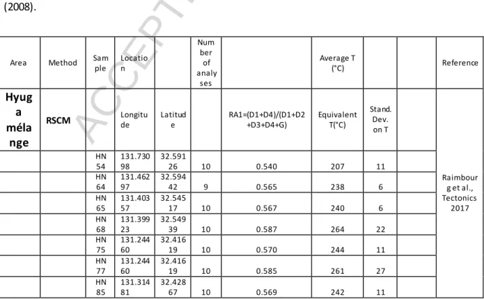
3.2 P-T conditions of deformation
Metamorphic temperatures within the Hyuga mélange inferred from vitrinite reflectance, illite
crystallinity and Raman spectra of carbonaceous matter (RSCM) geothermometers yielded similar
values of ca. 240-270°C (Hara and Kimura, 2008; Kondo et al., 2005; Mukoyoshi et al., 2009;
Raimbourg et al., 2017) (Table 1). On Shikoku, paleotemperatures in the Kure and Okitsu mélanges
are of ~225°C (Mukoyoshi et al., 2006) and 230-265°C (this study, (Sakaguchi, 1999b), respectively.
On the basis of paleotemperatures, the Mugi mélange is divided into a “hotter” upper unit at ~220°C
and a “colder” lower unit at 165-185°C (Ikesawa et al., 2005). Despite small discrepancies among
geothermometers, both vitrinite reflectance and RSCM analyses show that maximum temperatures
ACCEPTED MANUSCRIPT
Pressure estimates for the Huyga mélange, loosely constrained by the metamorphic assemblage
prehnite–pumpellyite in greenstones, are of the order of 3-5kbar (Toriumi and Teruya, 1988). In
Shikoku mélanges, some pressure estimates are primarily based on coexisting methane-rich and
water-rich fluid inclusions, and by assuming equilibrium/coeval trapping (e.g. Matsumura et al.
(2003)). This hypothesis was shown to be invalid in the Hyuga mélange (Raimbourg et al., 2014b) and
in the Okitsu mélange (Sakaguchi, 1999a), so that such pressure estimates are not reliable. Other
methods using only water-rich fluid inclusions trapped in syn-tectonic veins give an estimate of the
minimum temperature and fluid pressure that accompanied deformation (Kondo et al., 2005;
Matsumura et al., 2003; Raimbourg et al., 2015). The comparison of maximum temperature of
deformation in the rock (from vitrinite reflectance, illite crystallinity or RSCM geothermometers) and
minimum temperature in the fluid (homogenization temperature of water-rich fluid inclusions) are
close in value. As a consequence, the pressure that can be deduced from the water-rich fluid
inclusions is close to the liquid-vapor curve (where homogenization occurs) hence systematically very
low (1-2kbar), which is interpreted as the result of either (i) cycles of fluid pressure and precipitation
of the veins/fluid inclusion trapping at low points of the cycles or (ii) reequilibration of fluid inclusions
during uplift (Raimbourg et al., 2018).
3.3 Geodynamical evolution and structural settings of deformation
The first-order architecture of the Shimanto Belt, with a younging trend in stratigraphic ages towards
the south, is the main argument in favor of a model of progressive accretion and growth from
Cretaceous to Miocene. Such a model was disputed by the recognition of a collision stage in Early
Miocene, based on geological observations on-land Japan of a belt-wide unconformity (Charvet,
2013; Charvet and Fabbri, 1987; Sakai, 1988; Sakai, 1985; Sakamoto, 1977; Tanaka, 1977) and on
paleogeographic reconstructions showing the collision of SW Japan with the Northern Philippines Sea
Arc (Wu et al., 2016). The collision was responsible for the development of a vertical foliation, as a
ACCEPTED MANUSCRIPT
2017). Additionally, this work suggested that the collision stage also affected more internal domains
of the belt, through for example the movement on the NTL on Kyushu or through large-scale tilting of
the tectonic units on Shikoku.
Most studies focused on mélange units have so far considered that the ir deformation is
contemporaneous with their burial (Ikesawa et al., 2005; Ikesawa et al., 2003; Kimura and Mukai,
1991; Onishi and Kimura, 1995; Ujiie, 1997; Ujiie et al., 2007), which implicitly discards a possible
influence of the Miocene collision, much more recent than subduction processes. This issue is in fact
not so easy to solve, as the tectonic influence of the collision is attested on units from the Shimanto
Belt located south of the mélange units considered here (Raimbourg et al., 2017). In addition, ages of
deformation obtained in pseudotachylytes from faults bounding the Mugi (Tonai et al., 2016) or the
Kure (Honda et al., 2011) mélange support post-subduction activity, possibly related to the collision.
The main argument in favor of simultaneous mélange internal deformation and subduction is the fact
that this deformation is almost absent in nearby coherent units. This very strong contrast in
deformation style and intensity between mélange units and adjacent coherent units suggests that
mélange internal deformation was acquired relatively early in its history, at least before mélange
units were stacked upon adjacent coherent units. In contrast, the Miocene collisional event (Charvet,
2013) should have affected the whole tectonic pile made of mélange units sandwiched between
coherent units. On the other hand, the very localized deformation between units, in particular the
occurrence of “out-of-sequence” thrusts, such as the NTL (Kondo et al., 2005) or the fault network
cutting across Kure mélange and adjacent units (Mukoyoshi et al., 2006), could well be the
expression, at least to some extent, of posterior later collision phase. The amplitude of this collisional
phase is unclear, as there is no remaining exposed evidence of the colli ding microblock. For these
reasons, in the following section, we consider that all deformation distributed within the mélange is
coeval with subduction, while the timing of faulting, either during subduction or during later collision,
ACCEPTED MANUSCRIPT
4 Deformation within mélanges in the study area
4.1 Structures of distributed deformation
Distributed deformation is illustrated by the presence of a pervasive foliation (S1) in the pelitic matrix,
carrying flattened sandstone lenses. The foliation in Hyuga mélange strikes NE-SW and has a low dip
to the NW, e.g. N044°E 40NW in site 112 or N065°E 33NW in site 202 (Figure 4). In Okitsu mélange,
the foliation strikes WNW and is close to the vertical, e.g. N064°E 87NW in site 220 (Figure 5). In
Mugi mélange, the foliation strikes WNW and is close to the vertical, e.g. N076°E 81NW at sites
346-347-348, or N050°E 89NW at site 349 (Figure 6)
Lineation is generally difficult to observe on the foliation, except in the Hyuga mélange, which has
recorded the highest temperature conditions during deformation in its eastern area (Table 1). There,
lineation trends NW-SE, e.g. N140-N150°E on cross-section A-B, or N134°E on cross-section C-D
(Figure 4).
Macroscopic deformation is mainly represented by abundant cracks filled wi th quartz within
sandstone lenses, especially in the necked domains towards the tips of the sandstone lenses (Figure
7-A). Another conspicuous deformation feature within the mélange is a network of shear bands
(Figure 7, Figure 8 and Figure 9) deflecting the foliation within the shale matrix and the sandstone
lenses. Shear bands often occur in zones of high concentration of quartz-filled cracks (Figure 7A). The
spacing between adjacent shear bands is variable, from ~1m to a few cm (see below). Some shear
bands contains synkinematic lenses of precipitated quartz (Figure 7B and Figure 8) while in other
cases shear bands are not mineralized (Figure 7A).
4.2 Microstructures of distributed deformation
The patterns of deformation observed at outcrop-scale are transposable to smaller scales. Small
lenses composed of sandstones or siltstone, but also of precipitated quartz forming elongated
ACCEPTED MANUSCRIPT
dense array of quartz-filled fractures perpendicular both to the foliation and to the lineation, i.e.
parallel to the YZ plane (Figure 10). All the elongated and truncated lenses, including the ones
formed by precipitated quartz, are deflected by shear bands (Figure 11, Figure 12, Fi gure 13). This
deflection provides a cross-cutting criterion of anteriority of veins relative to shear bands. Quartz
lenses are most often continuous across shear bands (Figure 11 and Figure 12), even if sometimes
their thickness is much reduced by local high strain (see the necking structures in the central part of
Figure 11 and Figure 12).
At the mineral scale, the shear bands have a composite structure, incorporating a network of
chlorite-filled shear zones (Figure 13A) in addition to elongated domains of precipitated quartz
(Figure 13B). In the latter quartz domains, abundant healed microcracks, materialized by secondary
fluid inclusion planes, are oriented perpendicular to the local stretching direction (Figure 13B).
4.3. Structures of localized deformation
As mélange faults have already been largely studied (Kitamura et al., 2005; Kondo et al., 2005;
Sakaguchi, 2003; Ujiie et al., 2007, Mukoyoshi et al., 2009), this section only briefly summarize their
characteristics relevant for the present study. In contrast to distributed deformation structures,
localized fault are not scale independent: they represent large-scale structures on the outcrops,
always > 10m in length and with an overall thickness of 0.1 – 10m. In Hyuga, Mugi and Okitsu
mélanges, the largest fault zones constitute the northern boundaries of the whole mélanges. The NTL,
forming the northern boundary of the Hyuga mélange, is a major fault of the belt, associated with a
large gap in the distribution of biostratigraphic ages (Hara and Kimura, 2008) and in
paleotemperatures (ΔT° ~100°C; (Raimbourg et al., 2014a; Raimbourg et al., 2017)). In contrast, in
Okitsu and in Kure areas there is no biostratigraphic age gap between the mélange matrix and the
coherent formation north of them (Kiminami et al., 1992; Taira et al., 1988) while the
ACCEPTED MANUSCRIPT
using conversion factors from Sweeney and Burnham (1990)), and absent in Mugi (Kitamura et al.,
2005).
In some instances, fault zones also form the boundaries between individual thrust sheets within the
mélange unit (Figures 5 and 6). In particular, the Mizoochi fault zone that separates the upper and
lower sections of Mugi mélange, is associated with a temperature gap of 60°C (Kitamura et al., 2005).
Strain is very heterogeneous within fault zones, and one or several cm- to dm-thick layers of
cataclasites or ultracataclasites are present. The microstructure of the cataclasites and
ultracataclasites is much different from the mélange, as it is composed of rounded clasts of variable
sizes embedded in a very fine-grained, dark matrix. In the case of Mugi and Okitsu, evidence of
melting is found within the ultrafine-grained layers, considered therefore as pseudotachylytes
(Ikesawa et al., 2005; Ikesawa et al., 2003; Kitamura et al., 2005; Sakaguchi, 2003). A noteworthy
feature of fault zones is the quasi-absence of quartz precipitation. Localized deformation structures
rework or cut quartz veins of all kinds, and are therefore posterior to distributed deformation
structures.
4.4 Deformation kinematics
The kinematics of distributed deformation structures shares common features in all the studied
mélange units (Figure 4, Figure 5, Figure 6). First, macroscopic quartz-filled crack veins in boudins are
consistently perpendicular to the foliation plane for the three mélanges (Figure 10). In the case of the
Hyuga mélange for which a lineation is observable, quartz-filled cracks are oriented N006°E on
average, i.e. nearly perpendicular to the average direction of transport (N134°E). Second, kinematics
of shear bands and ductile-brittle structures correspond to a top-to-the-SE sense of shear, with
slickenlines oriented N134 – N150°E, in the Hyuga mélange, N145 – N157°E in the Okitsu mélange,
and N157 – N166°E in the Mugi mélange. This top-to-the-SE sense of shear is consistent with the
overall convergence direction in the whole Shimanto Belt and the asymmetry of the subduction zone.
ACCEPTED MANUSCRIPT
mélange foliation is steeply (Okitsu and Mugi) or gently (Hyuga) dipping. Finally, the slickenlines of
the major pseudotachylyte-bearing faults, observable at the boundary of the Okitsu and Mugi
mélanges, are oriented N018°E and N070°E on average in the former and latter case, respectively.
The kinematics of these faults is thus not compatible with the NW-SE direction of motion observed in
mélange shear zones.
5-Discussion
5.1 Structures and microstructures of distributed deformation in mélanges
Foliation-parallel veins are a conspicuous feature of tectonic mélanges in the Shimanto Belt as shown
on Figures 9 to 13. The orientation of healed microcracks (Figure 13B) and the
crystallographic-preferred orientation of quartz shows that these veins grew through successive events of fracturing
perpendicular to the stretching direction (Palazzin et al., 2016). Quartz-filled cracks in sandstone
lenses, perpendicular to foliation, and veins parallel to the foliation (Figure 10 to Figure 12) are
therefore kinematically consistent and were formed contemporaneously in spite of their different
orientation. Foliation-parallel veins have also been reported in the Franciscan Complex in the USA, in
the Kodiak Complex in Alaska, in the Chrystalls Beach Complex in New Zealand, and in the Internal
Ligurian Units in Italy (Fagereng and Harris, 2014; Fagereng et al., 2011; Meneghini et al., 2009;
Mittempergher et al., 2018). In these examples as well as in Shimanto, foliation-parallel veins are
interpreted as extensional shear veins and record increments of deformation in crack -seal textures
(Fagereng and Harris, 2014; Fagereng et al., 2011; Fisher and Byrne, 1990; Fisher and Brantley, 1992,
2014; Fisher et al., 1995). Conditions of formation of such veins span a large temperature range. They
can be found at low temperatures (~150°C) in the Mugi mélange lower and “colder” thrust sheets
(Kitamura et al., 2005), in the relatively shallow subduction channel of the Apennines
(Mittempergher et al., 2018; Vannucchi et al., 2010), in unlithified to semi -lithified rocks from the
Internal Ligurian Unit (Meneghini et al., 2007) and during the very shallow (40-70°C) stage of burial of
ACCEPTED MANUSCRIPT
at higher temperatures (250-300°C) in the Hyuga Tectonic mélange (Palazzin et al., 2016; Raimbourg
et al., 2015), in the Otago Schists (Fagereng and Harris, 2014) or in Kodiak (Vrolijk et al., 1988) (see
also the compilation of temperatures in (Raimbourg et al., 2018)). Additionally, at thin section scale,
a network of microscale shear bands, forming a anastomosed network parallel to the foliation,
contain a large proportion of preferentially-oriented chlorite flakes (Figure 13A), as was reported on
other mélange examples (e.g. Meneghini et al. (2009)). Bulk-rock deformation at depth, for
temperature conditions in the range ~150-300°C, is therefore the result of combined microfracturing,
solution precipitation of quartz and slip on chlorite plates.
The other conspicuous deformation feature we observed in the different mélanges of the Shimanto
Belt are macroscopic shear bands (Figure 7 to Figure 9) at a low angle to the foliation. Shear bands of
similar geometry are also present in many tectonic mélanges, such as in Kodiak (Fisher and Byrne,
1987), or in the subduction channel exposed in the Northern Alps (Bachmann et al., 2009), for T that
range from 150-400°C. There, deformation involves a combination of distributed shear zones and
extension fractures (mainly oriented parallel to the foliation), which an increasing abundance with
depth along the subduction channel.
The chronology of the deformation structures is similar between Okitsu, Mugi and Hyuga mélange
zones. The first stage of deformation involves layer-parallel extension, which results in the
development of necking of sandstone lenses, formation of tension cracks perpendicular to foliation
and foliation parallel veins (which themselves are to a large extent the result of repeated tension
microcracking, Figure 13B and Palazzin et al. (2016)). The elongated and fractured sandstones lenses
and foliation-parallel veins are then deflected by macro- (Figure 7 to Figure 9) and microshear zones
(Figure 11 to Figure 13), developed in a second stage.
A further indication on the relative timing of microstructures with respect to the mélange tectonic
evolution is provided by the comparison between Mugi, Okitsu and Hyuga, which experienced
ACCEPTED MANUSCRIPT
temperatures were the highest (ca. 240-270°C), a clear mineral lineation is visible, suggesting that
lineation developed for maximum temperature conditions. The direction of motion indicated by the
slickenlines over ductile-brittle structures carried by shear zone planes is parallel to the lineation
(Figure 4), which shows that the shear bands themselves were active for the highest T conditions, at
peak-burial conditions. Furthermore, in the Hyuga mélange, poles to tension veins (N096) and
direction of slip on shear bands (N134) are close to each other in orientation, which suggests that
veins and shear bands developed during the same framework of burial, but probably at different
depths.
5.2 Kinematics of mélange deformation
The foliation is developed in the three mélange units studied here, whereas the lineation is
well-defined only in the western domain of the Hyuga Tectonic mélange (Figure 4, see also Raimbourg et
al. (2014a)). In the rest of mélange exposures (eastern part of Hyuga, Okitsu and Mugi areas), where
temperatures did not exceed 240°C, it is therefore unclear whether the sandstone lenses within the
foliation formed by flattening, pure or simple shear.
This evolution of finite strain markers with temperature is further supported by anisotropy of
magnetic susceptibility (AMS) data. Sandstone lenses from the two sections of Mugi mélange shows
a magnetic fabrics corresponding to a flattening régime (Kitamura and Kimura, 2012), with a
well-defined foliation and magnetic lineations scattered in the magnetic foliation plane. In contrast, at
higher temperatures (~340°C, i.e. Palazzin et al. (2016)) within the Makimine mélange, the magnetic
fabrics change towards a 3-dimensional shape of a L-S tectonite (Kitamura and Kimura, 2012) and the
magnetic lineations are clustered around NNW-SSE direction, parallel to the stretching lineation
(Raimbourg et al., 2014a). The same magnetic fabrics was described in Okinawa islands, also
belonging to the Shimanto Belt, in an underplated mélange unit (Ujiie et al., 2000). In tandem with
ACCEPTED MANUSCRIPT
Belt (T~350°C) has also revealed a preferred elongation direction, parallel to the shear direction
(Kimura and Mukai, 1991; Toriumi and Teruya, 1988).
Extension parallel to the underthrusting direction is therefore revealed by the development of a clear
stretching lineation, by the AMS or by the shape fabrics of radiolarians in the higher-temperature
examples of mélanges, while in the lower temperature example the strain ellipsoid is more
ambiguous, partly because of a lack of reliable strain markers.
In addition, in the examples treated here, the clearest microstructures, in terms of kinematics, are
the macroscopic shear bands that develop within the mélanges, with directions oriented NW-SE in
Hyuga and NNE-SSW in Okitsu and Mugi mélanges. These shear bands indicate consistently
top-to-the-SE shear deformation in any example. This sense of shear is consistent with burial and
underthrusting of the mélange below Eurasia in Early Cenozoic times (Raimbourg et al., 2014a;
Sakaguchi, 1999b). Furthermore, as shear band dip is lower than the main foliation (Figure 4 to
Figure 6), when the latter is restored back to underthrusting attitude (i.e. with a low landward dip),
the shear bands become extensional structures.
Similar to these Shimanto case studies, the most commonly reported kinematic indicator in
worldwide examples of mélange reflect layer parallel coaxial extension, top-to-the-trench shearing or
both. In most cases, kinematics are interpreted as the result of shear along or near a master
décollement (Byrne and Fisher, 1990; Fisher and Byrne, 1987, 1990). In the Uyak Complex in Alaska,
conjugate normal faults are reported, with the set of normal faults synthetic with subduction-related
shear dominant over the other one (Byrne and Fisher, 1990). In the Marin Headlands of the
Franciscan Complex (Meneghini and Moore, 2007) or in the Mugi mélange of the Shimanto Belt
(Kitamura and Kimura, 2012), structures are interpreted in terms of Y-P-R brittle fabrics and the
abundant R planes are similar, geometrically and kinematically, to the extensional shear bands
described in our work. In the northern Apennines, extensional shear bands and faults are also
ACCEPTED MANUSCRIPT
channel in the Northern Alps, shear bands are widely distributed, some of them with S-C geometry,
and the preferred sense of shear is synthetic with the master shear on the décollement during
subduction (Ring et al., 1989). Therefore the general pattern is that extensional shear bands,
sometimes conjugate but in most cases synthetic with underthrusting-related shear, dominate the
deformation in mélanges.
5.3 Underplating process of mélange
Mélange units in the Shimanto Belt have a relatively constant structure, with the imbrication of
individual sheets composed of a basaltic sole below a thicker sequence of tectonic mélange
composed of sedimentary material (and minor occurrences of other ocean-floor lithologies such as
radiolarites or red and black shales). In addition, some of the basalt lenses or layers are associated
with fault zones, for example in the Mugi (Ikesawa et al., 2005; Kitamura et al., 2005) or Okitsu
mélanges (Ikesawa et al., 2003; Sakaguchi, 2003; Sakaguchi et al., 2006). The imbricated structure
and the presence of faults has led to the model of localized underplating (Figure 14B), to account for
the stacking of mélange sheets to the upper plate (Fisher and Byrne, 1990; Ikesawa et al., 2005;
Kimura and Mukai, 1991; Onishi et al., 2001; Sample and Fisher, 1986). In this model, each individual
thrust sheet is underplated at the base of the overlying plate as a result of the stepdown of the
décollement to the upper levels of the basalt of the subducting plate. The resulting structure, after
successive events of décollement step-down, is a stack of imbricated thrust sheets.
Such a model of imbrication during underplating share many similarities with fold-and-thrust belts,
which have been widely studied in the external domains of collisional orogens (Bally et al., 1966;
Chapple, 1978). Kinematics of deformation in fold-and-thrust belts has for example been derived
from passive strain markers (e.g. oolites) in the Northern Mountains, in the Appalachians, showing
that within thrust sheets the shortening axis of finite strain is close to the parallel to the transport
direction (Evans and Dunne, 1991). Microtectonic analysis, applied to fold-and-thrust belts, has
ACCEPTED MANUSCRIPT
deduced from imbrication of thrust sheets over a main thrust, as for example in Taiwan (Angelier et
al., 1986; Angelier et al., 1990; Barrier and Angelier, 1986; Chang et al., 2000) or the French Jura Belt
(Homberg et al., 2002).
Accordingly, even if most of the strain is localized on a master fault, the model of localized
underplating (Figure 14B) involves evidence for contractional deformation within the stacked thrust
sheets. Contractional deformation has indeed been described in some mélange examples. For
instance, deformation within the Kodiak mélange is divided into two stages, D1 related to shearing
during burial, D2 related to fold and thrusting and to the formation of a slaty cleavage, during
underplating and imbrication (Fisher and Byrne, 1990; Sample and Fisher, 1986; Sample and Moore,
1987). Contraction during underplating is also described in the mélange along Akamatsu river in
eastern Shikoku, Japan (Kimura and Mukai, 1991). Similarly, although the subduction channel in the
Alps is restricted to relatively shallow depths and temperatures (below ~150°C), early extensional
structures are overprinted by compressional structures (Vannucchi et al., 2008).
A major ambiguity still regards the timing of the folds and thrusts that characterize the contractional
deformation recorded in accretionary prisms such as Kodiak or the Shimanto Belt. Instead of having
formed during underplating, it may as well result from a posterior stage of deformation, within the
accretionary wedge itself. In the Shimanto Belt, a large-scale collision stage has been described,
which has largely reworked the whole structure and may correspond to most or all mesoscale
contractional structures (Charvet, 2013; Charvet and Fabbri, 1987; Raimbourg et al., 2017).
Furthermore, the first-order faults, such as the Nobeoka Tectonic Line (Kondo et al., 2005), are
out-of-sequence features, formed within the wedge after accretion. In the Alaskan case, the transition
between underplating and later-stage intra-wedge shortening is rather unclear. As a consequence, it
is difficult to assign contractional deformation unambiguously to underplating.
Furthermore, contractional deformation structures recorded in the three mélange zones investigated
ACCEPTED MANUSCRIPT
extension. In the other examples from the Shimanto Belt, distributed shortening is either limited to
the vicinity of large-scale faults (Kimura and Mukai, 1991) or not observed (Hashimoto and Kimura,
1999).
A consistent model of mélange underplating should therefore incorporate both the repetitive
formation of faults to stack thrust sheets one upon another and the dominance of extensional
deformation distributed in the volume of mélange units. Rather than a succession of two stages, a
possible model could consider that extension recorded in shear bands actually results from, and not
predates underplating (Figure 14A).
Let us assume that, as an initial stage, mélange absorbs all, or a large fraction, of the relative
displacement between the subducting and overriding plates. Such an assumption is closely related to
the “subduction channel” model, where viscous deformation is broadly distributed within a channel
of several hundreds of meters of thickness, composed of the incoming sedimentary sequence (or a
fraction of it) between two rigid walls (Cloos, 1982; Cloos and Shreve, 1988a, 1988b; England and
Holland, 1979; Mancktelow, 1995; Raimbourg et al., 2007b; Shreve and Cloos, 1986; Vannucchi et al.,
2012b). The material flowing within the channel is neither part of the lower or upper plate; its
velocity varies between null on top and plate convergence rate at the bottom of the channel (in
upper plate reference frame). This kinematic role of mélange is suggested by the abundance of
deformation microstructures (tension cracks, network of shear zones at all scales, stretching
lineation, shape of rigid lenses), even if no strain markers enables to evaluate the absolu te strain. In
addition, the subduction channel model also postulates that there is no major, actively deforming
fault bounding the sediment-filled channel. This point, discussed in the following section, is
supported by the fact that the faults that limit the mélange in its present geometry were not active
contemporaneously.
It is likely that at some point, shear will become more easily accommodated within a localized fault
ACCEPTED MANUSCRIPT
metamorphic-hardening. This scenario is required to form the internal architecture of mélange units,
with a stack of several basalt-soled sheets (Figure 5 and Figure 6). After formation of such a fault
within the oceanic crust, further subduction of the deforming mélange, connected to a more
localized slip zone within the basalts, results in thinning the subducting sediment pile. This is readily
apparent when comparing the velocity profiles across several sections at different depths. In the
model, conservation of material is imperative. Therefore, if the channel walls are fixed, the flux
through any section of the channel must be equal. Conversely, if the fluxes vary along the channel
length, then motion of the walls are required. Conservation of the material implies therefore that
when the deforming zone is thinner than incoming thickness, the roof boundary of the “channel” is
necessarily pushed upwards, to accommodate a larger influx of material than what is flowing in
(Figure 14A’4). As a result, the “nose” of the channel gets longer (at a velocity equal to burial) and its
opening angle gets smaller with time (Figure 14A2 to A’4). The material flowing through it
accommodates this thinning by the formation of synthetic extensional shear zones. Eventually, as the
shear strain rate increases towards the tip of the channel (because the material is flowing in a
thinner channel), at some point a new fault forms within the underlying basalts, and a new thrust
sheet starts forming.
Unlike models of “localized” underplating, where material is strong and deformation is localized on
faults, such a model of “distributed” underplating considers the mélange as soft and deformable,
thus accommodating most of underplating-related strain. One of the advantages of this model is to
account for the lack of shortening deformation within mélange units and the concomitance of
extension and underplating, in contrast to the examples of fold-and-thrust belts cited above. This
model also enables the connection between mélange deformation (distributed within the whole
subducting pile) and fault formation during underplating, while localized models of underplating
consider that slip occurs principally on the décollement (Fisher and Byrne, 1990; Ikesawa et al., 2005;
Kimura and Mukai, 1991; Onishi et al., 2001; Sample and Fisher, 1986), which is equivalent to
ACCEPTED MANUSCRIPT
our model also accounts for the thinning of the sedimentary pile (geometrically necessary because of
the distributed extensional shear bands), which is not incorporated in other underplating models.
5.4 Model of subduction plate boundary
5.4.1 Relationship between localized and distributed deformation
Evidence of adjacent brittle deformation features, including pseudotachylyes (Ikesawa et al., 2003;
Kitamura et al., 2005; Meneghini et al., 2010; Rowe et al., 2011; Rowe et al., 2005; Rowe et al., 2013)
and distributed deformation in mélanges has led to a model of plate interface incorporating
simultaneously zones of highly localized slip and domains of more distributed slip (Rowe et al., 2013).
This generic fault zone, forming the plate boundary, follows the fault zone model by (Faulkner et al.,
2010; Faulkner et al., 2003) composed of a ~100m-1km-wide “damage” zone, ~1-5m-wide fault-core
and ~mm-to-cm-thick slip zones.
The coexistence, of distributed deformation and localized slip features, such as pseudotachylytes, in
Kure (Mukoyoshi et al., 2006), Okitsu (Sakaguchi, 2003; Sakaguchi et al., 2006), Mugi (Ikesawa et al.,
2005) or Hyuga (Kondo et al., 2005) mélange areas within the Shimanto Belt, might suggest that they
were active at the same time, but our closer examination rather showed that they appear
disconnected for different aspects.
Disconnection is in some cases geometrical, i.e. fault zones and pseudotachylytes are late-stage, or
“out-of-sequence” faults, cutting across tectonic contacts and distributed deformation formed during
underthrusting. For example, the faults zones (including pseudotachylyte -bearing faults) present in
the Kure mélange (Mukoyoshi et al., 2006) cut across the boundary between the mélange and the
adjacent tectonic unit, so these faults were formed after the deformation within the mélange
acquired during underthrusting. This two-staged evolution is confirmed by age constraints: although
underthrusting age is imprecise, the Kure mélange is associated with the Cretaceous Belt (Taira et al.,
ACCEPTED MANUSCRIPT
(Honda et al., 2011), which were interpreted as reflecting a post-subduction stage of collision in Early
Miocene (Raimbourg et al., 2017). Similarly, the pseudotachylyte-bearing ultracataclasite forming the
roof thrust of the Mugi mélange was dated by K-Ar radiochronology at ~23-29Ma, while authigenic
illite formed synchronously with burial and deformation within the mélange yielded ages between 85
and 48Ma (Tonai et al., 2016). In Okitsu, the maximum paleotemperature, revealed by the vitrinite
reflectance geothermometer, is higher in the mélange by ~30-50°C than in the overlying unit
(Sakaguchi, 1999b; Sakaguchi et al., 2006). As discussed in (Ujiie et al., 2007), the boundary thrust,
including the pseudotachylyte-bearing fault, is therefore interpreted as an out-of-sequence thrust,
cutting across the thermal structure inherited from subduction/underthrusting stage. Similarly, the
large-scale tectonic structure of the Cenozoic Shimanto Belt on Kyushu shows that the large-scale
fault NTL is a late-stage feature cutting across a number of tectonic units and their internal
deformation, including the Hyuga Tectonic mélange (HTM) (Murata, 1996, 1997, 1998; Raimbourg et
al., 2014a). The NTL constitutes the roof thrust of the HTM on the eastern coast, but further west the
NTL cuts across the basal boundary of the HTM, so that the footwall of the NTL is there composed of
the coherent turbiditic formation underlying the HTM (Figure 2). Therefore, while on the eastern
coast the mélange deformation was interpreted as damage resulting from slip on the NTL (Kondo et
al., 2005), the map-scale relationships between the tectonic mélange and the NTL show that in
general mélange deformation predates the fault slip event on the NTL.
In these examples, the mélange deformation within the thrust sheets, interpreted as related to
underthrusting, predates more localized deformation on faults, associated in most cases with a
distinct, later-stage event. In the classical model of mélange underplating (Fisher and Byrne, 1990;
Ikesawa et al., 2005; Kimura and Mukai, 1991; Onishi et al., 2001; Sample and Fisher, 1986) (Figure
14B), there is also a clear disconnection between the mélange-forming deformation, during burial,
and slip on thrust sheets-bounding faults, during underplating. In the alternative model we propose
in Figure 14A, distributed deformation in the mélange during underplating, and repeated events of
ACCEPTED MANUSCRIPT
irrespective of the model of underplating, there is no configuration such as proposed in Rowe et al.
(2013) where large-scale faults and distributed slip act in parallel. Furthermore, as for the different
examples from the Shimanto Belt, in most instances the most localized features, pseudotachylytes,
are a later-stage event occurring within the wedge, after the underplating of the mélange at depth.
5.4.2 Seismic vs. aseismic slip along the interface – rheological models
A cm- or dm-thick fault zone deforming discontinuously through repeated earthquakes, or a
~hundreds of meters-thick subduction channel deforming through distributed shear, constitute two
theoretical end-members of the plate interface (Fagereng and Sibson, 2010). Tectonic mélanges, in
as much as they correspond to fossil plate interfaces, are thick deforming zone s akin to the second
endmember, and their role in aseismic slip, occurring in non-coupled portions of the plate
interface(e.g. (Loveless and Meade, 2010; Moreno et al., 2010)), has long been hypothetized
(Fagereng and Sibson, 2010).
Nonetheless, the actual rheology of tectonic mélanges is complex, as a result of their heterogeneous
composition, and the distribution of strain and strain rate may depend on the proportion of the rigid
blocks within the more deformable matrix (Fagereng and Sibson, 2010). Furthermore, the stability of
mélange deformation, hence their potential to host large earthquake, might also depend on the
strain rate applied, as suggested by friction tests on clay+quartz mixtures (den Hartog et al., 2012;
Den Hartog and Spiers, 2014): subduction channels deforming by velocity-strengthening processes
way switch to velocity-weakening behavior and instable slip upon an increase in strain rate (Fagereng
and Den Hartog, 2017).
To account for mélange rheology, microphysical models developed from deformation experiments of
a mixture of quartz grains embedded in a phyllosilicate matrix, are particularly appropriate (den
Hartog et al., 2013; Den Hartog and Spiers, 2014; Niemeijer, 2018; Niemeijer and Spiers, 2007;
Niemeijer et al., 2008). Bulk strain results from the contribution of quartz grain deforming by
ACCEPTED MANUSCRIPT
friction laws with parameters a and b (Dieterich, 1994; Ruina, 1983), geometrical parameters such as
shear zone thickness can be explicitly considered in microphysical models and their effect on slip
stability considered (e.g. (Fagereng and Den Hartog, 2017)). The few observations developed here on
tectonic mélange structures and microstructures of deformation provide direct constraints on such
microphysical models, hence on the rheology of the shear zones constituting the plate interface.
A key aspect of the microphysical models, necessary to trigger velocity-weakening behavior, is the
competition between slip-induced dilatational strain and compaction resulting from thermally
activated deformation of the rigid clasts. Stress corrosion cracking, i.e. sub-critical crack growth in
quartz, is invoked as a major process in the deformation of the rigid quartz clasts (den Hartog et al.,
2012; Den Hartog and Spiers, 2013), on the basis of observations in sandstone compaction
experiments (Schutjens, 1991). Nonetheless, because of the lack of quantitative constraints,
microcracking is not incorporated in the physical formulation of the clast deformation, which is
described solely in terms of pressure solution.
The structures and microstructures shown in this work point indeed to the major role played by
fracturing in the deformation of the rigid bodies at all scales. As shown by the example of the Mugi
mélange (Figure 10B and Hashimoto et al. (2006)), tension veins in boudin necks start forming at
shallow conditions, for T as low as ~150°C, marking the transition from soft sediment behavior to the
brittle behavior of cemented, low-porosity rocks (Fagereng et al., 2018). Pervasive fracturing of
competent bodies, from meter-scale lenses of sand- or siltstones to millimeter-scale veins of quartz,
can be found over the whole seismogenic depth range down to the transition to plastic deformation
(Figure 10 and (Palazzin et al., 2018)). Multiple events of microfracturing of quartz veins, attested by
crack-seal microstructures (Fisher and Byrne, 1990; Fisher and Brantley, 1992, 2014; Ujiie et al.,
2018) or quartz textures revealed by cathodoluminescence (Raimbourg et al., 2018; Raimbourg et al.,
2015) also suggest that fracturing is active throughout burial. The size and spacing of the rigid objects
ACCEPTED MANUSCRIPT
the absence of the physical laws for cracking itself. Assuming that silica, the vein-forming material, is
dissolved and precipitated locally, then the spacing between fractured quartz veins or silt-/sandstone
clasts gives an estimate of the transport distance, a key parameter of the pressure-solution flow laws
(Gratier et al., 2009). In the most strongly deformed areas, pervasive veining (Figure 11 and Figure
12) form foliation-parallel lenses of quartz with a spacing of the order or below 1mm (Palazzin et al.,
2016). Bulk-rheology, relevant at the plate tectonics scale, should account for imbricated scales,
including the deformation of rigid grains in a phyllosilicate matrix explicitly considered in the
microphysical models (Den Hartog and Spiers, 2014; Niemeijer and Spiers, 2007; Niemeijer et al.,
2008), but also larger scales, in particular the behavior of rigid lenses (in particular of precipitated
veins) in a quartz+phyllosilicate matrix.
Additionally, the large density of mode I cracks accompanying deformation of all rigid bodies (Figures
7 to 13) is a clear evidence of high fluid pore pressure attending de formation (Byrne and Fisher,
1990), even if the determination of in-situ fluid pressure from fluid inclusion record has remained so
far elusive (see the review in (Raimbourg et al., 2018)). This bears some influence on the
clasts+phyllosilicate microphysical model, as dilatancy, by decreasing the pore fluid pressure and
decreasing the effective stress, has a strengthening effect on slip (Segall and Rice, 1995). Variations in
fluid pressure have for example been described in Kodiak mélange (Vrojlik, 1987) or in the Shimanto
Belt (Raimbourg et al., 2014b), showing that the retroaction between fluid pressure and slip should
be explicitly considered.
The last insight provided by the natural examples shown in here regards the nature of the
phyllosilicate forming the network of shear zones, which is principally chlorite throughout the
temperature range (Figure 13A). A similar development of a network of chlorite is al so reported in
Kodiak (Fisher and Byrne, 1987) and in the Franciscan Complex (Meneghini et al., 2009). In contrast,
most friction experiments used to infer plate boundary rheology are based on mixtures of sm ectite,
ACCEPTED MANUSCRIPT
Friction experiments on chlorite show no large difference between illite and chlorite in terms of
friction coefficient (Ikari et al., 2009; Moore and Lockner, 2004). Nevertheless, permeability differ
significantly, and chlorite gouge have two to three orders of magnitude higher permeability than illite
gouges (Ikari et al., 2009), which potentially plays a role when considering dilatation and pore
pressure changes during slip. Furthermore, systematic data about dependence of friction on
temperature, available for quartz+illite/muscovite mixtures (den Hartog et al., 2012, 2013; Den
Hartog and Spiers, 2013) or smectite-rich natural sediments (Sawai et al., 2017), are still lacking for
chlorite.
6-Conclusions
The comparative study of several tectonic mélange units within the Shimanto Belt revealed common
features, providing insights into the processes occurring along the subduction plate boundary at
depth. Several conclusions can be drawn from mélange micro- and macrostructures of deformation,
regarding the processes of underplating and the distributed vs. localized character of deformation:
1) Distributed deformation, at the origin of the development of block-in-matrix structure of the
mélanges, results from slip on a pervasive network of shear bands, ranging from meter-scale,
quartz-filled structures to microscopic, chlorite-quartz-filled ones. Deformation on shear bands is accompanied by
pervasive veining, either in cracks formed perpendicular to extension in more competent sandstone
or quartz lenses, or in extension veins parallel to the foliation.
2) Kinematics of deformation, as deduced from the slip on shear bands, is a consistent
top-to-the-trench shear. As shear bands have in average a lower dip than the foliation, they are interpreted as
extensional structures.
3) Underplating is required by the repetition of several mélange thrust sheet units. Nonetheless, the
absence of contractional structures within the mélange leads to a new model, where distributed
ACCEPTED MANUSCRIPT
constrasting with “localized” underplating models, is in accordance with the strong partitioning of
strain within the mélange material.
4) Localized deformation on faults, including pseudotachylytes, occurs in many instances after
underplating, as intra-wedge deformation, while mélange internal deformation occurs before (i.e.
underthrusting) and during underplating. There is no evidence for a preserved structure of the plate
boundary comprising a roof thrust and underlying mélange deforming simultaneously.
5) Mélange distributed deformation is a candidate for the aseismic slip observed along certain
portions of active subduction plate interfaces. Mélange deformation features that should be
incorporated into models of the plate rheology (such as microphysical models by Den Hartog and
Spiers (2014)) include (i) the role of fracturing for clasts/rigid bodies deformation, (ii) the variable size
(hence deformation processes) of the rigid bodies embedded in a weaker matrix, (iii) the large fluid
pressure accompanying deformation and (iv) the role of chlorite to form the micro-scale network of
shear zones within the weak matrix.
Acknowledgements
This work has received funding from (i) the European Research Council (ERC) under the seventh
Framework Programme of the European Union (ERC Advanced Grant, grant agreement No 290864,
RHEOLITH), (ii) the Labex VOLTAIRE (ANR-10-LABX-100-01) and (iii) the program “Sakura” by the
French Ministry of Foreign Affairs. We thank the Editor and the two anonymous reviewers for their
ACCEPTED MANUSCRIPT
Figure and Table captions
Figure 1: Tectonic setting of the Shimanto Belt, along the southern border of Japan (Kimura et al.,
2016). The studied mélange units are located on Kyushu (see Figure 2) and Shikoku islands (see
Figure 3).
Figure 2: Geological map of Shimanto Belt on eastern Kyushu. The Hyuga mélange unit is located
below the Nobeoka Tectonic Line (NTL) over most of the area, except for the northeastern area,
where the NTL cuts across the limit between “Coherent Hyuga” and “Hyuga Tectonic mélange”
(enlarged rectangle at upper right). The Hyuga mélange incorporates, in addition to strongly sheared
sedimentary rocks, sheets of basalt and to a lesser extent of red shales. Adapted from Murata (1997).
Cross-sections A-B and C-D in Figure 4.
Figure 3: Distribution of mélange units within the Shimanto Belt on Shikoku, adapted from Taira et al.
(1988).
Figure 4: Kinematics of deformation within the Hyuga mélange (light blue color in the map and
stereoplots). Stereo diagrams are equal area, lower hemisphere, with the numbering underneath
referring to outcrops. Foliation is shown as the red plane, while planes with arrows correspond to
shear bands. Cross-section locations refer to Figure 2.
Figure 5: Structures and kinematics of deformation in the Okitsu mélange unit.(A) Map of Okitsu area,
with stereoplots of deformation kinematics. In blue stereoplots, compiling data from mélange
structures, foliation is shown as the red plane, while planes with arrows correspond to shear bands.
The pseudotachylyte-bearing fault zone along its northern boundary is associated with a
top-to-the-SSW thrust motion. Abundant shear zones in the mélange indicate top to the SE thrusting. Kinematic
data on fault zone from Sakaguchi (2003). The average azimuth of slicken lines is shown as the thick
black ticks. Stereo diagrams are equal area, lower hemisphere. (B) Cross-section of the stack of units
![[PDF] cours d Introduction au langage C# | Formation informatique](data:image/gif;base64,R0lGODlhAQABAIAAAP///wAAACH5BAEAAAAALAAAAAABAAEAAAICRAEAOw==)