HAL Id: hal-01196457
https://hal.archives-ouvertes.fr/hal-01196457
Submitted on 24 Sep 2020HAL is a multi-disciplinary open access
archive for the deposit and dissemination of sci-entific research documents, whether they are pub-lished or not. The documents may come from teaching and research institutions in France or abroad, or from public or private research centers.
L’archive ouverte pluridisciplinaire HAL, est destinée au dépôt et à la diffusion de documents scientifiques de niveau recherche, publiés ou non, émanant des établissements d’enseignement et de recherche français ou étrangers, des laboratoires publics ou privés.
NenUFAR: Instrument description and science case
Philippe Zarka, Michel Tagger, L. Denis, J.N. Girard, A. Konovalenko, M.
Atemkeng, M. Arnaud, S. Azarian, M. Barsuglia, A. Bonafede, et al.
To cite this version:
Philippe Zarka, Michel Tagger, L. Denis, J.N. Girard, A. Konovalenko, et al.. NenUFAR: Instrument description and science case. 2015 International Conference on Antenna Theory and Techniques (ICATT), Apr 2015, Kharkiv, Ukraine. �10.1109/ICATT.2015.7136773�. �hal-01196457�
NENUFAR: INSTRUMENT DESCRIPTION AND
SCIENCE CASE
1
P. Zarka,
2M. Tagger,
3L. Denis,
4J. N. Girard,
5A. Konovalenko,
6M. Atemkeng,
7M. Arnaud,
8S. Azarian,
9M. Barsuglia,
10A. Bonafede,
11F. Boone,
12A. Bosma,
13R. Boyer,
14M. Branchesi,
1C. Briand,
1B. Cecconi,
2S. Célestin,
15D. Charrier,
9E. Chassande-Mottin,
3A. Coffre,
2I. Cognard,
16,17F. Combes,
4,18S. Corbel,
19C. Courte,
20
A. Dabbech,
1S. Daiboo,
15R. Dallier,
3C. Dumez-Viou,
21M. N. El Korso,
22E. Falgarone,
5I. Falkovych ,
20A. Ferrari,
20C. Ferrari,
11K. Ferrière,
20C. Fevotte,
22
A. Fialkov,
23M. Fullekrug,
24E. Gérard, J.-M.
2Grießmeier,
25B. Guiderdoni,
2L. Guillemot,
26J. Hessels,
27L. Koopmans,
26V. Kondratiev,
1L. Lamy,
20T. Lanz,
28P. Larzabal,
29M. Lehnert,
22F. Levrier,
4,18A. Loh,
20G. Macario,
30J.-J. Maintoux,
15
L. Martin,
20D. Mary,
1S. Masson,
31M.-A. Miville-Deschenes,
32D. Oberoi,
33M. Panchenko,
25M. Pandey-Pommier,
9A. Petiteau,
2J.-L. Pinçon,
15B. Revenu,
30
F. Rible,
20C. Richard,
33H. O. Rucker,
16P. Salomé,
16B. Semelin,
34M. Serylak,
6O. Smirnov,
35B. Stappers,
3C. Taffoureau,
24C. Tasse,
2G. Theureau,
5P. Tokarsky,
3S. Torchinsky,
5O. Ulyanov,
24W. van Driel,
1,5I. Vasylieva,
36J. Vaubaillon,
10F. Vazza,
24
S. Vergani,
37M. Was,
38R. Weber, and
5V. Zakharenko
1LESIA, Meudon, France, E-mail: philippe.zarka@obspm.fr2LPC2E, Orléans, France, 3USN, Nançay, France, 4CEA/AIM, Saclay, France, 5RI
NASU, Kharkiv, Ukraine, 6Univ. Cape, South Africa, 7CEA, Saclay, France, 8ONERA, France, 9APC, Paris, France, 10Hamburg Observatory, Germany, 11IRAP,
Toulouse, France, 12LAM, Marseille, France, 13L2S, Nice, France, 14INAF, Italy, 15Subatech, Nantes, France, 16LERMA, Paris, France, 17Collège de France, Paris,
France, 18Univ. Paris-Diderot, France, 19ESBAT, Tours, France, 20Lagrange OCA,
Nice, France, 21LEME Univ. Paris Ouest, France, 22ENS, Paris, France, 23Univ. Bath, UK, 24GEPI, Meudon, France, 25CRAL, Lyon, France, 26ASTRON, The Netherlands,
27Kapteyn Univ., The Netherlands, 28ENS, Cachan, France, 29IAP, Paris, France, 30RETRAM, France, 31IAS, Orsay, France, 32MIT, USA, 33SRI, Graz, Austria, 34Univ. Oxford, UK, 35Univ. Manchester, UK, 36IMCCE, Paris, France, 37LAPP,
Annecy, France, 38PRISME Polytech, Orléans, France
Abstract
NenuFAR is both a giant extension of the LOFAR and a large standalone instrument in the low-frequency range (10-85 MHz). It was designed in Nançay with national and international collaboration. Antenna radiators were modeled on the LWA antenna design whereas preamplifiers were designed in France. Antennas will be distributed in 96 mini-arrays of 19 dual-polarized elements, densely covering a disk of 400 m in diameter. A few mini-arrays are expected to lie at distances of 2-3 km. A silent control-command system was designed, and the computer dialog with LOFAR defined. Receivers will include the LOFAR backend, a local beamformer and a local correlator. NenuFAR is in construction in Nançay and it was recently granted by the SKA office the official label of SKA pathfinder. Its exploitation will expand the scope of LOFAR scientific studies as well as permit new studies, preparing for SKA science. The NenuFAR concept has many points in common with GURT (the Giant Ukrainian Radio Telescope), with which it shares some technical studies, an its exploitation will benefit from a coordination with UTR-2. We describe the instrument, technical developments and science case.
Keywords: Radio astronomy; radio telescope; antenna array; antenna effective area.
1. I
NTRODUCTIONLOFAR is the new European multi-scale low-frequency (LF) radio interferometer in the range of
30-250 MHz with baselines of from ~50m to ~1000km [1]. The constitutive elements of LOFAR are phased arrays or “stations” distributed in the Netherlands and surrounding European countries. One
P. Zarka, M. Tagger, L. Denis, J. N. Girard, A. Konovalenko et al.
International Conference on Antenna Theory and Techniques, 2015, Kharkiv, Ukraine of these stations, FR606, is installed in the Nançay
radio observatory (France). Each station consists of two arrays of antennas and a “back-end” that prepro-cesses antenna signals (filtering, digitization, spectral channelization and beamforming). Preprocessed digi-tal data are then sent at ~3 Gbits/sec to the central computer (in Groningen, NL) that performs the corre-lations per interferometric baseline and/or final pencil beamforming. The Low-Band Antenna (LBA) array covers the range of 30-80 MHz and consists of 96 elementary crossed dipoles in international stations such as FR606 (48 in Dutch stations). The High-Band Antenna (HBA) array covers the range of 110-250 MHz and consists of 96 “tiles” of 16 analog-phased crossed dipoles (2×24 in Dutch stations). At any given time, the backend can be connected to either the LBA or the HBA (not both simultaneously). A third input to the backend exists, that was initially planned for an LBL (Low-Band Low, 10-50 MHz) array that never existed due to limited funding.
NenuFAR (formerly “LSS” for “LOFAR Super Station”) exploits the availability of the third analog input of the LOFAR back-end to form a new LF phased array interferometer. No a priori constraints exist on its design and it will be fully compatible with LOFAR operations in the LBA band (i.e. that can be correlated with LBA arrays of other LOFAR stations, instead of the FR606 LBA array) and at the same time provide a considerably increased instantaneous sensi-tivity and frequency coverage.
2. T
ECHNICALD
ESCRIPTION OFN
ENUFAR
NenuFAR possesses a hierarchical design inspired of the HBA antenna field but adapted to a lower fre-quency band, which extend the LBA band (e.g. ~10-90 MHz). The NenuFAR “tile” is composed of adapted dual-polarization antennas which signal is locally combined as a small phased array. Each tile provides a large gain from 10-15 MHz to 85-87 MHz (i.e. a ratio fmax / fmin double of that of the LBA range). Their output is a pair (for the two linear polarizations) of analog signals that enters either the LBL analog inputs on the FR606 back-end or the analog input of a dedicated back-end installed close-by. The three main levels of the instrument drove three different design studies:
• The design of the antenna (feed and preamplifier) • The distribution inside the LF “tile” or
“mini-array” (the number, distribution of antennas and the phasing system)
• The distribution of these mini-arrays on the Nançay field (optimal for phased-array or interfe-rometer performance vs. site constraints).
A lot of efforts has also been put in the design of a prototype receiver for the three first prototypes of mini-arrays.
2.1. ANTENNA AND PREAMPLIFIER
The diagram of the antenna radiator was optimized via electromagnetic simulations with the NEC code and validated with tests on the sky; optimized parame-ters include a broad and smooth beam (nearly isotrop-ic, albeit with extinction below 20° elevation) and maximum efficiency (related to electrical and ground losses), over a large frequency bandwidth; this implies an antenna radiation resistance and (low) reactance as constant as possible over the band of interest and ver-sus time; cost effectiveness and compatibility with LOFAR strongly favored linearly polarized crossed dipoles; the optimal compromise is a “thick” inverted-V dipole similar to the LWA Fork (see Fig.1), with a metallic ground screen [2].
Three designs have been studied and realized for the antenna preamplifier, which is a key element for the antenna gain and its susceptibility to radio-frequency interference (RFI): (1) the “GURT2” de-sign from the Institute of Radio Astronomy, Kharkiv, Ukraine, (2) the Subatech/Nançay design, and (3) the Nançay microelectronics laboratory design. (1) is based on discrete components, whereas (2) & (3) are based on ASIC circuits. All have good characteristics, with a noise ~10 dB below the sky noise level. For NenuFAR-1, the Subatech/Nançay design was se-lected.
2.2. THE MINI-ARRAY
The number of antennas within each tile should be of the order of 16 (again as in HBA tiles) in order to provide at least an order of magnitude increase of the instantaneous sensitivity. The antenna distribution within each LF tile was optimized for a low side lobe level and a large field of view symmetrical around the zenith; in [3] it is found that a distribution with a cen-tral antenna surrounded by two circular rings of an-tennas meets these requirements, especially if the rings have different (or no) symmetry axes, i.e. if the global distribution cannot be superposed to itself by a rotation < 2π. In parallel, we have calculated that ana-log phasing of each LF tile using 7-bit delay lines (cable lengths) allows to perform achromatic phasing over the whole NenuFAR band (10-87 MHz) with gain variations <10% across the beam, and provide one input per polarization to the backend. In order to be cost-effective, delay lines must be mutualized for groups of antennas, e.g. by arranging antennas with a regular spacing in two orthogonal directions. Taking into account this constraint we modified the above optimized antenna distributions to obtain an LF Mini-array LSS tile of 19 antennas (a central one sur-rounded by an hexagon of 6 antennas and a second
one of 12 antennas, or equivalently regular lines of 3 / 4 / 5 / 4 / 3 antennas with each line shifted by 1/2 in-ter-antenna spacing relative to its neighbors (Fig. 2). The absolute value of inter-antenna spacing was set to 5.5 m in order to maximize the effective area without overlap at LF, while keeping the NenuFAR extent compatible with its hosting at the Nançay station. The instantaneous LF tile beam will have an angular size of 10° to 50° over the NenuFAR spectral range (~25° at 30 MHz).
Fig. 2. Schematic layout of the mini-array
2.3. NENUFAR AS AN INTERFEROMETER /
PHASED ARRAY
The 96 tiles should be arranged in a relatively dense layout (within a few hundred meters diameter), pro-viding a smooth overall beam with a low side lobe level and compatible with the available land in an observatory such as the Nançay station, and at the same time minimize the overlap between antennas effective areas in order to maximize the NenuFAR sensitivity.
The optimal distribution of the 96 LF tiles was computed using the algorithm [4], taking into account a “site mask” of the Nançay station including its lim-its and forbidden areas (the station FR606 lim-itself and
other antennas of the site). It provides a smooth, Gaussian distribution of visibilities in the (u,v) plane, and thus a near-Gaussian NenuFAR beam pattern. The layout of trenches and cables connecting the LF tiles to the FR606 backend was optimized using a reasonable cost ratio per unit length of trench/cable in input to a specific optimization algorithm [5]. The obtained LF tiles distribution and layout is displayed in Fig.3. It implies a NenuFAR beam size of 0.5°-3° (~1.5° at 30 MHz). In order to reduce the side lobe level resulting from the regular antennas arrangement in the LF tiles, each tile will be rotated by a random amount with respect to each other, but all crossed di-poles within all tiles will be oriented along the same directions, at 45° from the meridian.
Fig. 3. Distribution of the 96 mini-arrays around the LOFAR station FR606 in Nançay. Fig. 1. Picture of the prototype mini-array.
P. Zarka, M. Tagger, L. Denis, J. N. Girard, A. Konovalenko et al.
International Conference on Antenna Theory and Techniques, 2015, Kharkiv, Ukraine
3. N
ENUFAR
PERFORMANCE AND OBSERVING MODE3.1. OBSERVING CAPABILITIES AND
IMPROVEMENTS BROUGHT BY NENUFAR
NenuFAR by itself, is not a powerful imaging instru-ment, but its collecting area, and thus its sensitivity, will bring several significant improvements to LO-FAR:
• The long LOFAR baselines including the Nenu-FAR will be ~19 times more sensitive than long baselines between two LBA arrays; as the availa-ble radio power corresponding to one angular de-tails is generally weak, this increased sensitivity will give access to an increased number of calibra-tors (typically ~10) in the vicinity of the studied target; this will improve LOFAR's capabilities for high resolution imaging in the LBA range.
• By adding 96×19 = 1824 antennas to the present 2700 LOFAR LBA antennas, the NenuFAR will almost double LOFAR's sensitivity in the LBA imaging mode.
• When most of the “core” (closely-packed) LO-FAR stations will be used for time-demanding projects such as observing the Epoch of Reioniza-tion (EoR), the NenuFAR will provide an alterna-tive core and, by correlation with the “remote” LBA arrays, will preserve good imaging capability in parallel with the above projects; provided that the central correlator can handle two streams of data from two LOFAR sub-arrays (namely the core, and the NenuFAR + remote stations) the Ne-nuFAR will improve LOFAR-LBA imaging capa-bilities for a significant fraction of the time. • Correlation of signals from the LF tiles within the
NenuFAR will provide sensitive baselines 2 to 3 times shorter than a LOFAR station diameter - the shortest baseline presently available, permitting to image large-scale structures, larger than an instan-taneous station beam (~10° at 30 MHz); short baselines are presently available by correlation of LBA antennas within a station, but with much lower sensitivity.
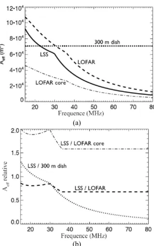
• The NenuFAR will also be a very large standalone instrument: it will have an effective area (and thus sensitivity) ~19 times larger than the LBA array of an international station, i.e. <70% to 85% of all LOFAR-LBA arrays, but this area will be instan-taneously and fully available during use, especial-ly in coherent tied-array (or phased-array) beam mode (TAB); by contrast, the coherent phasing of LOFAR-LBA array signals is limited to the 24 core stations that share the same reference clock (and have the same ionosphere above them); thus, the instantaneous sensitivity of the NenuFAR in coherent TAB mode will be 1.6 times better than the LOFAR-LBA one (Fig.4).
• Finally, in standalone mode, the NenuFAR will extend the observation bandwidth to significantly lower frequencies than the LBA range.
(a)
(b)
Fig. 4. Theoretical absolute (a) and relative (b) effec-tive collecting areas of NenuFAR between 15 and 80 MHz for NenuFAR (NenuFAR), the full LOFAR-LBA, the LOFAR core only and a typical 300m-diameter dish radio telescope (Arecibo).
The NenuFAR pointing will be controlled by a dedicated LCU (Local Command Unit) connected to 96 electronic modules, one in each LF tile, specifying the phasing scheme to be applied at any given time (different for each LF tile due to their random rota-tions); these modules are designed to be completely “radio-quiet” outside pointing time; pointing will oc-cur at intervals from 20 to 60 sec, ensuring low gain variation in the main beam direction. The NenuFAR LCU will be connected to the LOFAR LCU of station FR606. When NenuFAR will be used jointly with other LOFAR LBA arrays (so-called “International” mode), pointing orders will come from the LOFAR operations center via the LOFAR LCU and be trans-lated into LF tiles phasing commands by the Nenu-FAR LCU; data recorded by the LONenu-FAR backend will be sent to the LOFAR central correlator. In “Standa-lone” mode, pointing orders will come from a local command computer, and the data will be recorded locally.
3.2. STANDALONE USE WITH DEDICATED
RECEIVER
The standard NenuFAR concept consists of the 96 additional LF tiles and their phasing and command system, that are connected to the LOFAR backend of FR606. The contract of any European station owner with the International LOFAR Telescope board in-cludes the right to use that station in standalone mode for ~10% of the time. As the standard LOFAR station backend only allows to record low frequency-time resolutions observations (typically in 200 kHz in 1 sec bins), the full scientific exploitation of standalone NenuFAR observations requires either LOFAR's “Single Station” mode or a dedicated post-backend [6]. The former consists of a sub-array formed by a single station, which high-resolution data are sent to the central correlator for processing as TAB data. The latter is for example the ARTEMIS (Advanced Radio Transient Event Monitor and Identification System) post-backend dedicated to transients detection and study, that ingests high resolution station data and locally computes high-resolution time-frequency planes including parametric dedispersion [7].
If one wants to compute locally more than time-frequency planes with NenuFAR standalone data (e.g. auto- and cross-correlations of tile signals), then a dedicated receiver is necessary. Such a dedicated re-ceiver has been studied in the frame of the NenuFAR design study. It will consist of either a post-LOFAR-backend (ARTEMIS-like), or a fully independent backend. The LOFAR backend digitizes the LBA or NenuFAR tile signals, channelizes it in 200 kHz bands (called “subbands”), and computes beamform-ing within each subband. The beamformed signal of 244 subbands is sent to the LOFAR central correlator. The latter further channelizes (down to 0.76 kHz reso-lution) the signals of all subbands from all stations, and computes auto-/cross-correlations and/or incohe-rent or coheincohe-rent (adequately time-shifted) summation in order to produced polarized images and/or TAB data.
A post-LOFAR-backend dedicated receiver would ingest locally the station products (as does ARTE-MIS) and channelize, auto-/cross-correlate, and inte-grate them. A fully independent backend would perform the tasks of both the LOFAR backend and the central correlator, but in an optimized integrated way. A large computing power is required, but a prelimi-nary design study suggests that this is within the scope of new generation FPGAs. Additional “intelli-gent” processing like RFI mitigation or parametric dedispersion could be included. Transient Buffer Board data will also be processed in all cases. A dedi-cated receiver is important not only because it allows local, flexible processing, but primarily because it will greatly increase the duty-cycle of the NenuFAR stan-dalone use beyond the “guaranteed” 10% fraction of the time, albeit with some pointing constraints. With a post-LOFAR-backend receiver, usable in parallel to all NenuFAR observations (standalone or in
correla-tion with LOFAR LBA), the standalone analysis of NenuFAR data will be possible 100% of the time dur-ing which the NenuFAR tiles are connected to the FR606 backend, but the target will necessarily be within the 0.5°-3° NenuFAR beam fixed by the cur-rent LOFAR observation program. Conversely, with a fully independent backend that would process Nenu-FAR data in parallel with the standard station back-end, standalone mode becomes possible 100% of the time, whatever array (LBA, HBA or NenuFAR) is connected to the LOFAR backend. The only pointing constraint of this standalone NenuFAR mode is that the target must be located within the 10°-50° analog LF tile beam.
4. N
ENUFAR
P
ERFORMANCE ANDO
BSERVINGM
ODEThe final distribution of the 96 mini-arrays was set by the positioning constraints around the FR606 station and the power distribution over the entire field. Ne-nuFAR was divided in “petals” allowing a modular and flexible implantation of the instrument. Starting from the three prototype mini-arrays that were built during the design study, ~1/4 of the instrument (in fact 26 mini-arrays, defined as “NenuFAR-1”) is planned to be built before early 2015. The chosen mini-arrays provide a decent instrument PSF that will improve gradually with the construction of additional petals of the array while keeping the best azimuthal symmetry of the mini-array distribution (and there-fore, the azimuthal symmetry of the instrumental beam and interferometric coverage).
The expected performance of NenuFAR is com-pared to that of LOFAR in Fig.4 and a summary table of the instrumental characteristics, compared to other classical radio instrument can be found in Table 1. The expected sensitivities (for a 8-hour time integra-tion over the ~10-90 MHz) are 120-240 mJy for Ne-nuFAR-1, 50-100 mJy for the whole NenuFAR.
4. C
ONCLUSIONThe NenuFAR characteristics are compared to those of other existing international instruments in Table 1. In the European context, several instrumental projects are developed by LOFAR participants, such as ARTEMIS (from Oxford Univ., see above) or AARTFAAC (from Univ. Amsterdam – it aims at cross-correlating the 288 LBA and HBA signals from the 6 central LOFAR stations to perform permanent all-sky monitoring [8]).
NenuFAR is a LOFAR extension and a standalone instrument with emphasis on very high instantaneous sensitivity. We foresee it as an “Arecibo in Nançay”. It is also a SKA precursor for the French community, both scientific and technical (for SKA-low).
It is interesting also the operation of NenuFAR for the Universe studies in coordination with another ground-based and space low frequency instruments such as UTR-2, URAN, GURT, NDA, NRT, LOFAR,
P. Zarka, M. Tagger, L. Denis, J. N. Girard, A. Konovalenko et al.
International Conference on Antenna Theory and Techniques, 2015, Kharkiv, Ukraine SKA, LWA, Cassini, STEREO, FERMI, JUNO, HST,
Farside Explorer, etc.
R
EFERENCES1. Van Haarlem, M.P., Wise M.W., Gunst A.W. et al. 2013, ‘LOFAR: The Low Frequency ARray’, Astron. and Astrophys. 556,
2. Girard, J. N., Zarka, P., Tagger, M. et al. 2011, ‘Antenna Design and Distribution for a LOFAR Super Station in Nançay’ In: Planetary Radio Emissions VII. Austrian Acad. Sci. Press, Vienna. Ed. H. O. Rucker et al. 495-503.
3. Girard, J. N., Zarka, P., Tagger, M. et al. 2012, ‘Antenna design and distribution of the LOFAR Super Station’, C.R. Phys., 13, 33-37.
4. Boone, F. 2001, ‘Interferometric array design: Optimizing the locations of the antenna pads’ As-tron. and Astrophys. 377, 368-376.
5. Vasko, F. J., Barbieri, R. S., Rieksts, B. Q., Reit-meyer, K. L., and Stott Jr., K. L. 2002, ‘The cable trench problem: combining the shortest path and minimum spanning tree problems’ Computers and Operations Res., 29, 441-458.
6. Serylak, M., Karastergiou, A., Williams, C. et al. 2012, ‘Observations of Transients and Pulsars with LOFAR International Stations’, Proc. Elec-tromagnetic Radiation from Pulsars and Magne-tars Conf., Zielona Gora, Poland, 83-86.
7. Armour, W., Karastergiou, A., Giles, M. et al. 2011, ‘A GPU-based Survey for Millisecond Ra-dio Transients Using ARTEMIS’, Proc. ADASS XXI. Ed. P. Ballester and D. Egret. 33-37.
8. Prasad, P. and Wijnholds, S. J. 2012, ‘AART-FAAC: Towards a 24x7, All-sky Monitor for LO-FAR’, Proc. New Windows on Transients across the Universe, London, UK.
Table. 1. Characteristics of NenuFAR and NenuFAR-1 compared to those of large LF radio instruments (ob-serving below 100 MHz) existing or in project. (a) at 20 MHz, (b) at 30 MHz, (c) at 150 MHz.
Name Nantennas Effective area, (m2) Frequency range (MHz) Angle resolution (degrees) Nbeams Polarization type
NDA 144 4000(a) 10-110 11º (a) 1b 2 circ
UTR-2 2040 143000 8-32 0.5º 5b 1 lin
VLA 27 ~2000 73-74.5 0.5' 1b 2 circ
LWA 256 8000(a) 10-88 9º (a) 4bx20 MHz 2 lin
MWA 2048 ~2000(c) 80-300 3'(c) 1bx30 MHz 2 lin LOFAR- LBA 2688 72000 30-80 2''(b) 8b+nx4 MHz 2 lin NenuFAR-1 494 ~17000(b) 15-80 ~3º (b) 4bx65 MHz 2 lin NenuFAR Standalone 1824 62000(b) 15-80 1.5º (b) 4bx65 MHz 2 lin NenuFAR +LOFAR 4512 134000(b) 30-80 2''(b) 8b+nx4 MHz 2 lin

![[PDF] Télécharger Cours d Algorithmique et programmation en PDF | Cours informatique](data:image/gif;base64,R0lGODlhAQABAIAAAP///wAAACH5BAEAAAAALAAAAAABAAEAAAICRAEAOw==)