HAL Id: cea-02648603
https://hal-cea.archives-ouvertes.fr/cea-02648603
Preprint submitted on 29 May 2020
HAL is a multi-disciplinary open access
archive for the deposit and dissemination of sci-entific research documents, whether they are pub-lished or not. The documents may come from teaching and research institutions in France or abroad, or from public or private research centers.
L’archive ouverte pluridisciplinaire HAL, est destinée au dépôt et à la diffusion de documents scientifiques de niveau recherche, publiés ou non, émanant des établissements d’enseignement et de recherche français ou étrangers, des laboratoires publics ou privés.
CFD study of an innovative safety system for
pressurized water reactors
Thierry Cadiou, Elisabetta Stratta, Augier Loic
To cite this version:
Thierry Cadiou, Elisabetta Stratta, Augier Loic. CFD study of an innovative safety system for pres-surized water reactors. 2020. �cea-02648603�
CFD STUDY OF AN INNOVATIVE SAFETY SYSTEM FOR PRESSURIZED
WATER REACTORS
Thierry CADIOU, Elisabetta STRATTA, Loic AUGIER
CEA, DEN, DER, SESI
CEA Cadarache, F-13108, Saint Paul lez Durance, France
thierry.cadiou@cea.fr
ABSTRACT
After the FUKUSHIMA accident, passive systems become an important issue for the new projects of Pressurized Water Reactor (PWR). In response to the demands of his partners, the CEA has proposed suitable systems to deal with different accidental sequences. Then, it has dimensioned their components and modelled their integration in the reactor using the CATHARE2 system code. In particular, the CEA has worked on the ADS system (Automatic Depressurization System) devised to tackle with the well-known LOCA accident (Loss-of-coolant accident), resulting from a breach in the pipes of the primary circuit.
Concretely, the ADS system is made up of a tank called IRWST (In-Containment Refueling Water Storage Tank), placed high in the containment, which has the role of achieving a safety passive injection to replace the conventional one using low-pressure pumps, during a LOCA accident. The ADS is in fact already present on the AP1000 reactor, the US PWR designed to be totally passive. The CEA has proposed to improve it by adding a LPWT tank (Low-Pressure Water Tank) pressurisable by steam issued from the pressurizer on the last line of the ADS system. It should allow a better core cooling by the additional water injection in the reactor core, anticipated in time compared to that of the IRWST.
The study presented here exclusively focuses on the LPWT water pressurization phase prior to its injection into the reactor core. Three approaches are exposed:
- An analytical approach, in which one considers the pressurization of the volume of gas present in the tank without taking into account the liquid phase;
- A system approach with the CATHARE2 thermal-hydraulic code which allows to describe at the same time the volume of gas and the volume of liquid contained in the tank;
- A CFD approach using the NEPTUNE_CFD code to determine the local evolution of the quantities that characterize the system. This approach will notably make it possible to describe the movement of the interface and the velocity profile of the water vapor. It will also help to bring a better understanding of the physical phenomena involved during the LPWT water pressurization phase.
At the end, these different approaches show that the increase in pressure by the steam injection is an interesting option to pressurize the water tank. On the other hand, the results of the pressure evolution obtained by the system approach are very close to those obtained analytically, in the absence of liquid phase. However, they are overestimated compared to the CFD approach, which, thanks to a better modeling of the condensation of the injected vapor, leads to a more realistic evaluation.
KEYWORDS Pressurized Water Reactor, thermal-hydraulics, passive system, CFD, LOCA
1. Introduction
Among the different passive systems investigated by the CEA for future PWRs, the ADS system is dedicated to the LOCA accident. It aims at reducing in a first time the water pressure in the primary circuit, in the event of a loss of
primary coolant. Once reached, the IRWST tank located high up in the containment allows a passive water safety injection, by gravity, in the depressurized primary circuit in order to cool down the reactor core.
This existing system was first proposed on the AP1000 reactors. In order to improve this system, the CEA proposes to add a LPWT (Low-Pressure Water Tank) whose purpose is to allow an additional and anticipated injection of water, compared to that of the IRWST.
This LPWT pressurisation phase is modelled in this document by a Computational Fluid Dynamics (CFD) approach with the calculation NEPTUNE_CFD code [1]. The results obtained are compared with the analytical approach and with the CATHARE system code.
2. STATE OF THE ART 2.1 The LOCA accident
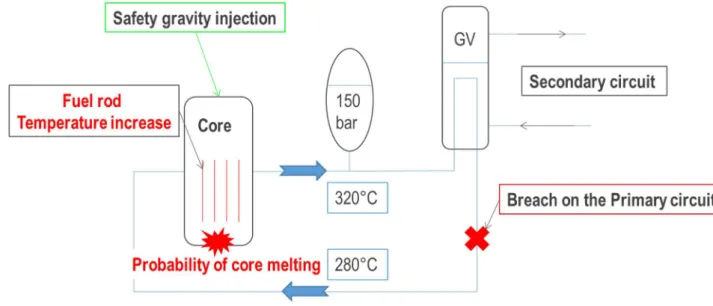
The LOCA accident is caused by a breach in the primary circuit (see Figure 1). This results in a loss of liquid water in it, which reduces the heat exchange in the reactor core. The fuel rods will rise in temperature that may cause their melting, entails a partial reactor core melting and jeopardize its integrity.
Figure 1: Description of a LOCA situation
To prevent core melting following a LOCA, the reactor is immediately stopped by rapidly falling down the control rods. It is then imperative to cool down the core at the earliest in order to evacuate the residual power by cold water injection. To achieve this, the primary circuit is first depressurized by the ADS system. The water present in the IRWST water tank can then be injected on a gravitational manner. The studied system is intended to anticipate the coolant injection.
2.2 The ADS passive system on the AP1000
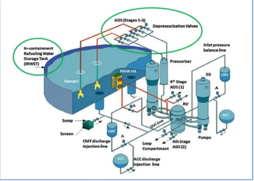
For the AP1000 [2], following a LOCA accident, the reactor core is cooled down with water from a tank of about 1000 m³ called IRWST. This tank is used to condensate the steam of the primary circuit formed by vaporization of the liquid water contained in the primary circuit following the decrease in pressure generated by the breach. The forced depressurization of the primary circuit is in fact ensured by four ADS lines that open one after the other. The first three lines are connected to the pressurizer and discharge into the IRWST [3]. The fourth line of the ADS is connected to one of the cold legs of the primary circuit and it discharges directly in the reactor vessel. The opening of this fourth ADS line takes place when the water of the primary circuit is essentially in the form of steam. In this way, the depressurization caused by the opening of this line ADS accelerates the depression of the primary circuit, making possible the gravitational injection of the water contained in the IRWST towards the reactor core [4] (see Figure 2).
Figure 2: Representation of the primary circuit of an AP1000
Although the depressurization by the fourth line is very effective, it does however have some disadvantages. Since this line is directly connected to the primary circuit in an area close to the core, this can lead to entrainment of the liquid water in the reactor vessel. The loss of liquid water inventory of the primary circuit entails a diminution of the cooling of the core, which would aggravate the accident. In addition, as this line discharges directly into the reactor vessel, the radiological inventory will increase.
The innovation proposed by the CEA for future PWR in order to overcome the disadvantages of this fourth ADS line (discharge of the primary circuit in the reactor vessel), is to position, not 3, but the 4 ADS lines between the pressurizer and the IRWST. However, this solution presents the major disadvantage of a slower depressurization of the primary circuit, resulting in a later injection of liquid water coming from the IRWST to the reactor core. The slower depressurization is due to the reduced critical flowrate, which is imposed by the smaller section of the pipe when it is placed on the pressurizer: the total equivalent section of the ADS pipes should not be greater than the pressurizer surge line section, because it would be useless.
The later injection of the IRWST results in a longer period during which the core is not cooled by any liquid water, thus leading to an abnormal heat of the fuel rod, which is not acceptable.
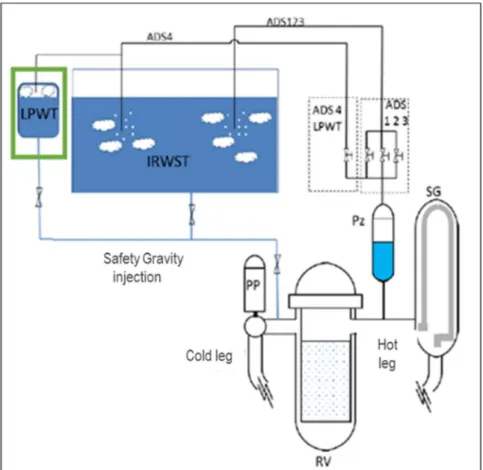
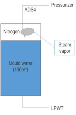
For this, the CEA proposes to add a smaller water tank (about 100 m³) called LPWT (Low Pressure Water Tank, see Figure 3) that will be pressurized by a part of the water vapor from this fourth ADS line during the forced depressurization phase. By this way, the LPWT water can be injected into the core, on an anticipated way, before the IRWST is operational.
Figure 3 : Passive safety system proposed by the CEA
3. NUMERICAL SIMULATION OF WATER VAPOR INJECTION IN THE LPWT 3.1 Analytical approach to system pressurization in the absence of a liquid phase
Following the previous LPWT presentation, we evaluate the pressurization by injection of water steam into a volume filled with non-condensable gas (nitrogen) whose walls are adiabatic (see Figure 4) [5].
Figure 4: Diagram of the reduced system
Steam is injected with an inlet temperature 𝑇 , an enthalpy ℎ , a velocity 𝑣 , and a mass flowrate 𝑄 . Initially, the tank of a constant volume V is at a temperature 𝑇 , a pressure 𝑃 . During the steam injection, the state of the system is described by its temperature T, its pressure P and its internal energy U.
If we consider the water vapor as an ideal gas, the pressure is expressed by:
𝑃 = . 𝑅. 𝑇 = . 𝑇 = . 𝑟. 𝑇 (1) With:
𝑃 : Tank pressure (Pa) 𝑉 : Tank volume (m³)
𝑇 : Injected gas temperature (K) 𝑚 : Gas mass in the tank (kg)
𝑟 = : Reduced ideal gas constant (J/kg/K)
By derivation of the ideal gas equation above, the variation of pressure in this volume is written:
∆𝑃 = . (∆𝑚. 𝑇 + 𝑚. ∆𝑇) with ∆𝑚 = 𝑄 . ∆𝑡 (2) With:
∆𝑃 : Internal pressure variation (Pa) ∆𝑚 : Variation of the vapor mass (kg) ∆𝑇 : Internal temperature variation (K)
𝑄 : Mass flowrate at the inlet of the tank (kg / s) ∆𝑡 : Time step (s)
After using simplification, based on the order of magnitude of the different physical quantities, the variation of the pressure per time step is written:
∆
∆ = . 𝑇 . 𝑄 (3)
3.2 LPWT pressurization system approach
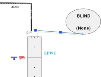
With the CATHARE system code [6], the LPWT is represented by a 0D volume, containing two meshes. One describes the vapor phase and the other the liquid phase [7]. These two meshes are separated by a rectilinear interface, non-deformable throughout the simulation, which simulates the level and moves up and down according to the evolution of the volume occupied by the liquid phase during the computation. The injection of water vapor by the fourth ADS line is represented by an axial, a 1D element, which is nothing other than a cylindrical pipe whose meshes are successive sections extruded along the axis (see Figure 5). An external boundary condition imposes the injection by defining the void fraction and the vapor/liquid flowrates and temperatures. A BLIND (adiabatic) condition is available to model a safety valve (by switching it to a pressure driven condition) for transients in which pressure would rise too much, but in this case, the computation is automatically stopped when the target pressure is reached.
Figure 5 LPWT CATHARE2 modelling 3.3 CFD Approach to LPWT pressurization
3.3.1 The NEPTUNE_CFD code
The calculation code NEPTUNE_CFD is a solver for solving multiphase flow problems [8]. It was developed by EDF, IRSN, FRAMATOME and CEA and relies on the numerical resolution of fluid dynamics equations in order to simulate fluid flows. The objective of this solver is to determine the evolution of the physical quantities of the fluids in each of the cells composing the domain. This makes it possible to obtain a local 3D description of the physical phenomena.
To describe the different phases of the system, NEPTUNE_CFD uses an Eulerian method with separate phases. It requires the solving of the Navier-Stokes equations for each of the phases present in the domain. This method is completed by physical models to describe the movement and heat exchange between these phases. In contrast to the Lagrangian method, the Eulerian method is based on the representation of the velocity vector field in each cell of the domain. The resolution does not follow the displacement of a fluid particle but the evolution of the different particle velocities that pass through a control volume [9].
3.3.2 The LPWT modelling
The LPWT is a cylindrical tank with a diameter of 3,5 m and a height of 10 m, hence a volume of 100 m³ (see Figure 6). The steam is injected at the top into the volume of non-condensable gas (nitrogen) via a 24 cm diameter pipe.
Figure 6: LPWT diagram
A preliminary study, not mentioned in this paper, showed that the pressurization of the system does not depend on the water depth but only on the initial gas height in the system. This is why the tank height is arbitrarily fixed in the following at 50 cm.
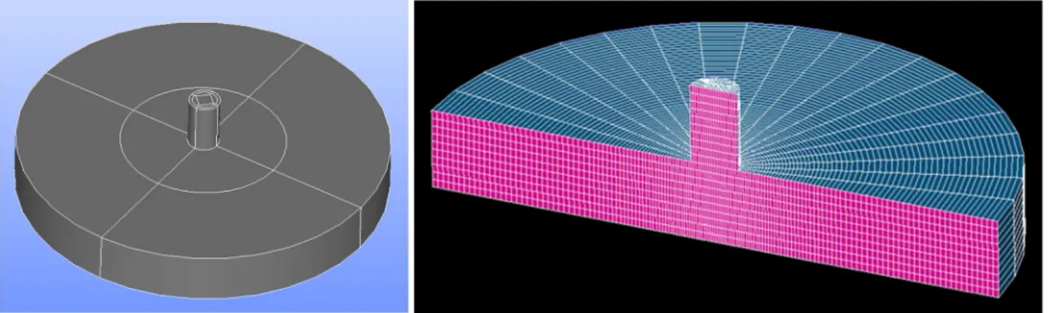
Using the SALOME tool [10], the LPWT is represented by the merging of two cylinders, cut into several blocks to allow an hexahedral meshing (see Figure 7) and a final meshing of the LPWT.
Figure 7: Geometry of the LPWT sectional view of the LPWT mesh
The calculation conditions used in a LPWT study are indicated on Figure 8.
Figure 8 : Initial and boundary conditions
4. PHYSICAL ANALYSIS OF THE RESULTS 4.1 LPWT analysis without liquid phase
In a first time, injection of steam into a volume of non-condensable gas without liquid water and closed by adiabatic walls is simulated.
The LPWT pressurization in the absence of liquid phase is evaluated by NEPTUNE_CFD calculation and the analytical relationship. The results of these two approaches presented Figure 9 are very close, with a difference lower than only 2 bar, i.e. 10%.
Figure 9: Temporal evolution of pressure in the LPWT between the NEPTUNE_CFD calculation in the absence of liquid phase and the analytical relationship
4.2 Analysis of LPWT in the presence of liquid phase 4.2.1 Sensitivity to the meshing
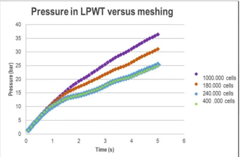
We are now interested in the global evolution of the pressure taking into account the liquid water. A sensitivity analysis of the number of meshes on the pressure evolution in the system is first performed (see Figure 10). The result obtained for meshes of 240,000 and 400,000 cells shows that the solution no longer depends on the chosen resolution. This converged solution will be used in the following.
Figure 10: Sensitivity of the mesh on the evolution of the pressure 4.2.2 Impact of the liquid phase on system pressurization
Comparing the pressure evolutions calculated using NEPTUNE_CFD with and without liquid phase (see Figure 19), we can see that the two configurations lead to different pressure evolutions.
Figure 11: Impact of the presence of the liquid phase on LPWT pressurization
The presence of water vapor thus modifies the evolution of the pressure in the system, following its condensation near the interface (see Figure 13). As a result of this condensation, the amount of gas increases more slowly, thereby reducing the pressure increase in the LPWT.
4.2.3 Confrontation of the evolution of the pressure between the two codes
By simulating with CATHARE the injection of water vapor in the LPWT with the same conditions as those of the NEPTUNE_CFD calculation, in the presence of liquid phase, it appears that the rise in pressure is attenuated for this one (Figure 12).
Figure 12 : Temporal evolution of pressure in the LPWT according to the calculation code
As a part of water vapor condenses with the CATHARE calculation, but in very small amount compared to that of the NEPTUNE_CFD calculation, pressure evolution differs between these two calculations.
Figure 13 indeed shows that four times less water is condensed with the CATHARE than with NEPTUNE_CFD (10 kg of water condensed on CATHARE against 40 kg on NEPTUNE_CFD), but the difference is only significant after 1 second.
Figure 13 : Condensation caused by the presence of the liquid phase
As a conclusion, The CATHARE evaluation is therefore sufficient to describe the water pressurization of the water provided that this phase is short.
4.2.4 Local study of condensation in LPWT with NEPTUNE_CFD
To explain the differences in condensation, the evolution of the liquid-vapor interface is studied in more detail with the CFD approach. At the beginning of the simulation, the interface deforms under the action of water vapor (see Figure 14, left). Following water vapor jet on the free surface, the strong deformation of the interface expels a fraction of the liquid water upwards (see Figure 14, right).
Figure 14: Position of the interface at t = 0.55 s (left) and t = 0.72 s (right)
As the mass flowrate is imposed, the progressive increase of the pressure of the water vapor combined with that of its density leads to the reduction of the velocity of the inlet vapor. The interface is therefore less and less deformed by the impact of water vapor as the transient progresses (see Figure 15).
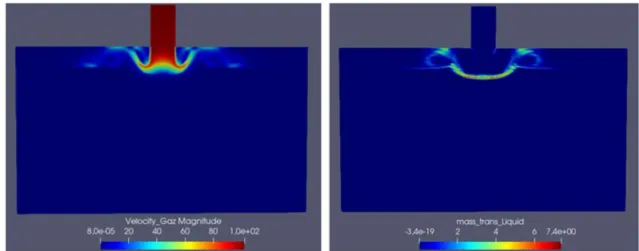
The movements of the interface result in the increase of the exchange surface and heat exchanges. The vapor pressure locally exceeds the saturation conditions and leads to local condensation. With the NEPTUNE_CFD software, it is possible to visualize the evolution of the size "mass transfer liquid". This quantity represents the liquid water resulting from the condensation of the water vapor. By this way, the preferential zone of condensation is highlighted on Figure 16.
Figure 16: Velocity profile and liquid mass transfer in the LPWT at t = 0.05s
In the first moments, even if the interface is strongly deformed, there is little condensation on the entire interface. It tends to focus in the area of impact of the water vapor. This is explained by the fact that the entire gas range is still relatively unaffected by the steam injection (see Figure 17).
Figure 17 : Velocity profile and liquid mass transfer in the LPWT at t = 0.57s
During the period during which the deformation of the interface stabilizes, the water vapor condenses all along the interface as well as in the zones of turbulence. Liquid mass transfers are then less important than in the previous situation (water jet close to steam injection) but covers the entire interface (see Figure 18).
5. CONCLUSION AND PROSPECTS
The CEA has proposed to improve the ADS safety passive system designed for the AP1000 in case of a breach on the primary circuit. Installing on this system an additional water tank called LPWT contributes to an improved and quicker cooling of the reactor core. By three different approaches, it has been shown that its water pressurization by injecting water vapor from the pressurizer is a relevant option.
The pressurization predicted by the CATHARE system code is similar to that calculated analytically. The CFD modelling evidences that water condensation becomes significant after a few seconds. During the first moments, the pressurization evaluated by the CATHARE system code and CFD approaches are also similar. If the pressure threshold is quickly reached to activate the injection in the primary circuit, the system approach is therefore appropriate to describe the water tank pressurization.
However, since the CATHARE modeling partially takes into account the vapor condensation in the LPWT, it tends to overestimate the pressure increase obtained by the CFD approach. On the other hand, one gets with NEPTUNE_CFD a very marked condensation that slows the pressurization of the water contained in the tank. This CFD approach also makes it possible to better model the movements of the interface and to analyze the effects of turbulence, which favor thermal exchanges between the liquid and vapor phases.
As a perspective, the flexibility of CFD will help to optimize the LPWT tank geometry. For instance, the position of the injector on the pressurization could be evaluated, within the objective to decrease water condensation.
6. NOMENCLATURE
Abbreviation Definition Variable Definition
CEA French Commission for the Atomic Energy and Alternative Energy 𝑃 Tank pressure (Pa)
ACC ACCumulator 𝑉 Tank volume (m³)
ADS Automatic Depressurization System 𝑇 temperature (K) Injected gas
LOCA Loss-of-coolant accident M Gas mass in the tank (kg)
AP1000 Advanced Passive Reactor (electrical power of 1000 MW) 𝑟 =𝑅 𝑀
Reduced ideal gas constant (J/kg/K) CATHARE Advanced software for system thermal-hydraulics ∆𝑃 Internal pressure variation (Pa)
CFD Computational Fluid Dynamics ∆𝑚 Variation of the vapor mass (kg)
CMT Core Make-up Tank ∆𝑇 Internal temperature variation (K)
IRWST In-containment Refueling Water Storage Tank 𝑄 inlet of the tank (kg/s) Mass flowrate at the
LPWT Low Pressure Water Tank ∆𝑡 Time step (s)
PWR Pressurized Water Reactor
REFERENCES
1. J. Lavieville, E. Quemarais, L. Boucker, « NEPTUNE_CFD user guide » 2010. https://www.code-saturne.org/cms/neptune-cfd
2. AP1000 : http://www.westinghousenuclear.com/new-plants/ap1000-pwr
3. NRC, AP1000 Passive Safety System : https://www.nrc.gov/docs/ML1523/ML15230A043.pdf
4. M.C. Smith, R.F. Wright, Westinghouse “Small Modular Reactor Passive Safety System Response to Postulated Events”, Proceedings of ICAPP’12 Chicago, USA, June24-28 1012, paper 12157.
5. M. Hosseini, I. Dincer, G.F. Naterer, M.A. Rosen, University of Ontario Institute of Technology, Oshawa, , Canada,”Thermodynamic analysis of filling compressed gaseous hydrogen storage tanks”, International Journal of Hydrogen Energy, Volume 37, Issue 6, March 2012, Pages 5063-5071.
6. G. Geffraye and al., “CATHARE 2 V2.5 2: A single version for various applications,” Nuclear, Engineering and Design, vol. 241, pp. 4456-4463, 2011.
7. The CATHARE code strategy and assessment. F. Barré and M. Bernard. Nuclear Engineering and Design, 124(3):257-284, 1990.
8. A. Guelfi, D. Bestion, M. Boucker, P. Boudier, P. Fillion, M. Grandotto et al. (2007). “NEPTUNE - a new software platform for advanced nuclear thermal-hydraulics”. Nuclear Engineering and Design, 156, 281–324. 9. J. Lavieville, P. Coste. “Numerical modeling of liquid-gas stratified flows using two phase Eulerian approach”.
Proceeding of 5th International Symposium on Finite Volumes for Complex Applications, Aussois, France, June 08–13, 2008.