HAL Id: tel-01729186
https://tel.archives-ouvertes.fr/tel-01729186
Submitted on 12 Mar 2018HAL is a multi-disciplinary open access archive for the deposit and dissemination of sci-entific research documents, whether they are pub-lished or not. The documents may come from teaching and research institutions in France or abroad, or from public or private research centers.
L’archive ouverte pluridisciplinaire HAL, est destinée au dépôt et à la diffusion de documents scientifiques de niveau recherche, publiés ou non, émanant des établissements d’enseignement et de recherche français ou étrangers, des laboratoires publics ou privés.
positrons and study of positronium production in the
GBAR experiment
Amelia Mafalda Maia Leite
To cite this version:
Amelia Mafalda Maia Leite. Development of a buffer gas trap for the confinement of positrons and study of positronium production in the GBAR experiment. Nuclear Experiment [nucl-ex]. Université Paris Saclay (COmUE), 2017. English. �NNT : 2017SACLS380�. �tel-01729186�
NNT : 2017SACLS380
THÈSE DE DOCTORAT
de l’Université Paris-Saclay
Preparée à l’Université Paris-Sud,
au sein du Département de Physique des Particules, Irfu, CEA Saclay
ÉCOLE DOCTORALE N°576
Particules, Hadrons, Énergie, Noyau, Instrumentation, Imagerie, Cosmos et Simulation (PHENIICS) Spécialité de doctorat : Physique des particules
Par
Amélia Mafalda Maia Leite
Development of a buffer gas trap for the
confinement of positrons and study of positronium
production in the GBAR experiment
Thèse presentée et soutenue à Saclay, le 27 octobre 2017 Composition du jury :
M. Daniel Comparat Directeur de Recherche Président du jury Université Paris-Sud
M. Michael Charlton Professeur Rapporteur Université de Swansea
Mme Martina Knoop Chargée de Recherche Rapporteur Université d’Aix-Marseille
M. Paolo Crivelli Chercheur Examinateur ETH Zurich
M. Pierre Vanhove Ingénieur-chercheur Examinateur CEA Saclay
M. Yves Sacquin Directeur de recherche Directeur de thèse CEA Saclay
M. Dirk van der Werf Professeur Co-encadrant de thèse Université de Swansea
Pedra Filosofal
Eles não sabem que o sonho é tela, é cor, é pincel, base, fuste, capitel, arco em ogiva, vitral, pináculo de catedral, contraponto, sinfonia, máscara grega, magia, que é retorta de alquimista, mapa do mundo distante, rosa-dos-ventos, Infante, caravela quinhentista,
que é cabo da Boa Esperança, ouro, canela, marfim,
florete de espadachim, bastidor, passo de dança, Colombina e Arlequim, passarola voadora, pára-raios, locomotiva, barco de proa festiva, alto-forno, geradora, cisão do átomo, radar, ultra-som, televisão, desembarque em foguetão na superfície lunar.
Eles não sabem, nem sonham, que o sonho comanda a vida, que sempre que um homem sonha o mundo pula e avança
como bola colorida
entre as mãos de uma criança.
Acknowledgements
I am grateful to have shared almost four years of my life with the GBAR group at Saclay, and to have had the privilege of building a 3 meter apparatus with my own hands. During this journey, I have grown immensely both professionally and personally, and I have met outstanding people along the way.
First of all, I would like to thank Patrice Perez who was my first contact with the group. His persuasive arguments convinced me to embark in the GBAR endeavor and his attention ensured my journey was smooth. I thank Yves Sacquin for taking me as his student. I am grateful to László Liszkay for his hard work in keeping the LINAC (the whole lab for that matter) alive, and for all his assistance and wise advice.
I am specially in debt to Bertrand Vallage for teaching me the art of “bricolage”, which is indeed a paramount skill to be a good experimental physicist. Bertrand always looked out for me and brought good humor to the lab. He was instrumental in assembling the electrodes of the trap and in fixing my mistakes. Thank you Bertrand, you will be missed!
I thank Jean-Marc Reymond for his dedication to the GBAR experiment. His clever ideas and hands-on approach were invaluable to reach the landmark of getting the Riken and buffer gas traps ready to be moved to CERN.
Je remercie chaleureusement Thomas Dalla-Foglia pour sa assistance à la construc-tion du piège et pour corriger mes erreurs comme quand j’ai coincé une vis dans une électrode. Aussi, merci pour le merveilleux cadeux de soutenance!
I thank Pauline Comini for the valuable discussions we had about the ANTION project and for the times we shared chocolate flavored with tonka bean.
I had the pleasure to share the office with BongHo Kim during the last year of my thesis. BongHo was invaluable in developing the GEANT4 simulation and taught me almost everything I know about detector physics. I am particularly grateful for the discussions we had about the results of my thesis and for patiently answering my every-minute questions. Everyday we shared the bus ride home during which he patiently listened to my end-of-thesis rants and always proposed witty and funny advice. Thank you BongHo!
I wish good luck to Barbara Latacz, who recently joined the endeavor and who hopefully will see the production of ¯H+. A PhD is a marathon, not a sprint. I hope your adventure in GBAR is fruitful and make sure to do physics above else!
I would additionally like to thank Fanny Jambon for the helpful discussions about the SiC chapter, and for making the last few months of the journey more bearable with her funny remarks.
against time to build a three meter apparatus with little technical support or man-power. We spent countless hours on the floor tightening screws, cabling or dialing oscilloscopes. His optimism always kept me hopeful even in dire straits (“the LINAC is broken again!”) and his not-so-funny jokes always eased the pressure of the race. With long calls and heated discussions, Dirk closely supervised the writing of this dis-sertation, even taking time off his holidays to discuss each and every correction to the manuscript. Suffice to say that Dirk made me the experimental physicist I am today, and I am strongly in debt for all his effort and guidance. I will treasure the time we worked together and all the knowledge he imparted to me. And yes, I will use my brain!
I am also grateful to the jury members, specially Professor Charlton and Dr. Criv-elli, for generously taking the time to read this manuscript and providing valuable comments and corrections, thus contributing to the improvement of this thesis.
I thank Nathalie Besson, my CEA marraine, for keeping a watchful eye on me and advocating for my interests.
My friends Kanna, Anirudh, Sviatoslav, Satya, Carolyna, Juliane and Inna, with whom I shared my life as a PhD student, were extremely supportive and made me feel I was not alone in this endeavor. I thank them for listening to my rehearsals and for cheering me up every step of the way.
Mãe, Pai e Bruno, parece que toda a minha infância foi planeada para culminar nesta tese. Todas as explicações de ciência, todas as visitas a museus, todos os livros lá em casa... Sem dúvida vocês fizeram a cientista que sou hoje e por isso vos agradeço. Obrigada pelo vosso apoio quando decidi ir estudar para mais longe e por todos os conselhos e entusiasmo durante este longo percurso.
Rajiv, I will make my acknowledgments short so that I don’t end up writing more pages than the physics content in this thesis. You inspired me to follow in your footsteps and pursue the experimental physics path with your everyday excitement about turning on six lasers, your ultra-high vacuum apparatus, being able to see a rubidium cloud with the naked eye, and single photon interactions. Yet you forgot to tell me that machines break and that Nature makes the life of experimental physicists hard; approximations do not work so well in real life after all. I thank you for all your support during these years, for literally making me write this manuscript and for listening to all my rehearsals (5? who was counting?). The last year was particularly grueling, but your patience and contagious optimism are the reason you can now call me a doctor! Thank you for sharing with me the joy of my successes and for comforting me in my failures. Without a doubt this thesis would not have been possible without you.
Contents
List of Figures vii
List of Tables xi
Résumé de la thèse xv
I
The GBAR Endeavour
1
1 A brief history of antimatter 3
2 Gravitational Behaviour of Antihydrogen at Rest 7
2.1 The GBAR experiment . . . 8
2.1.1 H¯+ production and the ANTION project . . . 9
2.1.2 H¯+ cooling and the ¯g measurement . . . 13
2.2 GBAR challenges and competition . . . 15
2.3 Thesis outline . . . 17
II
A positron bottle Enterprise
19
3 Positron source and transport 21 3.1 Positron sources . . . 213.2 The positron source at Saclay . . . 22
3.3 Positron beam characterization . . . 25
3.3.1 Electrons . . . 25
3.3.2 Positron beam parallel energy distribution . . . 27
4 Buffer gas trap 31 4.1 Ideal Penning trap . . . 32
4.2 Buffer gas trap . . . 35
4.2.1 Rotating wall technique . . . 37
4.3 Apparatus description . . . 41
4.3.1 Vacuum System . . . 44
4.3.2 Magnetic Field . . . 47
4.3.3 Detection and diagnostics . . . 48
4.3.5 Data acquisition. . . 56
4.4 Conclusion . . . 59
5 Buffer gas trap accumulation experiments 61 5.1 First and second stage trapping . . . 62
5.1.1 Positron trapping technique . . . 62
5.1.2 Positron beam parallel energy distribution . . . 64
5.1.3 Buffer gas pressure effect . . . 69
5.1.4 Cooling gas effect . . . 74
5.1.5 Rotating Wall experiments . . . 76
5.1.6 Parallel energy distribution . . . 81
5.2 Third stage accumulation . . . 85
5.2.1 Third stage capture optimization . . . 85
5.2.2 First well . . . 89
5.2.3 Second well . . . 90
5.3 Characterization of the positron beam . . . 96
5.3.1 Time distribution . . . 96
5.3.2 Energy distribution . . . 97
5.3.3 Radial profile . . . 97
5.4 Conclusion and outlook. . . 98
III
The hydrogen cross section Challenge
101
6 Reaction cavity simulations 103 6.1 The ANTION project. . . 1046.1.1 Reaction Cavity . . . 106
6.1.2 Detection and diagnostics . . . 109
6.2 Simulation description . . . 110
6.2.1 Positron beam. . . 110
6.2.2 Positronium formation . . . 111
6.2.3 Positronium annihilation . . . 112
6.3 Results of the simulation . . . 116
6.3.1 Hydrogen production . . . 116
6.3.2 Ortho-positronium density distribution in the cavity. . . 118
6.3.3 Angular distribution . . . 118
6.4 Background estimation . . . 121
6.5 Conclusion and outlook. . . 125
IV
reDiscovery of a positron moderator
127
7 Study of a positron moderator 129 7.1 Positron moderation . . . 1307.2 Silicon carbide . . . 131
7.3 Experimental setup . . . 132
CONTENTS
7.4.1 Work function . . . 134
7.4.2 Energy distribution . . . 134
7.4.3 Positron re-emission yield and diffusion length . . . 136
7.4.4 Doppler broadening spectroscopy . . . 139
7.5 Applications of a 4H-SiC remoderator . . . 143
7.6 Conclusion . . . 144
V
Conclusion
147
List of Figures
1.1 A picture of a positron passing through a lead plate in a Wilson Cloud
Chamber. . . 4
2.1 Comparison of the global ¯H+ production cross sections for different positronium excitation levels. . . 11
2.2 Comparison of the experimental results of Merrison et al. and three different cross section models. . . 13
2.3 A preliminary drawing of the free fall chamber, Micromegas and time-of-flight detectors. . . 14
3.1 Linac schematic drawing and picture . . . 23
3.2 Positron target . . . 24
3.3 Tungsten moderator . . . 24
3.4 Positron beam on a MCP. . . 26
3.5 Image of the electron and positron beam on the MCP assembly. . . 27
3.6 Energy distribution along the beam line. . . 28
4.1 Schematic drawing of a section of a Penning trap. . . 33
4.2 Motion of a charged particle in a Penning trap. . . 34
4.3 Diagram of Surko’s three stage positron accumulator. . . 35
4.4 Cross sections for positron impact excitation of the a1Π electronic state of N2 and positronium formation. . . 36
4.5 Dipolar electric potential produced by a four segment rotating wall for different times. . . 41
4.6 Illustration of the accumulation technique. . . 42
4.7 Detailed view of the buffer gas trap electrodes . . . 43
4.8 The axial electrical potential and applied magnetic field in the first and second stage. . . 44
4.9 Diagram of the vacuum system . . . 45
4.10 Schematic overview of the vacuum chambers and accumulator electrodes together with the magnetic coils. . . 49
4.11 Schematic drawing of the operation of a microchannel plate detector. . 51
4.12 Drawing of the MCP assembly. . . 52
4.13 The front panel of the LabVIEW program that monitors and adjusts the buffer and cooling gas pressure. . . 53
4.14 The front panel of the LabVIEW program that allows the monitor-ing of the pressure and the control of the vacuum pumps, valves and
coils/solenoids’ power supplies. . . 55
4.15 Schematic overview of the setup that controls the electrodes’ bias. . . . 57
4.16 Sequence editor Labview program.. . . 58
4.17 The buffer gas trap currently working at Saclay. . . 59
5.1 Schematic diagram of the axial electrical potential of the first and second stage during the trap-close injection-ejection sequence. . . 65
5.2 Accumulation curve . . . 66
5.3 Positron beam parallel energy distribution at the entry of the buffer gas trap. . . 67
5.4 Positron beam dimensions at the entry of the buffer gas trap.. . . 68
5.5 Axial electric potential for moderator at 133 G and 333 G. . . 69
5.6 Accumulation curve for moderator at 133 G and 333 G . . . 70
5.7 Number of particles in the trap as a function of accumulation time for different N2 pressures. . . 70
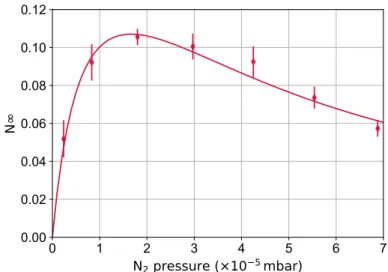
5.8 Trapping rate, loss rate and lifetime as a function of nitrogen pressure . 72 5.9 N∞ as a function of nitrogen pressure. . . 73
5.10 Cooling gas effect . . . 74
5.11 The positron trapping and loss rate as a function of the SF6 gas pressure. 75 5.12 Rotating wall effect on the trapping rate and positron lifetime in the second stage. . . 76
5.13 Effect of the rotating wall direction of rotation. . . 78
5.14 Rotating wall frequency scan for several amplitudes. . . 79
5.15 Estimation of the central frequency. . . 80
5.16 Image of positron cloud and respective intensity curve for three rotating wall frequencies. . . 82
5.17 Configuration of the axial electrical potential during the measurement of the parallel energy distribution. . . 83
5.18 Parallel energy distribution of the positrons trapped in the second stage. 84 5.19 Schematic diagram of the axial electrical potential during the positron accumulation in the third stage. . . 86
5.21 Transfer time between the first and the second stage for 4 and 5 electrode well. . . 87
5.20 Optimization of the transfer time between the first and the second stage. 88 5.22 Optimization of the potential depth of the first well of the third stage.. 89
5.23 Optimization of the time during which the rotating wall is applied in the first well of the third stage. . . 90
5.24 Third stage accumulation curve. . . 91
5.25 Rotating wall three frequency scan for two well lengths. . . 92
5.26 Rotating wall three amplitude scan. . . 94
5.27 Positron cloud radius as a function of the number of stacks and number of positrons . . . 95
5.28 Temporal distribution of the positron beam ejected from the third stage of the buffer gas trap.. . . 96
LIST OF FIGURES
5.29 Image of the positron beam ejected out of the third stage. . . 98
6.1 Schematic drawing of the ANTION apparatus. . . 105
6.2 CAD drawing of the reaction chamber . . . 106
6.3 Time distribution of the positron beam ejected from the third stage of the buffer gas trap and the bunched beam . . . 107
6.4 Pictures of the reaction cavity. . . 108
6.5 Pictures of the SiO2 mesoporous film. . . 109
6.6 Positron beam time and spatial distribution. . . 111
6.7 Ortho-positronium energy distribution. . . 112
6.8 Energy distribution of simuated γ-ray photons resulting from the anni-hilation of ortho-positronium in vacuum. . . 113
6.9 Simulated time distribution of ortho-positronium decay. . . 114
6.10 Simulation geometry. . . 115
6.11 Number of hydrogen atoms produced per positron pulse. . . 117
6.12 Spatial distribution of the ortho-positronium annihilation point. . . 120
6.13 Simulated deposited energy in the dectector as a function of time. . . . 122
6.14 Simulated deposited energy in the detector as a function of time for the background signal. . . 123
6.15 Deposited energy spectrum for compton scattering. . . 124
6.16 Deposited energy spectrum of γ-ray photons resulting from the annihi-lation of ortho-positronium. . . 124
7.1 Schematic diagram of some of the processes that occur when positrons interact with matter. . . 131
7.2 Schematic diagram and picture of the experimental setup used in the SiC measurements. . . 133
7.3 Annihilation signal upon implanting positrons in the epitaxial layer and substrate. . . 135
7.4 Definition of positron re-emission yield. . . 136
7.5 Positron re-emission yield as a function of the voltage difference between the tube and the SiC sample for the epitaxial layer and the substrate, and respective energy distribution. . . 137
7.6 Positron re-emission yield as a function of the beam energy for the epi-taxial layer and the substrate. . . 138
7.7 Typical spectrum of a defect free material and a material containing open volume defects. . . 140
7.8 S and W parameter as a function of the positron beam energy and the mean implantation depth. . . 142
7.9 S-W map of the epitaxial layer and substrate. . . . 143
List of Tables
4.1 Positron interactions with a nitrogen molecule and respective threshold energy. . . 37
4.2 Positron annihilation time and cooling time for some molecular gases . 39
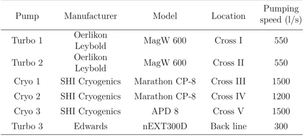
4.3 Summary of the vacuum pumps used in the buffer gas trap. . . 46
4.4 Estimated and measured pressure along the accumulator when the buffer gas is present. . . 48
5.1 Typical potentials applied to the first and second stage electrodes during trapping and ejection. . . 63
5.2 The potentials applied to the first and second stage electrodes during trapping and ejection. These potentials were optimized with a magnetic field at the moderator position of 333G G. . . 69
Résumé de la thèse
GBAR - Gravitational Behaviour of Antihydrogen at Rest
Le principe d’équivalence faible stipule que la trajectoire d’une particule est indépen-dante de sa composition et de sa structure interne lorsqu’elle est soumise à une force gravitationnelle. GBAR (Gravitational Behaviour of Antihydrogen at Rest) est une expérience qui vise à mesurer l’accélération des atomes neutres d’antihydrogène ( ¯H) en chute libre dans le champ gravitationnel terrestre, pour tester le principe d’équivalence avec l’antimatière. La température des atomes d’antihydrogène, donnée par la distri-bution de ses vitesses initiales, est la principale source d’erreur dans cette expérience. Par conséquent, pour réduire cette incertitude des atomes ultra-froides de ¯H sont néces-saires.J. Walz et T. Hänsch ont proposé que les ions ¯H+, un système lié d’un antiproton et de deux positons, puissent être refroidis à des températures de microkelvins, cor-respondant à des vitesses de m/s. L’avantage d’utiliser des ions ¯H+ est que ceux-ci peuvent être refroidis par refroidissement sympathique avec des ions de matière, tandis que la répulsion de Coulomb empêche leur annihilation. Après avoir été refroidi, le positon en excès peut être photo-détaché pour la mesure du temps de chute libre de l’anti-atome neutre.
L’accélération gravitationnelle de ¯H, ¯g = m¯g ¯
mig sera mesurée en déterminant la in-tervalle de temps entre le photo-détachement du positon excédentaire, et l’impact de
¯
H sur un plan d’annihilation après sa chute, ∆t. Le laser de photo-détachement définit le départ de la chute libre, tandis que l’arrêt est défini par la détection des pions qui résultent de la annihilation des antiprotons. L’équation qui décrit le mouvement de chute libre est:
∆z = 1 2g∆t¯
2
+ v0,z∆t , (1)
où ∆z est la distance de chute connu avec précision, et v0,z la vitesse verticale initiale après le photo-détachement. Avec ¯H à 1 neV, 1500 annihilations seront nécessaires pour obtenir une précision de 1% sur ¯g.
Deux ingrédients sont essentiels pour produire des ions ¯H+: les antiprotons et les atomes de positronium (système lié positon-électron); et deux réactions: la production d’antihydrogène, qui en combinaison avec une autre atome de positronium produisent
¯ H+:
¯
où ¯p est l’antiproton, Ps le positronium et ¯H l’atome d’antihydrogène. L’étoile désigne l’excitation de l’atome de positronium ou de l’atome d’antihydrogène.
Le projet ANTION est un sous-projet de GBAR qui vise à produire et étudier, pour la première fois, l’ion antihydrogène formé selon ces deux réactions Néanmoins, la première phase du projet implique la mesure de la section efficace sur la matière, à savoir la réaction conjugués de charge
p + Ps∗ → H∗+ e+, (4)
et la réaction à quatre corps
H∗+ Ps∗ → H−+ e+. (5)
Les étapes nécessaires à la réalisation de l’expérience de gravitation peuvent être résumées comme suit:
1. Production d’un flux intense de positons (antiélectrons) rapides à partir des interactions d’un faisceau d’électrons de 10 MeV, produite par un accélérateur linéaire, avec une fine cible de tungstène .
2. Modération des positons jusqu’à quelques eV par une cible de tungstène, formant un faisceau avec un flux 3×10⁸e+/s.
3. Piégeage de positons à l’aide d’un piège àbuffer gas.
4. Accumulation des positons dans un piège Penning-Malmberg à haut champ magnétique et formation d’un plasma dense avec 1010 positons.
5. Production de positronium: les positons sont focalisés dans une cavité recou-vert d’un conrecou-vertisseur positon-positronium en silice nanoporeuse, afin de former un nuage dense de positronium.
6. Excitation des atomes de positronium pour augmenter la section efficace de production des anti-ions.
7. Production de ¯H+: des atomes de positronium interagissent avec un faisceau d’antiprotons d’énergie très faible délivré par l’anneau de décélération ELENA (Extra Low ENergy Antiproton ring) produisant les atomes et l’ions d’antihydrogène. 8. Capture des ions et refroidissement à 10 µK.
9. Mesure de ¯g: photo-détachement du positon excédentaire et mesure de la chute libre de l’atome d’antihydrogène.
Organisation de cette thèse
L’objectif principal de cette thèse était de développer certains outils nécessaires pour la mesure des sections efficaces totales de production d’hydrogène, dans le cadre de la collaboration GBAR. Ces outils comprennent un piège à buffer gas à trois étages pour le piégeage et l’accumulation de positons, et une simulation de Monte Carlo de la distribution temporale et spatiale des atomes de positronium dans la cavité de réaction. Le reste de cette thèse est organisé comme suivant:
• La partie II est consacrée à la production et accumulation de positons dans le piège à buffer gas. La source de positons et la ligne de transport présentes à Saclay sont décrit dans le Chapitre 3. Le Chapitre 4 fournit quelques outils théoriques nécessaires pour comprendre le principe de fonctionnement d’un piège à positons et un aperçu historique du piège Penning, dans lequel ce piège est basé. Ce chapitre comprend ainsi, une description du piège qui a été construit au cours de cette thèse. Le Chapitre 5 dévoile le travail expérimental mené pour optimiser le piège. Il décrit les protocoles de piégeage et les procédures d’optimisation conçus pour augmenter la performance du piège, ainsi que l’étude de l’effet du gaz tampon et et du gaz de refroidissement, et l’application de la technique rotating wall.
• La partie III présente une simulation de Monte Carlo développée pour éval-uer l’évolution temporale et spatiale des atomes de positronium dans la cavité où les collisions antiproton-positronium auront lieu. Une estimation du nom-bre d’atomes d’hydrogène produits en fonction de l’énergie incidente des pro-tons est donnée, selon les section efficaces théorétiques de formation d’hydrogène. En outre, une suggestion est proposée afin d’augmenter le nombre d’atomes de positronium dans la cavité.
• La partie IV comprend l’étude d’un modérateur de positons - un matériau qui émet positons lents à l’impact avec un faisceau de positons. Premièrement, une brève introduction en ce qui concerne la physique de la modération de positons est donnée, suivie d’une description de la configuration expérimentale utilisée dans cette étude. Les mesures de la work function et la longueur de diffusion d’une couche épitaxiée sont rapportés, ainsi comme l’efficacité de modération. Ce travail est étroitement lié à l’expérience GBAR car il peut potentiellement augmenter l’efficacité du piégeage de positons.
• La partie V conclut cette thèse en résumant les résultats obtenus et en four-nissant quelques suggestions pour le progrès futur du travail décrit.
Le piège développé pour GBAR est un piège de type Penning-Malmberg constitué d’une série d’électrodes cylindriques de différent diamètres. Ceux-ci forment trois étages dis-tinctes de piégeage avec trois régions de pression. Les positons sont confinés radialement par un champ magnétique statique produit par des solénoïdes et bobines, et longitudi-nalement par des électrodes qui produisent des potentiels électrostatiques. Le principe de ce piège est que les positons entrants perdre leur énergie à travers des collisions inélastiques avec un gaz tampon qui est introduit dans le première étage du piège. Pendant qu’ils se refroidissent, ils sont piégés dans les potentiels progressivement plus profondes, et une pression progressivement plus faible, jusqu’à ce que les positons sont confinés sur la région de pression la plus basse du piège - étage 3, où la durée de vie des positons est plus longue.
Afin de piéger les positons avec quelques dizaines d’électrons-volts, ils doivent perdre énergie suffisante pour qu’ils ne sortent pas du piège, une fois qu’ils sont réfléchis par la fin barrière potentielle. Le mécanisme de refroidissement utilisé dans ce type de pièges est les collisions inélastiques subit un positon avec le gaz tampon. Le gaz tampon plus efficace est l’azote moléculaire.
L’objectif principal des expériences réalisées était de mettre au point le piège nou-vellement construit. Cela incluait l’étude de protocoles de piégeage, des effets du gaz tampon et du gaz de refroidissement sur le taux de piégeage et la quantification de la demi-vie des positons. La fréquence et l’amplitude de la rotating wall ont été op-timisées pour chaque puits de potentiel et la compression du nuage de positons a été obtenue, prolongeant ainsi la demi-vie des positons. Le faisceau de positons formé par le troisième étage était caractérisé, notamment la distribution temporelle et le profil radial. Le nombre maximum de positons piégés dans le premier et deuxième étage était 4.6×10⁴, tandis que le nombre maximal de positons piégés dans la troisième étage était de 1.2×10⁵, correspondant à une accumulation totale de 10 s. La première et la deux-ième étage fonctionnant avec l’efficacité de 12%. Le piège est maintenant pleinement opérationnel.
Les simulations de la cavité
La mesure de la section efficace de production d’hydrogène repose sur la précision de détermination du nombre d’atomes de positronium disponibles pour interagir avec un faisceau de protons. Pour cette raison, une simulation de Monte Carlo a été créée dans le but d’estimer l’évolution temporelle de la densité de positronium, ainsi que le signal attendu de les désintégrations des positons détectées par le scintillateur. L’effet du type de revêtement de la cavité est également étudié, ainsi que l’effet de la distribu-tion angulaire des atomes de positronium. Enfin, une estimadistribu-tion du nombre d’atomes d’hydrogène que l’expérience peut être capable de produire étai fait.
En utilisant des valeurs de la section efficace de production d’hydrogène en fonc-tion de l’énergie d’impact du proton, il était possible d’estimer le nombre d’atomes d’hydrogène produits. Environ 2.7 atomes d’hydrogène sont estimés pour une énergie d’impact protonique de 6 keV selon le modèle CBA, et environ 1.6 atomes d’hydrogène pour une énergie d’impact protonique de 10 keV selon le modele CCC, pour un faisceau
avec 108 positons.
Les simulations indiquent que pour les mesures effectuées sans l’excitation des atomes d’ortho-positronium, si le haut et le bas de la cavité sont revêtus avec le conver-tisseur positon-positronium, puis le nombre d’atomes positronium confinés à l’intérieur la cavité peut être augmentée jusqu’à 57%.
Il y a un grand espace paramétrique dont l’étude pourrait être intéressante pour aug-menter le taux de production d’hydrogène. Cela inclut l’optimisation de la géométrie de la cavité, le délai entre le faisceau de positons et le faisceau de protons, la distri-bution temporelle du faisceau de positons et de protons, ainsi que leurs distridistri-butions spatiales. L’étude et l’optimisation de ces paramètres doit être effectuée lorsque les paramètres des faisceaux sont connus.
Étude d’un modérateur des positons
Une couche épitaxiale de 4H-SiC de type n a été étudié dans la perspective de l’utiliser comme un remodérateur efficace de positons. Une efficacité de remoderation plus de 65% a été obtenu pour des positons implantés avec une énergie de 1 keV. La work function a été mesuré donnant Φ+ = -2.13 ± 0.03 eV, en bon accord avec celle trou-vée dans la littérature. Les positons sont réémis de la couche épitaxiale avec une dispersion d’énergie de 0.91 ± 0,04 eV. Deux mesures indépendantes ont montré une longue longueur de diffusion de 250 nm pour la couche épitaxiale, en accord avec les mesures effectuées par d’autres groupes. Les résultats rapportés dans ce chapitre in-diquent que la couche épitaxiale est un modérateur secondaire supérieur au substrat. Facilement disponible et nécessitant une maintenance minimale, le 4H-SiC épitaxial est une solution intéressante pour modération des positons, facilitant la construction des faisceaux de positons en laboratoire avec une intensité et une luminosité supérieure. Deux applications du remodérateur de SiC ont été discutées. Le premier consiste en un système de transport électromagnétique qui conserve la direction de propagation du faisceau de positons. Cet appareil a été assemblé et pourrait, en principe, être testé dans la ligne du faisceau de positons à Saclay. La deuxième application pourrait facilement être testée depuis le piège Penning-Malmberg qui est actuellement utilisé par la collaboration GBAR.
Part I
1
A brief history of antimatter
“A hole, if there were one, would be a new kind of particle, unknown to experimental physics, having the same mass and opposite charge to an electron. We may call such a particle an antielectron.” Paul Dirac In 1928, Dirac formulated the quantum theory of electrons, which combines quan-tum theory and special relativity, to describe the behavior of an electron moving at relativistic speeds. This theory includes what is now known as the Dirac equation - a relativistic wave equation [1,2]. This equation can have positive energy solutions and negative energy solutions. Dirac had the ingenuity of not mathematically eliminating the negative energies. Instead, he hypothesized that all the negative energy solutions in vacuum are occupied by electrons also known as the Dirac sea and any additional elec-trons cannot occupy negative energy solutions because of Pauli’s exclusion principle. When an electron escapes this sea it creates a “hole” that behaves like a positive-energy particle, whose electric charge would be opposite to that of the electron. These “holes” are empty-negative states in which when an electron “falls into”, energy is emitted in the form of electromagnetic radiation - the “hole” annihilates with an electron. Later in 1931, Dirac realized the “hole” could be a particle with the same mass as the electron but with opposite charge, to which he called an antielectron [3].One year later, Carl Anderson discovered the antielectron while photographing cosmic rays in a Wilson Cloud Chamber experiment with a 1.5 Tesla magnetic field [4,5]. Anderson observed the tracks produced by positive particles that could not be due to protons, since their range and curvature in a magnetic field were close to those an electron, implying a mass comparable to the electron but with opposite charge. The observed positive electron was coined a positron. A picture of a positron passing though a lead plate in a Wilson Cloud Chamber can be seen in figure 1.1.
In 1955, the Bevatron experiment detected about sixty antiprotons at Berkeley [6]. In this experiment GeV protons impinged on a copper target producing particles, among them pions and antiprotons. A combination of magnets was employed to select particles by their charge and momentum, which with a time-of-flight method allowed the determination of the mass and charge.
Antihydrogen ( ¯H) was first observed in 1996 by the PS2010 experiment, at the Low Energy Antiproton Ring (LEAR), at CERN [7]. Initially, they produced a positron by pair production when an antiproton passed through the Coulomb field of a nucleus
Figure 1.1: A picture of a positron passing through a lead plate in a Wilson Cloud Chamber. A 63 MeV positron, arriving from below, passes through a 6 mm lead plate and emerges as a 23 MeV positron. The length of the latter path is at least 10 times greater than the possible length of a proton path of this curvature. Reprint from [5].
with charge Z, and subsequent capture of the positron by the antiproton, forming antihydrogen.
The CPT (Charge, Parity, and Time reversal) is a fundamental symmetry of the laws of physics and a pillar of Quantum Field Theory. All Lorentz-invariant, local, quantum field theories conserve CPT. This theorem implies that each particle has a corresponding antiparticle with opposite electric charge, magnetic moment, opposite internal quantum numbers, the same total lifetime and inertial mass. According to the Standard Model, in the primordial Universe after the Big Bang, equal amounts of matter and antimatter should have been created. However, if that was the case then all the matter and antimatter would have been annihilated. Yet, today’s universe consists of mostly matter which raises the question, what happened to the antimatter? A small violation of CPT could help solve this problem, thus stringent CPT tests are required [8]. The antihydrogen atom is specially suited to a precise CPT test since, according to the CPT theorem, the energy levels of the hydrogen atoms should be identical to those of the antihydrogen atom. Moreover, the hydrogen atom has been extensively studied.
The discovery of the antihydrogen atom and the baryon asymmetry problem en-couraged CERN to build the Antiproton Decelerator (AD) [9]. Many experiments (ATRAP [10], ASACUSA [11], ALPHA [12], BASE [13], AEGIS [14] and more recently GBAR [15]) have gathered in the AD hall to look into the mysteries of antimatter. More specifically they perform precision tests of the CPT invariance and the Weak Equiv-alence Principle. The ATHENA [16] and ATRAP [17] collaborations were the first to
produce and observe about 104 cold antihydrogen atoms, using a technique in which cold antiproton and positron plasmas are mixed in nested Penning-Malmberg traps. The ALPHA collaboration has trapped antihydrogen atoms for more than 1000 s [18] and recently observed the 1S-2S transition in antihydrogen consistent with CPT in-variance at a relative precision of about 2×10⁻¹⁰[19]. The most stringent test of CPT invariance with baryonic antimatter was performed by the BASE collaboration, which measured the antiproton-to-proton charge-to-mass ratio with 10−12 precision [20].
The positronium atom
The positronium atom (Ps) is a metastable bound state of a positron and an electron and was discovered in 1951 by Martin Deutsch [21]. The first positronium atoms were formed when N2gas was exposed to energetic positrons from a β+source. A continuous γ-ray spectrum was detected, which is characteristic of the three γ-ray photons decay of positronium (ortho-positronium as will be described below).
The structure of a positronium atom is similar to that of the hydrogen atom, but its reduced mass is half of the electron: µP s = me/2, implying that the non-relativistic
energy levels are roughly half of those of the hydrogen atom: En = −
αmec2
4n2 ∼ − 6.8
n2 eV , (1.1)
where n is the principal quantum number, α the fine structure constant and c the speed of light. The positronium atom, in the ground state, can exist in two spin states S = 0 and S = 1. The first state is a singlet state in which the spins of the positron and electron are anti-parallel. It is denominated as para-positronium (pPs) and has a short lifetime of 125 ps in vacuum. The second state is a triplet state with parallel spins. This state is called ortho-positronium and has a longer lifetime in vacuum of 142 ns. Para-positronium decays predominantly into two γ-rays which are emitted back-to-back with 511 keV energy. The ortho-positronium atom decay preferentially into three coplanar γ-rays. Ground-state positronium has 1/4 probability to be para-positronium and a 3/4 probability to be ortho-positronium.
2
Gravitational Behaviour of
Antihydrogen at Rest
“No amount of experimentation can ever prove me right; a single experiment can prove me wrong.” Albert Einstein
Contents
2.1 The GBAR experiment . . . . 8
2.1.1 ¯H+
production and the ANTION project . . . 9
2.1.2 ¯H+ cooling and the ¯g measurement . . . 13
2.2 GBAR challenges and competition . . . . 15 2.3 Thesis outline. . . . 17
The Weak Equivalence Principle (WEP) states that the trajectory of a particle is independent of its composition and internal structure, when submitted to a gravita-tional force. According to Newton’s gravitagravita-tional law, the strength of the gravitagravita-tional force exerted on a body by some given gravitational field is proportional to the mass of that body, the gravitational mass mg, via
Fg =
GM
r2 mg = mgg . (2.1)
Fg is the gravitational force a body with mass M exerts on a second body with mass
mg, G = 6.674×10⁻¹¹m3kg−1s−2 is the gravitational constant and r is the distance
between the two bodies. Moreover, the resistance to the motion in Newton’s second law of mechanics, F = mia, the inertial mass mi is also the mass of the body. The
“equivalence” refers to the fact that a uniform gravitational field is equivalent to a constant acceleration. Thus, a body falling in a gravitational field feels an acceleration a = g that corresponds to the gravitational acceleration, hence the WEP implies that the inertial mass is equivalent to the gravitational mass: mg = mi.
This fundamental principle has never been directly accurately tested with antimat-ter, even though it is a cornerstone of General Relativity. There are strong arguments against antigravity, in which matter and antimatter repel each other [22].
Nonetheless, any significant difference between the gravitational acceleration of matter and antimatter would change considerably our understanding of the Universe. The need to introduce dark energy and dark matter to reconcile General Relativity with astrophysical observations may be a hint that our understanding of gravitation is in-complete. In addition, the absence of primordial antimatter in the observable Universe is not understood, hence a different behavior of antimatter under gravity may help solv-ing this puzzle. Finally, from the point of view of experimental physics, the WEP test with antimatter is, in principle, experimentally feasible, thus it should be performed.
The test of WEP with antimatter charged particles was proven to be too great a challenge to undertake; see [23] for an extensive list of experimental problems. Charged particles are susceptible to stray electric and magnetic fields that easily dominate the weak nature of gravitational interactions. Antihydrogen is then a better candidate, not only for being neutral, but also because its matter counterpart has been exten-sively studied [24], hence precise comparisons could be envisioned. Another candidate is positronium, though its short lifetime poses some experimental difficulties. More-over, it is composed of both of matter and antimatter, hence it is not a straightforward WEP test. Cassidy et al. are tackling the short lifetime problem by exciting it to Rydberg-Stark states [25], which also allows for electrostatic guidance and manipula-tion of a positronium beam. A different approach is being attempted by Crivelli et al., who intend to measure the gravitational redshift of the 1s-2s transition frequency in positronium [26]. Finally, a WEP test with muonium, the exotic atom composed of an antimuon and an electron, is also being considered [27].
2.1
The GBAR experiment
GBAR (Gravitational Behaviour of Antihydrogen at Rest) is an original experiment that aims to measure the free fall acceleration of neutral antihydrogen atoms in the terrestrial gravitational field, with 1% precision in a first phase [15]. With the present technology the distance traveled by the anti-atoms can be known with high precision (to a few tens of micrometers), as well as the time of flight (to a few nanoseconds using scintillation detectors). The temperature of the antihydrogen atoms, given by the distribution of the initial velocities, is then the main source of error in this experiment. Therefore, to reduce the uncertainty of the initial velocity ultra-cold ¯H are required.
Although, antihydrogen atoms can be Doppler cooled, the minimum attainable tem-perature is in the millikelvin range [28], which is not enough for the GBAR endeavor. Evaporative cooling could bring the temperature down to a few microkelvin, but the need for high ¯H densities renders this technique unsuitable. J. Walz and T. Hänsch [29] proposed that ¯H+ ions, a bound system of one antiproton and two positrons, can be cooled to microkelvin temperatures, corresponding to velocities of m/s. The advantage of using ¯H+ ions is that these can be sympathetically cooled with matter ions, while the Coulomb repulsion prevents their annihilation. After being cooled, the positron in excess can be photodetached to observe the free fall of the neutral anti-atom.
The milestones required to realize the gravitation experiment can be summarized as follows, and each one will be described in more detail in the following sections:
2.1. THE GBAR EXPERIMENT
1. Production of an intense flux of fast positrons from the interactions on a thin tungsten target of a 10 MeV electron beam produced by a small linear accelerator.
2. Moderation of the positrons down to a few eV by a tungsten target, forming a beam with a flux of 3×10⁸e+/s.
3. Positron trapping using a buffer gas trap.
4. Accumulation of the positrons inside a high magnetic field Penning-Malmberg trap and formation of a dense positron plasma with 1010 positrons.
5. Positronium production: the positrons are bunched and focused into a cavity coated with a porous silica to form a dense ortho-positronium cloud.
6. Excitation of the positronium atoms to gain a large factor on the cross section for the production of ions.
7. ¯H+ production: the interaction of positronium atoms with the very low energy antiproton beam extracted from the Antiproton Decelerator (AD), followed by the ELENA - the Extra Low ENergy Antiproton ring, produces antihydrogen atoms and ions.
8. Ion capture and cooling to 10 µK.
9. ¯g measurement: photodetachment of the excess positron and measurement of the free fall of the antihydrogen atom.
2.1.1
H
¯
+production and the ANTION project
Two ingredients are essential to produce ¯H+ ions: antiprotons and positronium atoms, and two reactions: antihydrogen production, which then in combination with another positronium atom generates ¯H+. While the radiative capture of a positron by an antiproton can produce antihydrogen atoms, Humberston et al. [30] proved that the cross section of antiproton collisions with positronium can be five orders of magnitude higher. For that reason GBAR will use the following two step reactions
¯
p + Ps∗ → ¯H∗+ e− (Hbar) (2.2)
¯
H∗+ Ps∗ → ¯H++ e− (Hbar+) , (2.3)
where ¯p stands for antiproton, Ps for positronium and ¯H for antihydrogen. The star denotes the possible excitation of the positronium atom, or that of the antihydrogen atom. As stated in the previous chapter, the para-positronium lifetime is too short to be of use, thus henceforth when positronium atoms are mentioned, it refers to ortho-positronium.
The ANTION project is a subproject of the GBAR endeavor that aims to produce and study, for the first time, the antihydrogen ion formed according to these two
reactions. Nevertheless, the first phase of the project involves the measurement of the cross section of the matter counter part of reactions 2.2 and 2.3, namely the charge exchange reaction
p + Ps∗ → H∗+ e+ (H) , (2.4) and the four-body reaction
H∗ + Ps∗ → H−+ e+ (H-). (2.5) Herein reactions 2.2, 2.3,2.4 and 2.5 will be denoted by Hbar, Hbar+, H and H-, respectively. Since two positronium atoms are required to form either H− or ¯H+, the positronium cloud should be very dense. To confine the positronium atoms, the adopted target geometry is a cavity in which one wall is coated with mesoporous SiO2 that functions as a positron-positronium converter, and the other walls, made of silica, reflect the positronium atoms.
The positrons provided by a linear accelerator will be trapped by a buffer gas trap, built during this thesis and described in Chapter 4, and transfered to a 5T magnetic field multi-ring Penning-Malmberg trap, where they will be accumulated. This trap contains 27 cylindrical electrodes and, due to its ultra-high vacuum conditions, is able to contain a plasma of 1010 electrons during approximately 104s [31]. A description of this trap can be found in [32] and [33]. A ∼ 1010positron plasma is required to obtain a dense positronium cloud of 1012 Ps/cm3. Once enough positrons are accumulated, a bright positron beam can be formed and accelerated to 4 keV by an elevator, and focused by a set of Einzel lenses into the reaction cavity.
For the matter cross section measurements, a proton gun consisting of a Penning-discharge ion source fed with gaseous hydrogen, will provide microampere-intensity beams. Sets of steering plates and Einzel lenses steer and focus the proton beam into the positronium cloud target.
Currently, CERN is the only facility in the world able to provide low energy an-tiprotons to experiments. The Antiproton Decelerator (AD) facility supplies intense antiproton pulses with 5 MeV energy. In a number of experiments, a degrader foil is used to reduce the beam energy so that the antiprotons can be accumulated in a Penning-Malmberg trap. Since this method is very inefficient (99.99% of the an-tiprotons are lost in the process), CERN is constructing a new synchrotron to further decelerate antiprotons to 100 keV - the Extra Low ENergy Antiproton (ELENA) ring. ELENA is expected to deliver antiproton bunches every 110 s containing ∼ 4×10⁶p [¯ 34]. The antiproton beam provided by ELENA is still too energetic to yield a reasonable amount of ¯H+, hence an additional decelerator will be used to slow down the antiproton beam to 1-20 keV energy. This decelerator is based on electrostatic optics coupled to a pulsed drift tube akin to the one used by ISOLDE at CERN for heavy ions [35]. Briefly, the antiproton beam enters a series of cylindrical electrodes, and in between them lies a 300 mm drift tube that is pulsed from -99 kV to ground while the antiproton beam is inside. This action decelerates the antiprotons.
The values of the cross sections should be compared to the theoretically predicted by GBAR collaborators using a perturbative theory - Continuum Distorted Wave - Final State (CDW-FS). Their work is described in depth in [36,37]. Cominiet al. show that
2.1. THE GBAR EXPERIMENT
the production of ¯H atoms is optimal around 6 keV antiproton impact energy. They also state that the production rate can be enhanced by exciting the positronium atoms.
¯
H+ production is reported to be enhanced at low antiproton energies, and furthermore when the positronium is excited to the 2p state and the antiprotons have 1 keV to 2 keV impact energy. However, this state is short-lived (3.2 ns compared to 31 ns in the 3d state), posing strong constraints on the laser apparatus. The 3d excitation is then suggested over p states. Figure 2.1 shows a comparison of the global ¯H+ production cross sections between 100% of Ps(1s), 30% of Ps(2p) and 50% of Ps(3d). For these results it is assumed that 20% of all the antihydrogen atoms produced are in the ground state and that only these contribute to the ¯H+formation. Finally, an important finding reported is that only ground state antihydrogen has sufficiently large cross section to produce ¯H+ ions, yet not many are produced in theHbar reaction. For that reason, the excited antihydrogen should undergo radiative relaxation to the ground state before the Hbar+ reaction occurs. This imposes constraints on the geometry of the reaction cavity given that it should be small enough to form a dense positronium cloud, and at the same time allow the relaxation of hydrogen before colliding with another positronium atom.
Figure 2.1: Comparison of the global ¯H+production cross sections for different positro-nium excitation levels. For these results, it was (arbitrarily) assumed that 20% of all the antihydrogen produced were in the ground state for the second reaction, and that only these contributed to the ¯H+ formation. Courtesy of P. Comini.
Simulations to evaluate the production rate of H, H−, ¯H and ¯H+ for several pa-rameters including the cavity geometry, (anti)proton and positron beam, as well as the excitation laser were performed by the same authors [36]. They propose the use of a 1 mm2 by 20 mm long cavity for the antimatter cross section measurements with
positronium excitation. This choice takes into account the positronium density and the excited positronium population with time. Comini et al. report that at least one
¯
H+ ion can be produced every two antiproton pulses, and more can be formed at low antiproton energies with the excitation of positronium, if the antiproton transmission through the cavity is improved.
Recently, Rawlins et al. [38,39] computed the cross section of the Hbar reaction using the two-center convergent close-coupling (CCC) method. They report enhanced ground state ¯H production rates for low ¯p energies, when positronium is excited to the states with principal quantum number n = 3. In addition, they suggest that the production rate of the Hbar+ reaction should be recomputed in the low energy range, if one is to take advantage of the increase in ground state antihydrogen production that a low energy antiproton beam can offer. Yet, this can only be achieved experimentally if a trap is used to cool down the ¯p.
The laser apparatus for the positronium excitation to the 3d state has been de-veloped by collaborators. The 1s to 3d transition will be executed via a Doppler free two-photon transition with two counter-propagating laser beams of 410 nm. See refer-ence [36] for an in-depth description of this laser apparatus. The 2p excitation laser, corresponding to a one-photon transition at 243 nm, is also being assembled by the same collaborators.
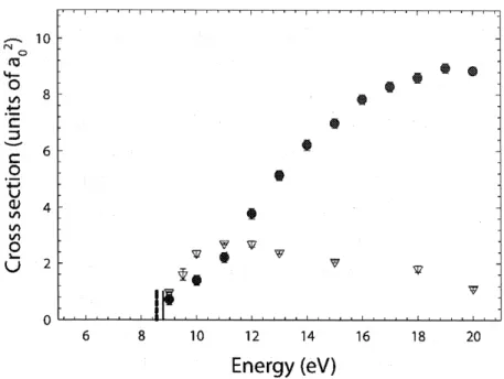
In 1997, Merrison et al. reported on the production of hydrogen using the charge conjugate reaction p + Ps → H + e+ [40]. In this experiment a proton beam with en-ergy in the range 11-16 keV collided with a slow positronium target. The free positrons resulting from this reaction were detected by an electron multiplier array and a scintil-lation detector (NaI) in coincidence. Heated thin silver foil was employed to produce ortho-positronium with about 3.1% efficiency. The protons were generated by a radio frequency hydrogen discharge reaction, and their current was measured by a Faraday cup. The number of registered coincidence events was 211 ± 46 and the measured cross sections were σH = 26(±9)×10−16cm2, 7.8(±2.3)×10−16cm2 and 7.6(±4.4)×10−16cm2
for proton impact energies of 11.3, 13.3 and 15.8 keV, respectively. Figure 2.2 shows the results of Merrisonet al. along with the predicted cross sections from three different models.
Unlike Merrison et al. who detected the positrons resulting from the reaction, the ANTION project intends to directly detect the (anti)hydrogen ions and atoms using microchannel plate detectors (see Chapter 4 for a description of this detector). The (anti)hydrogen ions and atoms will follow the same trajectory as the original antiproton beam. An electrostatic device will be used to separate the neutral particles from the charged particles.
Besides the number of (anti)atoms or ions produced in these reactions, it is crucial to know the time and spatial distributions of the ortho-positronium density inside the cavity, as well as those of the (anti)proton pulse. The density will be inferred by com-bining the information of scintillation detectors, which will monitor the decay of the positronium atoms, with a detailed GEANT4 [41] simulation of the positronium and proton distribution inside the cavity. At CERN, the detection system will be comple-mented with micromegas detectors [42] - a particle tracker, to detect the annihilation of the antiprotons in ¯H and ¯H+.
2.1. THE GBAR EXPERIMENT
Figure 2.2: Figure from [36] comparing the experimental results of Merrison et al. [40] (•) and three different cross section models of the H reaction for positronium in the ground state. In the case of the experimental data points no distinction is made between the hydrogen energy states. The cross sections were evaluated with the hydrogen excited up to the 5d state.
In the first phase of the ANTION project, the LINAC positron source at Saclay will be employed (see Chapter3for a description of this apparatus). Since this LINAC (4.3 MeV providing a flux of 3×10⁶e+/s) produces less energetic electrons than the one at CERN, the expected positronium density in the cavity is lower - of the order of 1010cm−3, assuming 108 positrons are accumulated. Therefore, only the hydrogen production cross section can be measured since a denser positronium cloud is needed for theH- reaction. Moreover, the positronium will be in the ground state. In a first approach, the goal is to try to reproduce Merrisonet al. results, i.e select the protons’ impact energies 11.3 keV, 13.3 keV and 15.8 keV; later one would like to validate the theoretical cross sections by scanning the impact energy. At CERN a similar study will be performed for the antimatter reactions, while for the GBAR experiment lower impact energies are preferred since the cross sections are higher, according to [37,43].
2.1.2
H
¯
+cooling and the ¯
g measurement
After being formed, the antihydrogen ions will be electrostatically separated from the antihydrogen atoms and from the antiprotons, and guided to a RF Paul trap, already inside the free fall vacuum vessel. There, the anti-ions will be sympathetically cooled to 10 mK by a Doppler-cooled crystal of 9Be+ and HD+, or H+2 ions, in millisecond time scales. Further cooling is still required, hence an individual ¯H+and a Be+ ion will be transported to another Paul trap, named precision trap. Here, they will be cooled by Raman side-band cooling [44], reaching 1 neV. A more detailed description can be found in [45]. The ¯H+ is now ready to lose the excess positron by photodetachment,
becoming neutral for the free fall measurement. The gravitational acceleration of ¯H, ¯g = m¯g
¯
mig, will be measured by determining the time interval between the photodetachment and the impact of ¯H on an annihilation plate after its free fall, ∆t. The photodetachment laser pulse defines the start time of the free fall, while the stop is defined by the detection of the pions that result from the annihilation of the antiprotons, once the ¯H hits the walls of the vacuum chamber.
The equation that describes the free-fall movement is: ∆z = 1
2g∆t¯ 2+ v
0,z∆t , (2.6)
where ∆z is the distance between the second Paul trap and the annihilation plate, which is known with precision, and v0,z the initial vertical velocity after photodetachment. The latter term presents the main source of uncertainty. Its origin is the energy of the ¯H atom, and from the recoil of the photodetached positron. At 1 neV, 1500 annihilations are necessary to achieve 1% precision on ¯g [15].
The ¯H annihilates into two 511 keV photons and, in 95% of the cases, the proton-antiproton annihilation produces a set of charged and neutral pions, with 99% of the latter decaying into two high energy gamma rays. The detection of the annihilation products requires both vertex position reconstruction, provided by a charged particle tracker, and accurate timing of the annihilation made possible by scintillator counters surrounding the tracker.
(a)
(b)
Figure 2.3: A preliminary drawing of the free fall chamber, Micromegas and time-of-flight detectors. (a) 18 50×50 cm2 Micromegas detectors are arranged in 6 triplets to cover all sides of the vessel. The ¯H+ ions enter the chamber from the side into the first Paul trap located in the interior. (b) 44 plastic scintillators and 88 PMTs compose the time-of-flight apparatus, providing a 0.2 ns resolution of the ¯p annihilation time and cosmic ray rejection.
2.2. GBAR CHALLENGES AND COMPETITION
The charged particle tracker will consist of a set of planar chambers that allow the measurement of both x and y coordinates with an accuracy of a few hundred microns. To achieve this, micro-mesh gaseous detectors (Multiplexed Resistive XY Micromegas) [42] of dimensions 50×50 cm2 with a pitch of 400 µm have been developed. In order to ensure a good tracking efficiency, each of the 6 faces surrounding the vacuum vessel will be equipped with 3 layers of chambers. This configuration will result in a spatial resolution of the order of 1.5 mm in the vertex reconstruction of the antihydrogen annihilation point. Four walls of scintillator arrays will surround the Micromegas tracker with the purpose of detecting charged tracks and some of the γ-rays from positron and antiproton annihilations, providing the time of the annihilation with a resolution smaller than 0.2 ns. They will also contribute to cosmic ray rejection, being able reduce the background fraction below 0.2%. A drawing of the free fall chamber can be seen in figure 2.3, as well as the tracking and time-of-flight detectors.
2.2
GBAR challenges and competition
Each step of the GBAR endeavor is a scientific achievement in itself. First of all, no other group has ever formed a plasma with 1010 positrons, with the present record being ∼ 4×10⁹, which took 4.5 hours to accumulate [46]. In fact, a buffer gas trap has never been used in combination with a LINAC. This thesis aims to prove that such a combination is indeed possible. Furthermore, the production and cross section measurement of the H− and Hbar+ reactions have never been executed before and are technically very challenging, namely the focusing of a positron and antiproton beam in a very small cavity with a section of 1 mm2, the extraction and acceleration of a 1010 particle beam from a 5 T magnetic field to a “zero” field region, and in particular the detection of the (anti)atoms and (anti)ions. The feasibility of capturing ¯H+ ions and cooling them to micro kelvin temperature still needs to be proved. Capturing the
¯
H+ ions with an energy of several keV and cooling them down to an energy of the order of 10−9eV, implies an energy reduction of 12 orders of magnitude. Nonethe-less, the results of simulations are promising suggesting the capture efficiency can be larger than 50%, if the anti-ions’ energy spread, ∆E, is smaller than 25 eV [45]. They also show that the ions can be sympathetically cooled in 10 ms for an initial kinetic energy of 18.5 meV (more than 400 K) [47]. Hilico and co-workers are in the process of sympathetic cooling H+2 or H+ ions with these technique with the goal of studying and optimizing this technique before applying it to anti-ions [45]. At last, ultra-high vacuum techniques need to be employed in the traps and in the free fall chamber, since these (anti)ions/atoms are rare and annihilate easily when in contact with any residual gas. Not less important, any stray magnetic fields need to be eliminated (shielding the free fall chamber with mu-metal for example) in order to not perturb the Raman side band cooling and the ¯g measurement.
Two other collaborations are attempting to measure the gravitational acceleration of ¯H, at CERN. Recently, the ALPHA collaboration reported a proof-of-concept ex-periment [48] that measured | ¯mg/ ¯mi| < 75 with a statistical significance of 5%. While
this measurement is significant in the sense that it was the first ¯g measurement, it does not allow to any conclusion specially regarding the sign of the gravitational force.
Moreover, the experimental setup used by ALPHA was not conceived with this mea-surement in mind, but to perform ¯H spectroscopy . For that reason, a new apparatus will be constructed, named ALPHA-g [49], to make this measurement with 1% accu-racy. This setup is a vertical adaptation of the ALPHA antihydrogen trap [50], in which cold (<500 mK) ¯H atoms are released in a controlled way to execute the free fall. A tracking vertex detector, a Time Projection Chamber (TPC) [51], pinpoints the position of the antiproton annihilation on the walls of the trap. ALPHA-g is par-ticularly well positioned to be the first experiment to achieve 1% accuracy, as all the required techniques to perform this measurement have already been demonstrated by the collaboration, in particular their expertise in trapping antihydrogen.
Another competitor is the AEgIS (Antimatter Experiment: Gravity, Interferometry, Spectroscopy) collaboration [52]. Their goal is to perform the gravity measurement by observing the vertical displacement of a ¯H beam with velocity in the range 400 m/s to 600 m/s, as it traverses a Moiré interferometer with two gratings. The antihydrogen beam eventually annihilates on an emulsion detector, that determines the position of the annihilation vertex with a spatial resolution of 1 µm [53]. The vertical shift is given by ∆y = F τ2/m, where F is the gravitational force, τ the time of flight between two interferometer gratings and m the ¯H mass. A shift of the order of 10 µm is expected. While ALPHA produces antihydrogen by mixing an antiproton plasma with a positron plasma in a Penning-type trap, AEgIS will produce the antihydrogen atoms using the charge exchange reaction Hbar, but with positronium excited to Rydberg states (high quantum number states). This not only increases the reaction cross section, as it scales with n4, but also allows the production of antihydrogen in Rydberg states which, due to their large dipole (scales with the square of the principal quantum number), allows the manipulation of the atoms using electric fields (using the Stark effect) and the production of an antihydrogen beam. The AEgIS collaboration have a head start in comparison to GBAR: they can routinely trap 108 positrons and excite positronium to Rydberg states. They are also able to trap antiprotons but have yet to produce an antihydrogen atom. While they have proven the feasibility of the free fall measurement using this technique with antiprotons with 106 keV mean energy [54], they still have a long road ahead to produce a ¯H beam with 500 m/s velocity, to obtain the desired 1% accuracy.
2.3. THESIS OUTLINE
2.3
Thesis outline
The main goal of this thesis is to develop some of the tools necessary for the hydrogen cross section measurement, in the framework of the GBAR collaboration. These tools include a buffer gas trap for the trapping and accumulation of positrons, and a Monte Carlo simulation of the time and spatial distribution of the positronium atoms in the reaction cavity. The remainder of this thesis is organized as follows:
• Part II is dedicated to positron production and accumulation in the buffer gas trap. In Chapter 3 the positron source and the beam line present at Saclay are described. Chapter 4 provides a few theoretical tools necessary to understand the physics of positron traps and an historical overview of the Penning trap, in which this trap is based on. In addition, this chapter includes a detailed description of the trap that was built during the course of this thesis. Chapter 5 presents the experimental work conducted to commission and optimize the trap. It describes trapping protocols and optimization procedures designed to increase the trap performance, as well as the study of the effect of the buffer and cooling gas and the application of the rotating wall technique.
• Part III presents a Monte Carlo simulation developed to evaluate the time and spatial evolution of the ortho-positronium atoms in the reaction cavity. An esti-mation of the number of hydrogen atoms produced as a function of the proton impact energy is given, according to the theoretically computed cross sections for hydrogen production. In addition, a suggestion is proposed to increase the number of positronium atoms in the cavity. Finally, the background signal that contaminates the ortho-positronium signal is evaluated.
• Part IV includes the study of a positron moderator - a material that emits slow positrons upon impact with a positron beam. Firstly, a brief introduction regarding the physics of positron moderation is given, followed by a description of the experimental setup employed in this study. The measurements of the work function and diffusion length of an epitaxially grown layer are reported, as well as the moderation efficiency. While being a small parallel project undertaken during this thesis, it is closely related to GBAR experiment as it can potentially increase the efficiency of positron trapping.
• Part V concludes this thesis by summarizing the achieved results and by pro-viding some suggestions for the future progress of the work described.
Part II
3
Positron source and transport
“Any sufficiently advanced technology is indistinguishable from magic.” Arthur C. ClarkeContents
3.1 Positron sources . . . . 21 3.2 The positron source at Saclay . . . . 22 3.3 Positron beam characterization . . . . 25
3.3.1 Electrons . . . 25
3.3.2 Positron beam parallel energy distribution . . . 27
This chapter describes the pulsed positron beam source at CEA Saclay, which was used in the experiments reported in this thesis. A brief summary of positron sources is firstly given, followed by a description of the positron source at Saclay, and concluding with the characterization of the positron beam.
3.1
Positron sources
There are two ways of producing positrons: β+decay and positron-electron pair produc-tion, when a γ-ray with energy greater than the energy of an electron and a positron, 1.022 MeV, interacts with the electric field of a surrounding atomic nucleus. Most positron experiments, and in particular table-top positron sources, use a β+ emitter as a positron source. In an isotope rich in protons, a proton is converted by weak interaction into a neutron, emitting a positron and a neutrino.
The22Na nuclide combines a relatively long half life of 2.6 years and a high positron yield of ∼ 90%. It is, therefore, the most common isotope used in positron experiments. It decays into an excited state of22Ne, which subsequently de-excites into the ground state emitting a 1275 keV γ-ray:
22Na →22Ne + β++ ν


![Figure 4.3: Diagram of Surko’s three stage positron accumulator [71]. Each stage corresponds to a set of electrodes with successively larger diameter, creating three distinct pressure regions](https://thumb-eu.123doks.com/thumbv2/123doknet/12721459.356672/58.892.233.687.473.796/diagram-positron-accumulator-corresponds-electrodes-successively-diameter-creating.webp)