Publisher’s version / Version de l'éditeur:
Canadian Geotechnical Journal, 15, 2, pp. 269-282, 1978-05
READ THESE TERMS AND CONDITIONS CAREFULLY BEFORE USING THIS WEBSITE.
https://nrc-publications.canada.ca/eng/copyright
Vous avez des questions? Nous pouvons vous aider. Pour communiquer directement avec un auteur, consultez la
première page de la revue dans laquelle son article a été publié afin de trouver ses coordonnées. Si vous n’arrivez pas à les repérer, communiquez avec nous à PublicationsArchive-ArchivesPublications@nrc-cnrc.gc.ca.
Questions? Contact the NRC Publications Archive team at
PublicationsArchive-ArchivesPublications@nrc-cnrc.gc.ca. If you wish to email the authors directly, please see the first page of the publication for their contact information.
NRC Publications Archive
Archives des publications du CNRC
This publication could be one of several versions: author’s original, accepted manuscript or the publisher’s version. / La version de cette publication peut être l’une des suivantes : la version prépublication de l’auteur, la version acceptée du manuscrit ou la version de l’éditeur.
Access and use of this website and the material on it are subject to the Terms and Conditions set forth at
Review of engineering behaviour of marine clays in eastern Canada
Penner, E.; Burn, K. N.
https://publications-cnrc.canada.ca/fra/droits
L’accès à ce site Web et l’utilisation de son contenu sont assujettis aux conditions présentées dans le site LISEZ CES CONDITIONS ATTENTIVEMENT AVANT D’UTILISER CE SITE WEB.
NRC Publications Record / Notice d'Archives des publications de CNRC:
https://nrc-publications.canada.ca/eng/view/object/?id=66cdafd7-4e5c-424a-8a1e-b7a40112aa77 https://publications-cnrc.canada.ca/fra/voir/objet/?id=66cdafd7-4e5c-424a-8a1e-b7a40112aa7732\
- 2
National Research
Conseil national
OCouncil Canada
de
recherches Canada
REVIEW OF ENGINEERING BEHAVIOUR OF MARINE
CLAYS
IN
EASTERN CANADA
by E. genner and K. N. Burn
Reprinted from
Canadian Geotechnical Journal Vol. 15, No. 2, May 1978 p. 269-282
DBR Paper No. 77 1
Division of Building Research
270 CAN. GEOTECH. J. VOL. 15, 1978
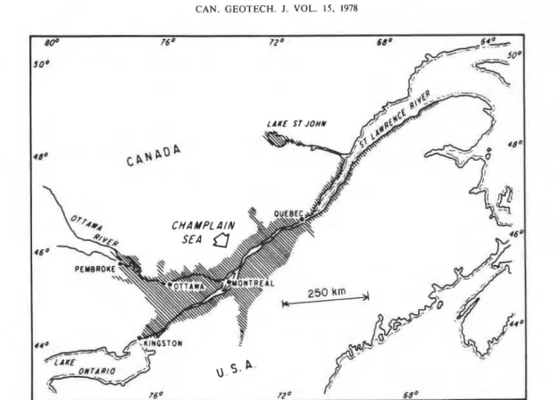
FIG. 1. The Champlain Sea (from Crawford (1968), reproduced with permission from Engineering Geology).
common usage referred to as Leda clay, although minerals found in the clay fraction are represented sometimes they consist almost completely of silt in the silt and sand size fractions. The major size particles or the proportion of silt is too large change accompanying particle size is an increase to be referred to as a clay. of phyllosilicates in the small-size fractions, with
These marine sediments are widespread through- consequent dilution of the other minerals.
out the Ottawa and St. Lawrence river valleys, Several mineralogists have drawn attention to reaching westward to the lower regions of Lake the existence of unstable primary minerals in the Ontario and extending northward into the Lake clay fractions signifying a youthful deposit. The St. John drainage basin in the province of Quebec minerals are almost certainly detrital, although (Fig. 1 ) . The deposits range from 10.7 to more chemical weathering or diagenesis may have con- than 61 m (35 to 200 ft) thick; dating studies tributed to the formation of some of the mixed- place their time of origin between 12 000 and 9000 layer and expanding-lattice clay minerals (Gillott years BP, based on from shell and peat sources 1970).
Mineralogy
Fabric, Structure and Sensitivity
The mineralogical composition of the marine clays may be summarized as follows (Brydon and Patry 1961 ; Gillott 1970) : Montmorillonite or other expanding layer silicates are absent, or present only in small quantities. Some chlorites anc! vermiculites are normally present. Mica, hydrous mica, or illite are the predominant clay minerals. Rock-forming minerals in varying pro- portions of feldspars, quartz and amphibole make up a large part of the clay size fraction, with feldspars predominating. The same rock-forming
The fabric of Leda clay consists of an assem- blage of silt, clay size rock fragments, and clay minerals in which the arrangement of clay platelets ranges from a completely random orientation (card house fabric) to a preferred orientation where the flat platelets are parallel to the bedding plane. The more normal orientation of clay platelets existing in the field is somewhere between the two extremes. Compressed anisotropically, the clay platelets tend to take on a preferred orientation normal to the direction of compression as the total void space is reduced. The change in fabric can be shown to
PENNER AND BURN 27 1
FIG. 2. Scanning electron micrographs of Leda clay from the Ottawa Sewage Plant from a depth of 16.2 m
and a preconsolidation load of 478 kPa (from Gillott (1970), reproduced with permission from Engineering
Geology).
be one of increasing, preferred particle alignment I normal to the direction in which the load is
i
applied. A preconsolidation load of 0.48 mPa was estimated for the sample shown in Fig. 2. The'
I scanning electron micrograph of the sample shows
I some particle orientation parallel to the bedding plane. The degree of orientation was considerable,
I based on X-ray diffractograms using both chlorite
i
and illite minerals (Gillott 1970). Penner ( 1963) also had studied preferred orientation in Leda clay, both by photographing the change in light1
reinforcement and interference during rotation of thin sections between crossed polaroids, and by anisotropic thermal conduction. Both methods gave the same results and were supported by Gillott's ( 1970) work.The open type of fabric was formed during sedimentation in saline water of various levels of electrolyte concentration, i.e. marine or brackish water. It represents the type of fabric formed under
I
conditions of flocculation where adjacent particles tend to aggregate during sedimentation because repulsion forces are low and they are brought into close proximity by their thermal energy. As the cations are partly polarized van der Waals forces of attraction take over. Subsequent consolidation by the physical weight of the sediment above brings the points of contact and the particles generally into still closer proximity.The clay fabric develops structural strength in this way because of the forces of attraction and weight of the deposit above. In some cases it is said that the strength has been augmented further by the deposition of cementing materials such as iron oxides or carbonates around the points of
contact between particles. Bjerrum (1973) has in- dicated that cementing is not confined to the points of contact alone but is smeared over the entire surface of the particle.
All conditions required to produce a soil of high sensitivity1 are now present. The forces of repulsion increase between particles when the electrolyte concentration is reduced in the pore water. This might occur during leaching of the clay with fresh water. Although the fabric remains intact, the structural resistance to stress and de- formation is greatly diminished. Any physical dis- turbance of the structure causes the water to be released from the pores of the open fabric as con- tacts or bonds are broken down and the entire mass may become a viscous fluid.
This description, somewhat oversimplified here, is known as the leaching theory (Rosenqvist 1953). It is, however, only one means by which sensitivity may develop. Soderbloom (1960) per- formed experiments that led him to believe that oxidation plus infiltration of organic dispersing agents from peat beds might well account for in- creased sensitivity. Some freshwater deposits are also known to be quite sensitive.
Skempton and Northey (1952) have proposed a sensitivity classification that was modified subse- quently by Rosenqvist (1955) (see Table 1 )
.
The measured sensitivity, however, may depend on the equipment or apparatus used and on test procedure (see, for example, Eden and Kubota (1961)). There are, therefore, two features that characterize the unusual behaviour of Leda clay as it is found'Sensitivity is the ratio of natural strength to remoulded strength.
272 CAN. GEOTECH. J. VOL. 15, 1978
TABLE 1. Classification of sensitivity
Range Description
Insensitive
Clays of low sensitivity Clays of medium sensitivity Sensitive clays
Slightly quick clays Medium quick clays Very quick clays Extra quick clays
today: ( 1 ) the possibility of excessively large settlements arising out of the open nature of the fabric, and (2) the possibility of a substantial loss of strength that cannot be recovered through thixotropic processes resulting from the breakdown of the structure.
Sensitivity and Electrokinetic Phenomena Early work (Bjerrum 1954) on Norwegian marine clays showed a distinct inverse relation between clay sensitivity and the electrolyte content of pore water, which contrasts sharply with that of Leda clay. Figure 3 gives a plot of laboratory- measured sensitivity as a function of specific con- ductivity of pore water (Penner 1965). Table 2 gives the relation between the electrokinetic po- tential El,, a measure of interparticle repulsion, and sensitivity. Soils with a low surface area (silty) tend, however, to be more sensitive for the same electrokinetic potential than soils with a moderately high surface area. It is clear that the degree of sensitivity of a soil is not uniquely dependent on any one factor; indeed sensitivity is an expression of many interrelated soil properties and the inter- play of environmental factors. The electrokinetic potential, like sensitivity, is an expression of the present condition of the surface forces and be- comes a powerful tool in studying the influence of various factors, e.g. salt content of the pore water. One significant factor that emerges is the in- fluence of mono and divalent cations on sensitivity. Table 2 shows that increases in the percentage of monovalent cations over divalent cations in the pore water varies directly with increases in sensi- tivity. An approximate value for salt concentration
( g / L ) in the pore water may be calculated by dividing the specific conductivity by the factor
1.52 x
Major Engineering Problems
There is currently a resurgence of research activity and renewed interest in the more important soil engineering problems in Leda clays. Increased
9
.
.
t l l l l l l l l l l
1 2 3 4 5 6 7 8 9 10 11 12 13 14 1 5 1 6 S p e c i t ~ c C o n d u c t i v i t y . ASxlC13 , o h m - ' c m - '
FIG. 3. Salt concentration of the pore water in terms of
specific conductivity as a function of sensitivity (from
Penner (1965), reproduced with permission from Canadian
Journal of Earth Sciences).
I
construction activity has afforded greater oppor- tunity to carry out field and laboratory research, and such studies have been supported generously by government grants to universities and industry. Attention is drawn mainly to the more recent and significant study areas illustrating the problems the authors consider to be of paramount importance. Much significant work, however, is still under way and is not available in the open literature for review.
Slope Stability and Flow Slides
It is highly significant that the sensitivity of Leda clay below the fissured drying crust is rarely less than 10 and sometimes reaches several thousand. The strength of the remoulded material at high sensitivities is often so low that measurements are not very precise. It is not surprising, therefore, that this vast deposit is scarred by characteristic flow slide features similar to those of the Scandinavian countries. Many flow slides occur each year, often with disastrous results. Examples of both old and new slides that took place on opposite sides of the South Nation River in Ontario are shown in Fig. 4, one only 2 years ago, the other, about 65 years ago (Eden et al. 197 1 )
.
PENNER AND BURN 273
TABLE 2. Electrokinetic potentials for soils listed in order of sensitivity*
Surface Specific
Soil Depth E k MC Clay area cond. Ca+ +
+
Mg+ + N a + + K +code No.? (m) PI (mV) S (%) (%) (m2/g) A(x lo3) (%) (%)
136-2 9 . 8 44 1 2 . 6 11 7 5 . 3 85 77.8 1
-
-
94-13-3 6 . 7 38 1 6 . 2 30 66.9 82 72 1.07 47 5 3 124-19-5 18.3 17 2 0 . 2 3 3 62.9 77 62 1 . 7 8 13 87 126-5-4 2 2 . 9 45 16.1 34 6 2 . 4 85 72 15.4 11 89 126-4-4 19.8 45 1 6 . 4 45 65.3 89 - 14.6 10 90 126-1-4 1 0 . 7 40 1 9 . 3 53 66.1 78 60 5.61 9 9 1 126-3-4 1 6 . 8 46 17.4 60 6 3 . 9 79 66 11.4 10 90 126-2-4 13.7 38 21 .O 74 6 3 . 8 78 60 8.97 9 91 129-16-4 1 7 . 4-
2 2 . 2 118 80.1 85 85 2 . 7 1 --
124-3-5 3 . 7 28 2 4 . 9 126 8 6 . 6 71 79 2 . 2 5 7 93 129-7-5 9 . 1 32 19.9 183 8 9 . 7 79 76 1 . 0 2 8 92 124-12-5 1 1 . 9 27 28.8 453 8 3 . 5 76 79 2 . 1 9 5 95 94-20-5 1 6 . 2 8 23.5 575 52.5 72 47 2 . 9 4 8 92 124-9-6 9 . 1 24 2 9 . 7 600 9 4 . 0 86 80 2 . 3 3 5 95 94-27-1 22.0 10 21.4 900 5 0 . 6 67 54 3.54 6 - 94 123-2-3 5 33.8 > l o 0 0 41 .O 54 29 0 . 6 2 98*From Penner (19651, reproduced with permission from Canadian Journal o f Earth Sciences.
tlocations: 94, sewer plant; 123, Toulnustouc; 124, Gloucester; 126, Queensway Overpass; 129, Breckenridge, P.Q.; 136, interceptor shaft.
A typical flow slide may be readily identified by applies to the stability of slopes (Eden and Mitchell
its characteristic features. Figure 5 is a schematic 1970). It is possible, using information obtained
drawing showing a section and perspective taken in the course of a normal site investigation, to from a recent paper by Mitchell and Markell evaluate the susceptibility of a given site to slope
!
(1974). The most characteristic features are the failure and make a reasonable prediction of thei
overspill apron, normally consisting of liquefied extent of a potential earth flow according to soil, lumps of unremoulded surface material and Mitchell and Markell (1974).other vegetative debris, the shape of the crater, In the latter study, slope profiles were established
and the spoil ridges and pinnacles if not destroyed adjacent to identified landslides, using topographic
or removed by erosion. Figure 4 does not s h w the maps, a stereo plotter and, in some cases, field
apron because the spoil flowed into the river. When surveys. In this way the value for H, the height of
flow slides occur on river terraces not inundated in the slope, was obtained. To gather information on
water, however, the apron is plainly evident and soil profile, soil classification and strength data
appears as a tongue of largely remoulded soil from site investigation were used wherever avail-
rivalling and sometimes exceeding in area the ex- able. Most of the values for undrained strength C,,
tent of the crater (Crawford 1961). and sensitivity were from field vane measurements,
Features of old flow slides are easily identified but where such information was not available soil
on air photos. There are literally thousands of sampling and field vane tests were carried out.
small flow slide scars throughout the marine clay Mitchell and Markell (1974) showed, for some 40
region, along terraces, small creeks and streams slides, that y H CII where y is the bulk density
and the banks of major rivers. A study by Mitchell ( H and C,, are defined above). They showed,
and Markell (1974) showed that hundreds of further, that the amount by which y H exceeded
flow slides of over 1 ha in area have occurred 6CIl correlated with the distance of retrogression,
throughout Champlain Sea deposits in the provinces i.e. the distance from the mouth of the crater to
of Ontario and Quebec. Fifty of the larger ones the backscarp (Fig. 5 ) . It appears therefore that a
were responsible for a total loss of life of over method is at hand for evaluating the potential
100; and 40 000 ha of upland were destroyed in danger associated with acres of flow slides and for
the process. measuring their magnitude.
Two recent papers account for some improve- The recent contribution of Eden and Mitchell
ment in the understanding of the flow slide ( 1970) involved determination of strength param-
mechanism. The mode of failure from laboratory eters under low effective normal stresses. Under
studies of drained shear strength under low ef- these conditions the clay exhibited dilatant be-
fective normal stress has resulted in a new appre- haviour and a predominantly frictional shearing
274 CAN. GEOTECH. J. VOL. 15, 1978
FIG. 4. Flow slides on the South Nati~
the development of discontinuities on pre-existing planes of weakness and resulted in shearing of the clay into small blocks from 1 to 10 mm across. The frictional strength parameters were supported by field observations of the failure surface and the critical role of groundwater in slope instabilities. It was further shown that many slip surfaces develop simultaneously, so that an extensive zone of soil is considered to deform at the time of failure.
Shrinkage and Damage to Buildings
The collapse of the flocculated, open fabric that characterizes Leda clay, together with its very low content of swelling clay minerals, means that shrinkage is essentially irreversible. Differential shrinkage, either as the result of soil variability or the removal of water from one side of the founda- tion, can induce serious racking in both the foundation and the superstructure. Trees are a primary cause of shrinkage, occurring most notably in unusually dry summers. Shallow foundations used to support small structures and domestic dwellings are most often affected.
Figure 6 shows the ground movements induced
by water removal by a row of elm trees. The de-
formations indicate the distance by which founda-
on River, Ontario (RCAF air photo).
FIG. 5. Typical features of earthflows (from Mitchell and Markell (1974), reproduced with permission from Canadian Geotechnical Journal).
tions and trees should be separated if damage is to be avoided on this type of soil. Most of the trouble occurs during unusually dry seasons. When rainfall is low in summer the trees reduce the moisture content of the surrounding soil, inducing serious shrinking problems. Supplementing low rainfall by watering is not effective normally be- cause it is impractical to supply water in sufficient quantities. Small trees or those that do not transpire excessively should be selected for new plantings. Heavy transpiration rates usually associated with
PENNER A N D BURN
DISTANCE FROM TREES
-
12
-
-
14
-
FIG. 6. Variation in maximum vertical ground movements in Leda clay near elm trees in 1955 (from Bozozuk
( 1962), reproduced with permission from Engineering Journal).
fast growing trees such as Lombardy populars are to be avoided.
Studies carried out by Bozozuk ( 1962) in an
area covering 36 city blocks in central Ottawa show the extent of existing damage and how it was specifically related to the proximity of trees to domestic dwellings. Recommendations now used for the prevention of such damage to shallow- founded structures by shrinkage in Leda clay from water removal by tree roots is based on extensive work carried out by Bozozuk and Burn (1960) and Bozozuk (1962). The more fundamental aspect of shrinkage and rewetting characteristics
is described by Warkentin and Bozozuk (1961 );
and Burn (1973) has shown the rapidity with which shrinking is induced and the fact that severe damage is not confined to old houses.
Frost Heave and Uplift by Adfreezing
The relatively high water content of Leda clay, I
its high permeability and silty nature make these
'
soils highly susceptible to frost heaving. The highpermeability of the surface soil is related to its fissured nature. Water for frost heaving is readily available because a high water table exists at the beginning of most winters.
During an average winter in the Ottawa region the frost heave in snow-cleared areas is from 75
to 100 mm, attributable mainly to ice lens forma- tion at the freezing front. Major highways are de- signed to avoid the heaving problem, but where design techniques have proved inadequate artificial insulation may be used (Penner 1966, 1968). On secondary roads differential heaving seriously re- duces the riding quality and loss of subgrade strength results in rutting when the ice melts unless traffic restrictions are imposed.
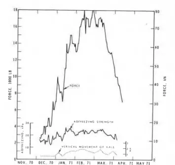
The heaving pressure generated when displace- ment is resisted can be very high. Figure 7 gives the force developed over one winter period on a 305 mm diameter plate placed on the ground surface. Measurements of force between a rigid reaction frame anchored to rock and the surface plate show a force of 133 kN at the peak of the heaving season (Penner 1970a).
Foundation walls to which soil is allowed to freeze, as often happens in unheated buildings, can be displaced vertically (or in the direction of heat flow) by heaving forces as ice lenses develop. Such movements result when displacement due to ice lens growth in the soil is transmitted to the foundation wall by adfreezing forces; displacement may be even more serious if the frost line is allowed to penetrate below the footings of the foundation. This, however, is normally avoided by placing the footing below maximum frost depth. Displacement by adfreezing must be prevented by
C A N . GEOTECH. J. VOL. 15. 1978
d I20
1 11 1~ 1 11 11 ~ 11 11 1, 1 11 1 , , 11 . 11 ~ 11 ~,
I b l FORCE AND AVERPGE STRESS
+
4 ON I ' D I P CIRCULAR SURFACE PLATE 140
NOV 68 DEC 68 JAN 69 F E B 69 M A R 6 9 APR 69
FIG. 7. Temperature, force and frost depth results on Leda clay (from Penner (1970a), reproduced with per- mission from Canadian Geotechnical Journal).
suitable design measures, including backfilling with nonfrost-susceptible material and drainage.
Figure 8 gives the force, adfreeze strength
(Penner 1974) and small strain involved because of stiffness in the reaction frame. Such forces can be avoided by proper design, based on preventing adfreezing by the use of insulation or by replacing frost-susceptible soil with non-frost-heaving gran- ular materials. For heated buildings the basement space temperature is normally sufficiently high to prevent adfreezing of the soil to the foundation wall. Backfilling around the foundation with gravel is also effective; this combined with good drainage
V I l i i l C l l M O V I M t N l OP Y . A l l
4 ,. ... ,, ,-- . . . . -; .,,,
... .. .: , . - ,- '\
N O V . 70 DEC, 70 JAN. 7 1 F E E 7 1 M A R . 71 APR 7 1 M A Y 7 1
'
FIG. 8. Force measurements, calculated adfreeze strengths and vertical movement of block wall during heaving period 1970-1971 (from Penner (1974), repro- duced with permission from Canadian Geotechnical Journal).
at the footing level prevents any problem involving freezing even if the inside of the foundation walls are heavily insulated for reasons of heat con- servation.
Thermal Conductivity o f Leda Clay
Study of engineering problems that can arise when subgrade soils freeze below roads, streets and around the foundations of structures has led to the development of numerical methods for pre- dicting heat flow and depth of frost penetration. To carry out such predictions, values for thermal conductivity of the soil are required and this has led to the development of techniques to measure this parameter. A laboratory method that appears reasonably satisfactory is based on transient heat flow, using a line heat source. In recent thermal conductivity studies of Leda clay (Penner 1970b) a 229 mm long, 0.5 mm diameter steel probe was used. From the phase composition given in Fig. 9 and the results of measurements using this apparatus, values of thermal conductivity were determined as given in Fig. 10. The thermal con- ductivity of frozen Leda clay rises rapidly as the freezing temperature is lowered because the thermal conductivity of ice is about four times that of water. Because Leda clays in the field have high moisture contents this factor becomes very im- portant in carrying out heat flow calculations
PENNER AND BURN 277
FIG. 9. Phase composition as a function of temperature for undisturbed Leda clay samples (from Penner (1970b), reproduced with permission from Canadian Journal of
1
Earth Sciences).FIG. 10. Estimated and measured thermal conductivity of partially frozen soil (from Penner (1970b), reproduced with permission from Canadian Journal of Earth Sciences).
Undisturbed Field Sampling and Storage A basic premise underlying laboratory testing of soil is that the condition of the samule in the laboratory can be made to simulate the'field con- dition, so that in all respects its behaviour will represent that of in-place soil. At present there is no way in which soils can be sampled and placed in a testing apparatus without some change or disturbance occurring because of stress release and handling. Sensitive clays such as Leda clay are particularly susceptible to sample disturbance owing to the very nature of the soil fabric. There is, of course, quite a range of strengths within the Champlain Sea deposit, depending on location and depth. The 'brittle' deposits usually have a very high sensitivity and are thought to be most easily disturbed during the sampling process. They are normally considered to have 'cemented bonds', although the existence of cementation has not been shown except by indirect evidence. Soil samplers disturb the soil primarily because an extra volume of material, usually in the form of a thin-walled sampling tube, is introduced into the soil in re- trieving the sample. Depending on the design of the sampler the disturbance will vary, the least
occurring when it is possible to trim sample blocks of soil from the bottom of an excavation.
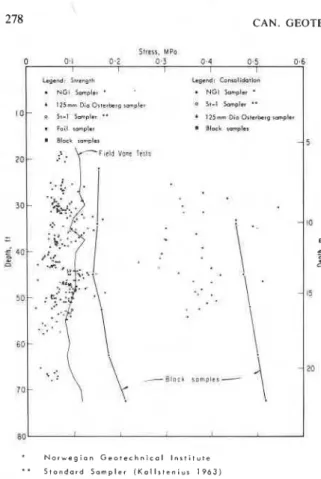
An opportunity to compare the results from test specimens obtained with a number of different samplers and from block samples arose during excavation to 21.3 m for pump wells at a sewage treatment plant near Ottawa. Shear strengths were also compared with those obtained with a field vane apparatus (Eden 197 1 )
.
Details of the four types of tube sampler may be found in the literature. All are standard samplers used in marine clays in Canada and Scandinavia. The plotted results (Fig. 1 1 ) of preconsolidation pressure and undrained shear strength show the poor relative quality of samples taken with tubes compared with block samples. The author states that only four of the 35 preconsolidation test re- sults were equal to or greater than those from the blocks; only 6 of 240 undrained strength tests were equal to or greater than the block tests. The laboratory test results indicated that values ob- tained from tube samples were only half as large as those obtained from samples taken from hand-trimmed blocks. Similarly, undrained shear strengths from the field vane over the entire depth were also lower. Eden (1971 ) concluded that "the sampling of sensitive clays can lead to extensive disturbance and must be considered seriously in any geotechnical investigation".
Comparisons have also been made by Bozozuk (1971) at a different site and on a softer Leda clay deposit to a depth of 6.1 m using samplers of two different sizes. He concluded that large- diameter tube samplers provide better quality samples than small ones, but there was no oppor- tunity to compare tube sample results with those from large, hand-trimmed block samples because there was no deep excavation. Bozozuk (1971 )
also evaluated the effect of storage on the measured preconsolidation pressure of a block sample. He was able to show that after 17 months of storage in a constant-temperature ( 12.g°C), high relative humidity (90-100% ) chamber, the measured pre- consolidation pressure was reduced by 5 % . He concluded that consolidation tests should be per- formed soon after sampling, although the decrease was not considered to be very important.
Settlement
The Geotechnical Section of the Division of Building Research, National Research Council of Canada, has, over the years, measured consolida- tion settlements resulting from various kinds of loads, including highway embankments for bridge
278 C A N . GEOTECH. J. VOL. 15, 1978
.
• S t a n d a r d Sampler ( K a l l r t e n i u r 1 9 6 3 )FIG. 11. Comparison of test results obtained on various
sampler types (from Eden ( 1 9 7 1 ) , reproduced with per-
mission from American Society for Testing and Materials).
approaches and mat foundations for apartment blocks. The predicted and, hence, the design settle- ments were based on laboratory testing, interpreta- tion and stress analysis and have not been very accurate with respect to either rate of settlement or total settlement. Although predictions of total settlements have generally been better than those for rates, the fabric and structure of Leda clay imparts to the soil unusual compressibility charac- teristics. It has been shown repeatedly that the usual approach to field settlement predictions (from laboratory tests as a model of field be- haviour and the classical theory of consolidation for the test interpretation) has severe limitations with this type of soil. Despite the disparities, laboratory consolidation determinations are still being used. The test procedure, including the rate of load application and interpretation of results, has been intensively investigated and there have been sub- stantial improvements (Hamilton and Crawford 1959; Crawford 1964).
A major factor in the prediction of settlement hinges on an understanding of both types that occur. During 'primary consolidation', settlement
is controlled by the permeability of the soil and the escape of pore water under pressure. When the pore-water pressure gradient has dissipated, settle- ment continues at a much slower rate that is normally referred to as 'secondary consolidation'. The phenomenon of secondary consolidation in Leda clay also appears to occur below the precon- solidation stress when no primary consolidation is involved and in practice accounts for fairly large settlements. In recent years research activity has moved towards interpretation of the observed time-settlement behaviour in terms of other than classical concepts.
In a recent study of the records of settlement of a single-storey building Crawford and Burn ( 1976) showed that considerable settlement occurs under constant effective stress conditions in the vicinity of preconsolidation stress, although the total stress on the soil is somewhat higher. 'Primary' consolidation, in which pore-water pres- sures were high, was over in 2-3 years, but low excess pore-water pressures, attributed to the slow breakdown of the clay structure, continued at a rate balanced by drainage.
Earlier, Eden (1961) suggested a number of reasons for the disparity between measured settle- ment in the field and settlement predictions based on laboratory test and consolidation theory. The first, and a major factor, is the sensitivity of the clay structure to disturbance and the effects of sampling (Eden 1971). The second is that the shape of the laboratory load-deflection curve, which is typical of especially sensitive clays (Terzaghi and Peck 1948), makes it difficult to determine accurately either preconsolidation stress or appropriate parameters for the rate and mag- nitude of primary compression. The third is that highly compressible layers of Leda clay are fre- quently overlain by a stiff crust. This makes it difficult to assess the distribution and intensity of the stresses in the soft layers below.
Jarrett (1967) has pointed out also that the generally accepted Terzaghi theory assumes that the only retarding mechanism of compression is the dissipation of pore-water pressure and totally ignores the importance of structure-time effects. In reviewing the work of Crawford ( 1964, 1965) and the interpretation of the consolidation test, Jarrett suggested that in a slow laboratory test (although conducted at a rate about 2000 times faster than that in the field) much of the consolidation taking place might normally be classed as "secondary".
Eden and Poorooshasb (1968) and Jarrett (1967) agree that there are three phases in the
PENNER AND BURN 279
TABLE 3. Settlement of compressible layers after 15 years Compressible layer
Total Thick- Compres- Average effective stresses in layer* Stress ratios
Location Soil settle- ness sion (kg/cm2)
(Ottawa depth ment AP ~r
area) (m) (an) (m) (cm) % P o PC AP Pr
--
P C - P o PC Apartment buildings 15 1.7 9 . 0 I .7 0.19 Green Creek 37 13.3 15.0 7 . 5 0.50 Main Street 27 16.2 7.3 7.7 1.06 Gloucester 20 27.4 3.7 21.9 6.00 Kars 15 64.0 6 . 0 40.1 6.70*NOTE: po = i11 sifu effective stress; p, = preconsolidalion stress; Ap = !
SlCCSS.
consolidation of Leda clay. Phase 1 is the elastic deformation range up to. the preconsolidation pressure; phase 2 is a stage of fabric breakdown by a form of structural viscosity beyond the pre- consolidation stress; and phase 3 is a classical process of primary consolidation with a definite relation between pressure and void ratio. Burn and Hamilton (1968), who studied loading of the soil below the preconsolidation stress, pointed out that structural breakdown in the clay also occurs where the soil is loaded below the preconsolidation stress. Settlements of significant magnitude con- tinue long after loads are applied and therefore cannot be classified as 'elastic'.
Eden and Poorooshasb ( 1968) suggested that the
second phase accounts for a significant part of the settlement observed at one of the sites they studied, and for the uniform but low pore-water pressures persisting throughout the soft compressible layer. A more cogent argument in support of the con- cept of continuing structural breakdown is that at one site where there was considerable increase in
density following a 7% compression of the clay
layer, no increase in shear strength could be de- tected with the field vane apparatus.
Load settlements in the field are complex and predictions are fraught with difficulties, primarily because of the sensitive nature of the clay soil and its slow structural breakdown when subjected to load increases. Significant settlements may occur when stress increases are either above or below the preconsolidation stress. Table 3 summarizes settle- ments of compressible layers at various sites after 15 years of observations. Stress ratios less than 1.00 indicate loads below the preconsolidation stress. (This information updates that given by
Crawford (1968) after 7 years of observation.)
Although predictions of settlements where sen- sitive clay deposits are loaded are not as accurate
0.70 2.40 0.60 1.30 0.35 0.54 0.70 3.20 1.10 1.80 0.44 0.56 0.50 2.70 1.22 1.72 0.55 0.64 0.43 0.62 0.32 0.75 1.68 1.20 0.65 1.40 1.50 2.15 2.00 1.54 -
itress increase due t o applied load; p , = in siru stress plus applied stress = final
as may be desired, there has been considerable advance in the understanding of soil behaviour: improvements in techniques for sampling sensitive soils; improvements in laboratory testing proce- dures that better simulate field conditions; and better understanding of the structure of the clay and its time-dependent characteristics.
Pile Loads by Negative Skin Friction
Piles located in deposits subjected to settlement carry down-drag or negative skin friction loads. Again, this is particularly important in Leda clay because of its high compressibility. The designer needs to know the magnitude of such loads in addition to those imposed by the structure.
The performance of both the end-bearing piles
( B O Z O Z U ~ and Labrecque 1969) and the free-
floating pile (Bozozuk 1972) has been described in detail. The instrumentation used to assess load- ing of piles by settlement was described earlier by Crawford (1969) and a useful resume of the field results was given by Bozozuk (1970).
End-bearing piles were installed to support an overpass structure of 4450 kN where the Leda clay deposit is some 82 m thick. The 48.8 m free- floating test pile was located on the centre line of a 9.1 m high bridge embankment. End-bearing
composite piles 91.4 mm in diameter, 82.3 m long
and of 12.7 mm wall thickness were filled with rein- forced concrete and subjected to down-drag loads while the embankment included settlements in the clay. During the first 5 years the clay deposit settled 2.1 m, of which 0.46 m occurred after pile installa- tion. In the first 3 years the negative skin friction load on each pile reached 7500 kN or 70% of the design value. During the same period the negative skin friction load on the floating steel tube pile, 305 mm in diameter and of 6.35 mm wall thick- ness, reached 1200 kN.
280 CAN. GEOTECH. J. VOL. 15. 1978 A X I A L L O A D I N P I L E . I O N S 5011 0 40 8 0 120 160 200 SAND EMBANKMENT A, ORGANIC B. SILTY SAND C. SILTY CLAY D. FINE SAND. STRATIFIED S I L I I STRATIPIED o - CLAYEY SILT : I00
-
..
120 - F SILTY C U Y 140-
110 - I I I I I I t I I 0 0 4 0 8 1.2 I 6 A X I A L L O A D I N P I L E , M NFIG. 12. Variation of skin friction load on 12-in. (305
rnm) diameter steel pile with time (from Bozozuk (1972),
reproduced with permission from Canadian Geotechnical Journal).
Bozozuk (1972) has shown that skin friction loads are related to horizontal effective stress act- ing on the skin. The predicted and observed loads on the free-floating pile compared favourably with respect to both neutral point and magnitude of load. Figure 12 gives comparisons at various times following pile installation.
Summary and Concluding Remarks
Geology, Mineralogy and Physico-chemical Behaviour
The Champlain Sea deposits are of post-glacial origin and cover extensive areas in the St. Lawrence and Ottawa river valleys, important for their heavy industrialization and dense population. That micas and illites are the predominant clay minerals has been verified. Feldspars, quartz and amphiboles in that quantitative order make up a large part of the clay size fraction.
The fabric of the deposit consists of a randomly oriented assemblage of clay minerals interspersed with 'rock flour'. A high moisture content is charac- teristic of this open geometric configuration, which reduces to a viscous slurry on collapse of the very sensitive materials. Major engineering problems such as flow slides and massive settlements, among others, are the direct consequence of an initially high moisture content that leads to structural collapse.
Sensitivity is a property closely identified with flocculated marine clays that have undergone
post-depositional leaching. It has been shown to correlate directly with measured electro-kinetic potential ( E k ) , but not with pore water salt con- tent. Below approximately 3 g of salt per litre of pore water, sensitivity is variable but high; above this, it is constant and relatively low. The physical properties that account for the engineering be- haviour of Leda clay generally parallel those of the Scandinavian marine clays.
The cause of brittleness is still controversial, although it is normally attributed to interparticle cementation. That, however, remains to be proved as far as Leda clays are concerned. In a general way the basis for the unusual behaviour of these sensitive clays is understood in physico-chemical terms, but solutions to engineering problems in Leda clay have not advanced as rapidly. None- theless, a good design capability now exists in Canada.
Major Engineering Problems
Flow slide scars are extensive along terraces, streams and riverbanks throughout the Leda clay deposit. More are added each year. Most recent studies indicate that hazardous slopes can be identified from the ratio of y H / C , , , soil sensitivity, and ground and surface water conditions, partic- ularly in the spring of the year. Warning systems are being studied as a temporary measure, but to protect both life and property stabilization tech- niques are needed. At present, both the identifica- tion of hazardous slopes and designs for their stabilization have not reached a satisfactory level, although work on these problems is continuing.
Damage to buildings from settlements around foundations can often be traced to the removal of water by trees. This type of damage is well under- stood and unnecessary settlements are accentuated during dry periods, but with proper landscaping techniques such problems can be avoided. Salient aspects of damage to foundations by trees include the following: ( 1 ) Consumption of water is pro- portional to the size of tree. ( 2 ) Fast-growing trees require copious amounts of water. ( 3 ) During landscaping it should be remembered that the distance between tree and building should be about the same as the height of the mature tree. ( 4 ) Rows of trees are especially aggressive with respect to water consumption and extend their influence further than individual trees. ( 5 ) As soon as settlement damage is observed any offending trees should be removed.
Leda clays are generally highly frost susceptible owing to their silty texture. In most regions the
PENNER A N D BURN 281
water table rises to the surface prior to the onset of winter. The two damaging aspects of frost action are frost heaving and loss of strength when thaw- ing occurs. Frost damage to roads is generally avoided by replacing frost susceptible materials with granular fill or preventing freezing by the use of thermal insulation. In heated structures frost damage is rarely a problem, but for unheated struc- tures preventive measures are much the same as for roads. In general, attempts to resist frost heave forces by loading are not considered a viable engineering solution because of their magnitude. In the more heavily textured deposits uplift pres- sures of 1.9 MPa have been measured. When calculating thermal patterns under roads and around buildings it must be remembered that thermal conductivity of ice is four times greater than that of water. This is of particular significance in high water content deposits such as Leda clay.
It is believed that in tube sampling of brittle soils particularly, serious disturbance can occur as a result of lateral strain. Of necessity, samplers must have a clearance ratio to reduce friction when the sample moves inside the tube during the
I
sampling process. Eden ( 197 1 ) has concluded that "at the present time
.
. .
large undisturbed block samples are the only ones that can be relied upon consistently". Comparison of laboratory tests of specimens from so-called 'undisturbed' tube samples and block samples indicate that the latterI have twice the undrained strength. Sample dis-
turbance has caused much concern, and greater emphasis has recently been placed on perfecting in situ measuring equipment and techniques.
Sample storage has also been investigated, but with proper facilities (constant temperature T and high relative humidities) its influence has been shown to reduce the original measured values by
. only 5 % after 17 months of storage.
With regard to settlement in Leda clay from various sources such as embankments, bridge ap- proaches, mat foundations, etc., the structural breakdown of the soil has been observed in terms of the resulting compression. The actual mech- anism of volume compliance on a microscopic scale and the roles played by permeability and pore pressures both below and above preconsolida- tisn pressures are not well understood. Part of the difficulty of attempting to draw conclusions or derive empirical relations between observations of
this direction. If much improved methods of sampling are developed or more reliable results are obtained with in situ methods this could change. The time settlement relations of laboratory tests to actual field load conditions must, however, be better understood in a quantitative sense before predictions of settlement with time can be more realistic.
Skin friction loads on a floating test pile in marine clay have been shown to be related to the effective horizontal pressures acting on the pile. The predicted friction loads compared favourably with measured loads with respect to both location on the pile and magnitude.
Acknowledgement
The authors gratefully acknowledge the per- mission of the authors and the journals involved for the use of the figures. This paper is a contribu- tion from the Division of Building Research, National Research Council of Canada, and is published with the approval of the Director of the Division.
BJERRUM L. 1954. Geotechnical properties of Norwegian marine clays. Geotechnique, 4(2), pp. 49-69.
1973. Problems of soil mechanics and construction on soft clays. Proceedings, 8th International Conference on Soil Mechanics and Foundation Engineering, Moscow, Vol. 3, pp. 111-159.
B o z o z u ~ , M. 1962. Soil shrinkage damages shallow founda- tions at Ottawa, Canada. Engineering Journal, 45(7), pp. 33-37.
1970. Field observations of negative skin friction loads on long piles in marine clays. Proceedings, Conference on Design and Installation of Pile Foundations and Cellular Structures, Lehigh University, Bethlehem, PA. Envo Pub- IishingCo., Inc., pp. 273-279.
1971. Effect of sampling, size and storage on test results for marine clay. American Society for Testing and Materials. Special Technical Publication 483, pp. 121-13 I.
1972. Downdrag measurements on a 160-ft floating pipe test pile in marine clay. Canadian Geotechnical Journal, 9, pp. 127-136.
B o z o z u ~ , M., and BURN, K. N. 1960. Vertical ground move- ments near elm trees. Geotechnique, 10(1), pp. 19-32. B o z o z u ~ , M., and LABRECQUE, A. 1969. Downdrag measure-
ments on 270-ft composite piles. American Society for Test- ing and Materials, Special Technical Publication 444. pp. 15-40.
BRYDON, J . E., and PATRY, L. M. 1961. Mineralogy of Cham- plain Sea sediments and a Rideau clay soil profile. Canadian Journal of Soil Science, 41, pp. 169- 181.
BURN, K . N. 1973. House settlements. Proceedings, National Conference on Urban Engineering Terrain Problems, As- sociate Committee on Geotechnical Research, Technical
settlements and ratios of applied load to precon- lo99 pp. 41-65.
solidation load lies with the limited accuracy with BURN, K. N., and HAMILTON, J. J . 1968. Settlements of a high
embankment on Leda clay. Canadian Geotechnical Journal,
which preconsolidation pressure can be deter- 5, pp. 1 6 2 7 .
282 CAN. GEOTECH. J . VOL. 15. 1978
Soils in Canada. Edited by R. F. Legget. Royal Society of Canada, Special Publication 3, pp. 200-217.
1964. Interpretation of the consolidation test. ASCE Journal of the Soil Mechanics and Foundations Division, 90(SM5), pp. 87-102.
1965. Resistance of soil structure to consolidation. Canadian Geotechnical Journal, 11, pp. 90-1 15.
1968. Quick clays of Eastern Canada. Engineering Geol- ogy, 2(4), pp. 239-265.
1969. Instrumentation and downdrag. Performance of deep foundations. American Society for Testing and Mate- rials, Special Technical Publication 444, pp. 223-226. CRAWFORD, C. B., and BURN, K. N. 1976. Long-term settle-
ments on sensitive clay. I n Laurits Bjerrum memorial volume+ontributions to soil mechanics. Edited by N. Janbu, F. J ~ r s t a d and B. Kjaernsli. Norwegian Geotechnical Institute, Oslo, Norway.
EDEN, W. J. 1961. Field studies on the consolidation properties of Leda clay. Proceedings, 14th Canadian Soil Mechanics Conference, National Research Council of Canada, Associate Committee on Soil and Snow Mechanics, Technical Memo 69, pp. 107-1 18.
1971. Sampler trials in overconsolidated sensitive clay. American Society for Testing and Materiais, Special Techni- cal Publication 483, pp. 132-142.
EDEN, W. J., FLETCHER, E. B. and MITCHELL, R . J. 1971. South Nation River landslide 16 May 1971. Canadian Geotechnical Journal, 8, pp. 446-451.
EDEN, W. J., and KUBOTA, J. K. 1961. Some observations on the measurement of sensitivity of clays. Proceedings, Ameri- can Society for Testingand Materials, 61, pp. 1239-1249. EDEN, W. J., and MITCHELL, R. J. 1970. The mechanics of
landslides in Leda clay. Canadian Geotechnical Journal, 7, pp. 285-296.
EDEN, W. J., and POOROOSHASB, H. B. 1968. Settlement obser- vations at Kars bridge. Canadian Geotechnical Journal, 5, pp. 29-46.
GADD, N. R. 1963. Surficial geology of the Ottawa map area, Ottawa and Quebec. Geological Survey of Canada, Paper 62-16. 4 p.
GILLOTT, J. E. 1970. Fabric of Ledaclay investigated by optical, electron-optical and X-ray diffraction methods. Engineering Geology, 4(2), pp. 133-153.
HAMILTON, J. J., and CRAWFORD, C. B. 1959. Improved deter- mination of the preconsolidation pressure of a sensitive clay. American Society for Testing and Materials, Special Techni- cal Publication 254, pp. 254-271.
JARRETT, P. M. 1967. Time-dependent consolidation of a sensi- tive clay. Materials Research and Standards, 7(7), pp. 300-304.
KARROW, P. F. 1961. The Champlain Sea and its sediments soils in Canada. Royal Society of Canada, Special Publication 3, pp. 97-108.
KALLSTENIUS, T. 1963. Studies on clay samples taken with standard piston sampler. Swedish Geotechnical Institute, Proceedings No. 21.210 p.
MITCHELL, R. J., and MARKELL, A. R. 1974. Flowslides in sensitive soils. CanadianGeotechnical Journal, 11, pp. 11-31. PENNER, E. 1963. Anisotropic thermal conduction in clay sedi-
ments. Proceedings, International Clay Conference, Vol. 1, 365-376.
1965. A study of sensitivity in Leda clay. Canadian Journal of Earth Sciences, 2, pp. 425-441.
1966. Performance of city pavement structures contain- ing foamed plastic insulation. Highway Research Record, 128, pp. 1- 17.
1968. Experimental pavement structuresinsulated with a polyurethane and extruded polystyrene foam. Proceedings, International Conference on Low Temperature Science, Vol. 1, Part2, pp. 1311-1322.
1970~. Frost heaving forces in Leda clay. Canadian Geotechnical Journal, 7, pp. 8- 16.
-
19706. Thermal conductivity of frozen soils. Canadian Journal of Earth Sciences, 7, pp. 982-987.1974. Uplift forces on foundations in frost heaving soils. Canadian Geotechnical Journal, 11, pp. 323-338.
ROSENQVIST, I. T. 1953. Considerations on the sensitivity of Norwegian quick-clays. Geotechnique, 3(5), pp. 195-200.
1955. Investigations in clay-electrolyte-water system. Norwegian Geotechnical Institute, Report 9. 125 p.
SKEMPTON, A. W.,and NORTHEY, R. D. 1952. The sensitivity of soils. Geotechnique, 3(1), pp. 30-53.
SODERBLOOM, R. 1960. Aspects of some problems of geotechni- cal chemistry. Meddelande fran Swenska Foreningen for Ler- forskning No. 14, pp. 367-382.
TERZAGHI, K., and PECK, R. B. 1948. Soils mechanics in en- gineering practice. John Wiley & Sons, New York, NY. WARKENTIN, B. P., and B o z o z u ~ , M . 1961. Shrinking and
swelling properties of two Canadian clays. Proceedings, 5th International Conference on Soil Mechanics and Foundation Engineering, Vol. 1, Division 3A, pp. 851-855.