Publisher’s version / Version de l'éditeur:
Canadian Geotechnical Journal, 15, November 4, pp. 596-599, 1978-11
READ THESE TERMS AND CONDITIONS CAREFULLY BEFORE USING THIS WEBSITE.
https://nrc-publications.canada.ca/eng/copyright
Vous avez des questions? Nous pouvons vous aider. Pour communiquer directement avec un auteur, consultez la
première page de la revue dans laquelle son article a été publié afin de trouver ses coordonnées. Si vous n’arrivez pas à les repérer, communiquez avec nous à [email protected].
Questions? Contact the NRC Publications Archive team at
[email protected]. If you wish to email the authors directly, please see the first page of the publication for their contact information.
NRC Publications Archive
Archives des publications du CNRC
This publication could be one of several versions: author’s original, accepted manuscript or the publisher’s version. / La version de cette publication peut être l’une des suivantes : la version prépublication de l’auteur, la version acceptée du manuscrit ou la version de l’éditeur.
For the publisher’s version, please access the DOI link below./ Pour consulter la version de l’éditeur, utilisez le lien DOI ci-dessous.
https://doi.org/10.1139/t78-064
Access and use of this website and the material on it are subject to the Terms and Conditions set forth at
Terrestrial photogrammetry for measuring pile movements
Bozozuk, M.; van Wijk, M. C.; Fellenius, B. H.
https://publications-cnrc.canada.ca/fra/droits
L’accès à ce site Web et l’utilisation de son contenu sont assujettis aux conditions présentées dans le site LISEZ CES CONDITIONS ATTENTIVEMENT AVANT D’UTILISER CE SITE WEB.
NRC Publications Record / Notice d'Archives des publications de CNRC:
https://nrc-publications.canada.ca/eng/view/object/?id=71b04ff2-e210-4de6-aa4f-768f822c5a96 https://publications-cnrc.canada.ca/fra/voir/objet/?id=71b04ff2-e210-4de6-aa4f-768f822c5a96
h a .
9 0 2
National Research Conseil national
2-4S
C ouncil Canada d e recherches CanadaTERRESTRIAL PHOTOGRAMMETRY FOR MEASURING
PILE MOVEMENTS
by M . Bozozuk, M . C, van Wijk and B. H. Fellenius
Reprinted from
Canadian Geotechnical Journal Vol. 15, No. 4, November 1978 p. 596-599
DBR Paper No. 802
Division of Building Research
5% CAN. GEOTECH. J. VOL. IS, 1978
Terrestrial photogrammetry for measuring pile movements
M. B o z o z u ~
Geotechnical Section, Division of Building Research, National Research Council of Canada, Ottawa, Ont., Canada KIA OR6
A N D
M . C . VAN WIJK
Photogrammetric Section, Division ofPhysics, National Research Council of Canada, Ottawa, On!., Canada KIA OR6
A N D
B . H . FELLENIUS
Terratech Ltd., Montreal, P.Q., Canada H4N 1Jl
Received May 10, 1978
Accepted August 2,1978
Terrestrial photogrammetry was used to monitor,movements of previously driven piles during the installation of 116 concrete piles in sensitive marine clay. The technique and the equipment used are described and the sources of error discussed.
La photogrammetrie terrestre a e t e utilisee pour mesurer, durant la mise en place de 116 pieux de beton dans I'argile sensible, les mouvements de pieux deja battus. La technique et I'equipe- ment utilises sont decrits e t les sources d'erreur sont discutees.
[Traduit par la revue]
Can. Geotech. J . , 15.5%-599(1978)
Introduction
This note describes photogrammetry, a technique by which geometrical information is derived from photographs. Although its best known application is in topographic mapping, it is being applied to an increasing extent to a variety of scientific and engineering measurements such as monitoring en- gineering structures affected by pile driving opera- tions. For instance, photogrammetry was used to study movements of model piles affected by the installation of additional piles (Massarsch 1974)
and to measure movements induced in a stone masonry wall because of pile driving at an adjacent site (Massarsch 1975). The effects produced on adjacent pile foundations by driving a large group of piles in marine clay have been studied using this technique (Bozozuk et al. 1978).
Terrestrial Photogrammetry
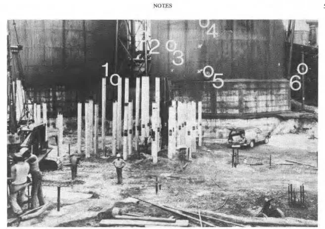
Two camera stations were established 10.0 m apart on stable ground about 14 m outside the piling area. The cameras were supported by scaf- folds 3.7 m above the original ground surface in order to photograph as many piles as possible. Six control points consisting of painted crosses, well defined joints, and bolts (points 3 and 6, 1 and
4,
and 2 and 5 respectively in Fig. 1 ) were established on an existing silo immediately behind the construc- tion area. The control points and camera stations were used to define the reference coordinate system and provide information on the accuracy of the
photogrammetric measurements. Their X-, Y-, and Z-coordinates were determined at the start of construction by surveying with a T2 theodolite. The X-directior, of the coordinate system was parallel to the camera base with the coordinates increasing from the left- to the right-hand camera station. The Y-axis was horizontal and normal to the base with the coordinates increasing from the cameras to the piling area, and the positive Z-axis pointed vertically upwards.
A photographic target consisting of a white cross on a black background and identified by a number was painted on each pile after it was driven (Fig. 1). The line thickness forming the targets was about 25 mm.
A Wild P-3 1 camera with a 100 mm focal length lens and an image format of 1 1 7 mm X 83 mm was used alternatively at each camera station. It was aimed at the centre of the piling area in order to cover the entire area of interest on the photographs. This resulted in a convergence angle 4 of about
15O between the two camera axes. The photo- graphic exposures were made on 3.3 mm thick aerographic plates at 1 week intervals for 5 weeks during the pile driving operations.
The concrete piles installed in the 2.5 m deep excavation projected about 5 m above the floor. In many cases the piles in the foreground obscured targets on other piles. After all piles had been driven, only 30% of the total and 18% of those driven the previous week could be stereoscopically
NOTES 597
FIG. 1. Control points (1-6) and targets (crosses) for terrestrial photogrammetric measurements. (Photo: M. C. van Wijk: Division of Physics, National Research Council of Canada.)
interpreted on the photographs. These percentages, however, were considered sufficient to assess the overall movements of the piles.
A Zeiss Jena Stereocomparator 18 18, equipped
with an Instronics Gradicon readout system, was employed for the photogrammetric analysis using the original negative plates. Photo coordinates were measured for the following points, which were automatically recorded on magnetic tape: ( 1 )
fiducial marks, for defining the camera coordinate system; ( 2 ) points near the edges of the stereo overlap, required for relative orientation; ( 3 ) six
I control points, used for absolute orientation; and
( 4 ) pile targets.
The photo coordinates were transformed to coordinates corresponding to 'normal case' pho- tographs, where the camera axes are parallel to each other and normal to the base, by means of the following equations:
x' =
f
f
sin4
+
x cos+
C11 fcospJ r- .
-
xsin+
y' = J Y
f cos
+
-
x sin4
convergent photographs; x', y' = transformed coordinates, corresponding with 'normal case' pho- tography;
+
= convergence angle; and f = focal length of the camera.The same convergence angle, measured to an accuracy of 1 or 2O, was used for all photographs taken during the pile driving operations. The pre- cise camera orientation and the spatial target coordinates were computed from the transformed coordinates, using the computer program, for rel- ative orientation of near-normal case photographs (Schut 1973). The spatial coordinates were then transformed to the control coordinate system by means of the XYZ transformation program (Schut 1967).
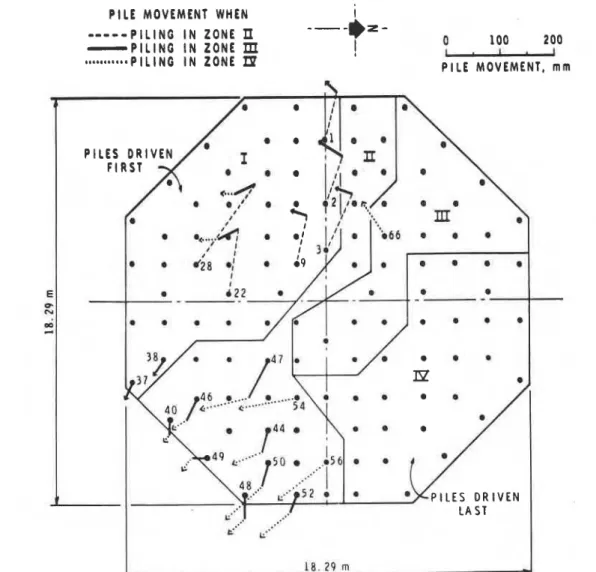
Pile movements were determined from the differ- ences of the X-, Y-, and 2-coordinates, which were derived from photogrammetric surveys ob- tained at different stages of the pile driving program. To illustrate these measurements, Fig. 2 shows the magnitude and direction of horizontal movements observed on installed piles as piling was subsequently completed in each designated zone.
CAN. GEOTECH. J. VOL. 15, 1978
PILE MOVEMENT WHEN
---ex-
1- - - P I L I N G I N ZONE
P
- P I L I N G I N Z O N E
m
a
100 200*a---n-*PILING I N ZONE
LP
I
-
PILE MOVEMENT, m m
FIG. 2. Photogrammetric measurements of horizontal pile movements due to pile driving in successive zones.
coordinates was obtained by comparing the pho- errors of the pile coordinates are within the above togrammetrically determined coordinates of the values. Considering, however, that the movements control points and the camera stations with cor- of the piles are calculated from the change in responding values from field surveys, using the their coordinates, the standard errors then become equation:
v'2
times the above coordinate standard errors or:P I
m = ( ( A h ) /n) 4 m ~ , = 15 mm; m ~ , = 20 mm; and m ~ , = 5 mm. where m = standard error in photogrammetriccoordinates, A = differences between photogram- metric coordinates and those obtained from field surveys, and n = number of points.
The following coordinate standard errors were calculated by analysing the stereo pairs of pho- tographs taken at five different times during the project: m,
=
11 mm; m, = 14 mm; and m, = 4 mm. Since the piles were located between the control points and the camera stations, the standardSummary and Conclusions
Terrestrial photogrammetry proved to be a use- ful technique for recording the movements of driven piles. Because the piles projected about 5 m above the floor of the excavation, the cameras were elevated about 3.7 m above the original ground surface on scaffoIds in order to photograph as many piles as possible. Thus the movements of 30% of the 116 piles driven on the site were recorded. The accuracy of the measured movements was
NOTES 599 m ~ , = 15 mm, m ~ , = 20 mm, and m ~ , = 5 mm with
respect to an orthogonal coordinate system. The technique has many advantages for field use. The photographs can be obtained quickly and if care- fully planned, many observations can be easily obtained as construction progresses, without inter- fering with construction activities.
Acknowledgements
The work was carried out by Terratech Ltd., under Contract No. 31040-4-1872 from the De- partment of Supply and Services, Canada. This paper is a joint contribution from Terratech Ltd., and the Divisions of Physics and Building Research of the National Research Council of Canada.
B o z o z u ~ , M., FELLENIUS, B. H., and SAMSON, L. 1978. Soil disturbance from pile driving in sensitive clay. Canadian Geotechnical Journal, 15(3), pp. 346-361.
MASSARSCH, K. R. 1974. Jordundantrangning vid p%lslagning. Resultat av model Fdrsok. Royal Swedish Academy of En- gineering Sciences, Commission on Pile Research, Report No. 43. (In Swedish.)
-
1975. Deformationsmitningar vid slagning av p%lar. Re- sultat av stereofotogrammetriska matningar. Royal Swedish Academy of Engineering Sciences, Commission on Pile Re- search, Report No. 49. (In Swedish.)SCHUT, G. H. 1967. Block adjustment by polynomial transfor- mations. Photogrammetric Engineering, 33(9), pp. 1042- 1053.
1973. An introduction to analytical strip triangulation, with a FORTRAN program. Revised edition. National Re- search Council of Canada, Division of Physics, (NRC 13148), P-PR 44. 82 p.