HAL Id: hal-02901555
https://hal.archives-ouvertes.fr/hal-02901555
Submitted on 27 Sep 2020
HAL is a multi-disciplinary open access
archive for the deposit and dissemination of
sci-entific research documents, whether they are
pub-lished or not. The documents may come from
teaching and research institutions in France or
abroad, or from public or private research centers.
L’archive ouverte pluridisciplinaire HAL, est
destinée au dépôt et à la diffusion de documents
scientifiques de niveau recherche, publiés ou non,
émanant des établissements d’enseignement et de
recherche français ou étrangers, des laboratoires
publics ou privés.
Artifacts in magnetic force microscopy under in-plane
applied magnetic field: Magnetic bubble as a case study
Ibrahim Cinar, Daniel Lacour, François Montaigne, Vito Puliafito, Sébastien
Petit, Michel Hehn, Giovanni Finocchio, Ozhan Ozatay, Thomas Hauet
To cite this version:
Ibrahim Cinar, Daniel Lacour, François Montaigne, Vito Puliafito, Sébastien Petit, et al..
Ar-tifacts in magnetic force microscopy under in-plane applied magnetic field: Magnetic bubble as
a case study.
Journal of Magnetism and Magnetic Materials, Elsevier, 2020, 500, pp.166296.
Artifacts
in magnetic force microscopy under in-plane applied magnetic
field: Magnetic bubble as a case study
Ibrahim
Cinar
a,b,⁎,
Daniel Lacour
b,
Francois Montaigne
b,
Vito Puliafito
c,
Sebastien Petit Watelot
b,
Michel Hehn
b,
Giovanni
Finocchio
d,
Ozhan Ozatay
e,
Thomas Hauet
baDepartment of Medical Services and Techniques, Karamanoglu Mehmetbey University, 70100 Karaman, Turkey bInstitut Jean Lamour, UMR CNRS-Université de Lorraine, 54011 Nancy, France
c Department of Engineering, University of Messina, Messina, Italy
d Department of Mathematical and Computer Sciences, Physical Sciences and Earth Sciences, University of Messina, Messina, Italy e Department of Physics, Bogazici University, 34342 Bebek, Istanbul, Turkey
The study of magnetic bubble configuration in Co/Ni multilayers circular dots under in-plane magnetic field enlightens two magnetic force microscopy (MFM) measurement artifacts. We demonstrate that any tilt of the magnetic field producing out-of-plane field component due to the inhomogeneity of the MFM set up strongly affects the shape and size of the magnetic bubble independently of the plane field component intensity. Furthermore, MFM signal variations for in-plane magnetic field larger than 0.1 Tesla can only be understood considering MFM tip magnetization rotation. These two artifacts can have strong impact on MFM images and need to be carefully checked for reliable results in imaging skyrmionic structures with MFM under-field.
1. Introduction
Magnetic Force Microscopy (MFM) is considered as an effective method for imaging magnetic configurations in thin films with not only in-plane, but also perpendicular magnetic anisotropy with high re-solution[1–4]. However this powerful technique is not artifact free. In addition to standard artifacts encountered when performing atomic force microcopy[5]a very common one is the sample-tip interaction with can lead to modification of the observed magnetic configuration
[6]. Electrostatic force acting at long range as well as the magnetic force can lead to MFM image misinterpretations[7]. Consequently, it is only when having all the possible artifacts in mind that one can conduct a solid analysis of the acquired MFM images.
Magnetic skyrmionic structure are among most exciting magnetic objects under research subject, nowadays. MFM is a very useful tool to observe these kind of interesting magnetic configurations. Magnetic bubble is also one of them. Only few studies about magnetic bubbles hosted by circular dots can be found in the literature. Ref.[8]provides some theoretical stability calculations, while more recently skyrmionic type magnetic configurations behavior under external perpendicular magneticfield were experimentally studied[9,10].
Generally, MFM is used to image magnetic domains in the absence of an external magnetic field. However, it has also proven to be a
powerful tool for imaging of magnetic domains in the presence of an external magneticfield[11,12]. In this study, we have used MFM with in-plane external magneticfield to observe magnetic bubble behavior in Ta (50 Å)/Pt(100 Å)/[Co(2 Å)/Ni(6 Å)]8/Co(2 Å)/Pt (50 Å) thinfilm patterned circular dots. We used [Co/Ni] multilayer in our study be-cause it has very well controlled intrinsic magnetic properties[13–17]
with limited damping, high perpendicular anisotropy, high spin-polar-ization and moderate magnetspin-polar-ization. In our previous study, nucleation and stability of magnetic bubble was showed in an assembly of pat-terned dots[17].
Here MFM measurements show that, even in the presence of a large in-plane (IP) external magneticfield, any slightest out-of-plane (OOP) magneticfield component affects the bubble shape and size. Moreover, we observed tip magnetization rotation from out-of-plane to in-plane while applying in-plane magneticfield. We discuss the impact of such tip magnetization rotation on the MFM image.
2. Experimental procedure
We study here a multilayer made of cobalt (Co) and Nickel (Ni) layers with 8 repetitions Ta (50 Å)/Pt(100 Å)/[Co(2 Å)/Ni(6 Å)]8/Co (2 Å)/Pt(50 Å). The multilayer was deposited using an AJA magnetron sputtering system on thermally oxidized Si (100 nm SiO2) wafers at
Journal of Magnetism and Magnetic Materials 500 (2020) 166296
room temperature. During deposition, the substrate was rotated for uniformity at about 1.5 Hz. Co was sputtered at 50 W with a deposition rate of 0.23 Å/sec and Ni was sputtered at 50 W with a deposition rate of 0.28 Å/sec using an Argon pressure of 5 mTorr. The multilayer was grown on top of a 50 Å Ta and 100 Å Pt buffer layers to get (1 1 1) texture, and covered by a 50 Å Pt capping layer to prevent oxidation. [Co/Ni] film was patterned to circular dots, with diameters ranging from 1.5μm, by combining electron beam lithography and ion beam etching. The distance between dots (center-to-center) was set to be four times their diameter in order to have negligible dipolar interactions.
The magnetic properties of the fullfilms at room temperature were determined by using Vibrating Sample Magnetometer (VSM), on a Quantum Design physical properties measurement system (PPMS). Magnetic domain patterns were observed using Magnetic Force Microscopy (MFM), on an Asylum research AFM, MFP-3D Infinity in-strument. For MFM imaging, we used Bruker low moment (LM) MESP tips to avoid artifacts due to tip/sample interaction.
3. Results and discussion
Co/Ni thinfilm sample magnetization loops versus in-plane and out-of-plane magneticfield for our sample are shown inFig. 1(a) and (b). Saturation magnetization is measured to be 820 ± 20 kA/m. More-over, our thinfilm exhibits a clear perpendicular magnetic anisotropy. The anisotropy constant is obtained from the hard axis in-plane loop as 6.9 ± 0.1 105J/m3.
Atomic force microscopy (Fig. 1(c)) image indicates that the pat-terned dot has well defined circular shape. Bubble stabilization in the dot array is achieved through AC in-planefield demagnetization, where the maximumfield Hmaxcan be adjusted to optimize the bubble nu-cleation statistics as shown in our previous work[17]. Besides Hmax, dot diameter is another factor affecting bubble nucleation and stability in a patterned dot array[17].Fig. 1(c) shows stable magnetic bubble for 1.5μm diameter patterned dot in 2D and its magnetization direction.
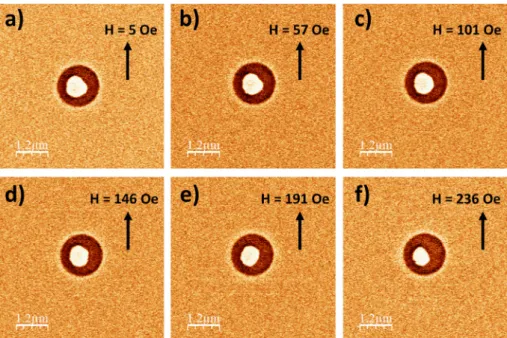
Fig. 2a–f show MFM images of one dot hosting a single magnetic
bubble under in-plane magneticfield whose amplitude ranges from zero to 240 Oe. One MFM image was taken every 15 Oe increment. The bubble is found to shrink as the in-plane magneticfield increases. The
diameter of the bubble is around 800 nm at the beginning and after applying 236 Oe, the diameter of bubble is around 600 nm. Also, the bubble wall motion is anisotropic. The same procedure was conducted for different dots among the same array of dots and with the same in-itial demagnetization process.
InFig. 3a–f, another sample is shown with in-plane magnetic field values ranging from zero to 609 Oe. Here, surprisingly, we observed enlargement of magnetic bubble (instead of shrinking) when thefield amplitude increases. Bubble area at 609 Oe is nearly twice the one at zerofield.
The difference in the behavior of the two samples can be understood (i.e. enlarging or shrinking bubble with in plane external magnetic field), by considering the dot position where the applied field direction is not exactly the same as one would assume in the experiments for all samples. It is easy to see this in the MFM set up schematic inFig. 4. Depending on sample position, the applied magneticfield has both IP and/or OOP magneticfield components, InFig. 4, region 1 and 2 have opposite perpendicular magneticfield components. Therefore in case 1, bubble shrinks whereas, in case 2, bubble expands. From the experi-ment under just perpendicular magneticfield, magnetic bubble is af-fected easily under OOP applied magneticfield and around 60 Oe (there is sample to sample variations like for some samples 50 Oe and for some 75 Oe) is enough for destroying the bubble (annihilating or enlarging and then becoming single domain in disk). Such low depinningfield as compared to 210 Oe coercivityfield inFig. 1(a) is linked to the fact that bubble stability here only comes from the strayfield in the dot. It does not originate from local strong anisotropy defect which could act as pinning center. Therefore an OOP field as small as 60 Oe is able to overpass the stabilizing strayfield.
For instance in the experiment described inFig. 4, when considering a magnetic field tilt of 2° with respect to the sample plan, an OOP component of 20 Oe/7 Oe is present for an IP measured magneticfield equal to 600 Oe/200 Oe. Such values are high enough to enlarge or reduce the bubble size depending on the dot position with respect to pole pieces (seeFig. 4.). The sign of the OOP magneticfield can even change depending on these positions (e.g. see region 1 and 2 inFig. 4) leading either to a bubble expansion or reduction as observed inFigs. 2
Fig. 1. Co/Ni thinfilm magnetization versus magnetic field measured by VSM under 0.5T out-of-plane field (a) and 2T in-plane field (b) respectively. (c) AFM and MFM images of 1.5 µm diameter Co/Ni circular dot after AC in-plane externalfield demagnetization.
and 3.
MFM images of the same dot as inFig. 3are presented inFig. 5for IP field intensities larger than 600 Oe. At 980 Oe, MFM contrasts changed suddenly. For magneticfields below this threshold value the MFM contrasts associated with the bubble edges consist of a white ring directly surrounded by a dark one. Beyond the threshold value the bubble edge signature is associated with a contrast having a dark top part and white down part.
One could think that such a change is related to a uniform tilt of the dot magnetization. But,first, the transition is abrupt (less than 15 Oe). Second the MFM pattern due to a moment tilting inside the bubble and the outer region would notfit with the observed MFM signal. On the contrary, as demonstrated below, a switch of tip magnetization from OOP to IP direction induced by the applied magneticfield is consistent with the observed MFM signal change.
In the following we determined the expected MFM phase signal from a bubble in an extendedfilm, considering an MFM tip magnetized
either IP or OOP. To do so, we calculated the derivative of the magnetic force between tip and sample, which we normalized by the magnetic moment of the tip (mtip):
∂ ∂ = ∂ ∂ + ∂ ∂ m F z cos θ H z sin θ H z 1 ( ) ( ) tip mag 2 y z 2 2 2 (1) Hyand Hzare the magnetic strayfield components in the y direction (appliedfield direction) and z direction (direction perpendicular to the sample plane) andθ is the angle of mtipwith respect to y.
According to previous studies our bubble edges are Bloch walls
[17,18]. The y and z strayfield components can be calculated from the following equations[19]using an arctan(y/w) domain wall profile:
⎜ ⎟ = ⎛ ⎝ + + + + ⎞ ⎠ H y z M arctan xh z w z w h x ( , ) 4 ( )( ) z s 2 (2)
Fig. 2. MFM images of magnetic bubble in a dot for different in-plane external magnetic field values.
⎜ ⎟ = ⎛ ⎝ + + + + + ⎞ ⎠ H y z M ln z w h x z w x ( , ) 2 ( ) ( ) y s 2 2 2 2 (3) where h is the thickness of sample, w the DW width, and Mssaturation magnetization, and z the distance over the surface. Substituting Eqs.(2)
and (3)in Eq.(1)allows to compute the expected MFM contrast in the two cases of interest.
Results from this computation for the OOP and IP magnetized tip respectively as well as experimental MFM profiles extracted from
Fig. 5a) and b are reported inFig. 6a) and b). Both experimental profiles are well reproduced by the numerical calculations. This demonstrates that the recorded abrupt change of the MFM signal is consistently ex-plained by a switch of the tip magnetization from OOP to IP.
Fig. 4. Schematic illustrations of MFM measurement system from side view and top view. The pole pieces are represented in clear blue. Dot diameter is 1 µm. (For interpretation of the references to colour in thisfigure legend, the reader is referred to the web version of this article.)
Fig. 5. MFM images of magnetic bubble in a dot for different in-plane external magneticfield values.
Fig. 6. Calculated MFM signals of magnetic bubble and experimental results for out of plane a) at 968 Oe inFig. 5a and in plane b) at 982 Oe inFig. 5b. The results presented are obtained from afit using with h = 28 nm, w = 60 nm as free parameters. The Msvalue was taken from measurements presented earlier
while the distance z over the surface wasfixed to 30 nm during our measure-ments.
4. Conclusion
We performed MFM measurements under applied magneticfield on magnetic bubbles hosted by circular dots. First, both an increase and decrease of the bubble sizes depending on sample position is reported. Such behavior is attributed to a measurement artifact due to slight misalignment of the magneticfield with respect to sample surface. At higher magneticfield, we record a drastic change of the MFM contrast associated with the bubble edges. This second observation of the bubble is attributed to a switch of the tip magnetization as verified with nu-merical calculations. These two measurement artifacts should be taken into account when performing magnetic force microscopy under ap-plied magneticfield.
Declaration of Competing Interest
The authors declare that they have no known competingfinancial interests or personal relationships that could have appeared to influ-ence the work reported in this paper.
Acknowledgments
This work was supported by TUBITAK (Grant No: 114F318) and TUBITAK-BİDEB 2214/A Grant.
References
[1] U. Hartman, Magnetic force microscopy, Annu. Rev. Mater. Sci. 29 (1999) 53–87. [2] M.S. Pierce, J.E. Davies, J.J. Turner, K. Chesnel, E.E. Fullerton, J. Nam,
R. Hailstone, S.D. Kevan, J.B. Kortright, Kai Liu, L.B. Sorensen, B.R. York, O. Hellwig, Influence of structural disorder on magnetic domain formation in perpendicular anisotropy thinfilms, Phys. Rev. B 87 (2013) 184428. [3] Gabriel Bochi, H.J. Hug, D.I. Paul, B. Stiefel, A. Moser, I. Parashikov,
H.-J. Güntherodt, R.C. O'Handley, Magnetic domain structure in ultrathinfilms, Phys. Rev. Lett. 75 (1995) 1839.
[4] V. Gehanno, A. Marty, B. Gilles, Y. Samson, Magnetic domains in epitaxial ordered FePd(001) thinfilms with perpendicular magnetic anisotropy, Phys. Rev. B 55 (1997) 12552.
[5] Atomic Force Microscopy: Edition 2, Bert Voigtländer May 23, 2019 Springer. [6] G. Ciuta, Frédéric Dumas-Bouchiat, Nora Dempsey, Olivier Fruchart, Some aspects
of magnetic force microscopy of hard magneticfilms, IEEE Trans. Magn. 52 (9) (2016) 6500408.
[7] Livia Angeloni, Daniele Passeri, Melania Reggente, Diego Mantovani, Marco Rossi, Removal of electrostatic artifacts in magnetic force microscopy by controlled magnetization of the tip: application to superparamagnetic nanoparticles, Sci. Rep. 6 (2016) 26293.
[8] C. Moutafis, S. Komineas, C.A.F. Vaz, J.A.C. Bland, T. Shima, T. Seki, K. Takanashi, Magnetic bubbles in FePt nanodots with perpendicular anisotropy, Phys. Rev. B 76 (2007) 104426.
[9] Olivier Boulle, Jan Vogel, Hongxin Yang, Stefania Pizzini, Dayane de Souza, Andrea Locatelli Chaves, Tevfik Onur Menteş, Alessandro Sala, Liliana D. Buda-Prejbeanu, Olivier Klein, Mohamed Belmeguenai, Yves Roussigné, Andrey Stashkevich, Salim Mourad Chérif, Lucia Aballe, Michael Foerster, Mairbek Chshiev, Stéphane Auffret, Ioan Mihai Miron, Gilles Gaudin, Room-temperature chiral magnetic skyrmions in ultrathin magnetic nanostructures, Nat. Nanotechnol. 11 (2016) 449–454. [10] Yu. Xiuzhen, Yusuke Tokunaga, Yasujiro Taguchi, Yoshinori Tokura, Variation of
topology in magnetic bubbles in a colossal magnetoresistive manganite, Adv. Mater. 29 (2017) 1603958.
[11] C. Bran, A. Butenko, N. Kiselev, U. Wolff, L. Schultz, O. Hellwig, U.K. Rößler, A.N. Bogdanov, V. Neu, Evolution of stripe and bubble domains in anti-ferromagnetically coupled [(Co/Pt)8/Co/Ru]18 multilayers, Phys. Rev. B 79 (2009) 024430.
[12] M. Ghidini, G. Zangari, I.L. Prejbeanu, G. Pattanaik, L.D. Buda-Prejbeanu, G. Asti, C. Pernechele, M. Solz, Magnetization processes in hard Co-rich Co-Ptfilms with perpendicular anisotropy, J. Appl. Phys. 100 (2006) 103911.
[13] S. Girod, M. Gottwald, S. Andrieu, J. McCord, S. Mangin, E. Fullerton, J.M.L. Beaujour, B.J. Krishnatreya, A.D. Kent, Strong perpendicular magnetic ani-sotropy in Ni/Co(111) single crystal superlattices, Appl. Phys. Lett. 94 (2009) 262504.
[14] S. Mangin, Y. Henry, D. Ravelosona, J.A. Katine, Eric E. Fullerton, Reducing the critical current for spin-transfer switching of perpendicularly magnetized nano-magnets, Appl. Phys. Lett. 94 (2009) 012502.
[15] D.P. Bernstein, B. Brauer, R. Kukreja, J. Stohr, T. Hauet, J. Cucchiara, S. Mangin, J.A. Katine, T. Tyliszczak, K.W. Chou, Y. Acremann, Nonuniform switching of the perpendicular magnetization in a spin-torque-driven magnetic nanopillar, Phys. Rev. B (R) 83 (2011) 180410.
[16] F. Gimbert, L. Calmels, S. Andrieu, Localized electron states and spin polarization in Co/Ni(111) overlayers, Phys. Rev. B 84 (2011) 094432.
[17] T. Liu, V. Puliafito, F. Montaigne, S. Petit, C. Deranlot, S. Andrieu, O. Ozatay, G. Finocchio, T. Hauet, Reproducible formation of single magnetic bubbles in an array of patterned dots, J. Phys. D Appl. Phys. 49 (2016) 245002.
[18] S. Le Gall, N. Vernier, F. Montaigne, A. Thiaville, J. Sampaio, D. Ravelosona, S. Mangin, S. Andrieu, T. Hauet, Effect of spin transfer torque on domain wall motion regimes in [Co/Ni] superlattice wires, Phys. Rev. B 95 (2017) 184419. [19] M. Gottwald, M. Hehn, D. Lacour, T. Hauet, F. Montaigne, S. Mangin, P. Fischer,
M.-Y. Im, A. Berger, Asymmetric magnetization reversal in dipolarly coupled spin valve structures with perpendicular magnetic anisotropy, Phys. Rev B 85 (2012) 064403.