Publisher’s version / Version de l'éditeur:
Vous avez des questions? Nous pouvons vous aider. Pour communiquer directement avec un auteur, consultez la première page de la revue dans laquelle son article a été publié afin de trouver ses coordonnées. Si vous n’arrivez pas à les repérer, communiquez avec nous à [email protected].
Questions? Contact the NRC Publications Archive team at
[email protected]. If you wish to email the authors directly, please see the first page of the publication for their contact information.
https://publications-cnrc.canada.ca/fra/droits
L’accès à ce site Web et l’utilisation de son contenu sont assujettis aux conditions présentées dans le site
LISEZ CES CONDITIONS ATTENTIVEMENT AVANT D’UTILISER CE SITE WEB.
Canadian Building Digest, 1970-05
READ THESE TERMS AND CONDITIONS CAREFULLY BEFORE USING THIS WEBSITE. https://nrc-publications.canada.ca/eng/copyright
NRC Publications Archive Record / Notice des Archives des publications du CNRC :
https://nrc-publications.canada.ca/eng/view/object/?id=d065a04d-afe1-4289-abd7-d2e5f99048c7
https://publications-cnrc.canada.ca/fra/voir/objet/?id=d065a04d-afe1-4289-abd7-d2e5f99048c7
NRC Publications Archive
Archives des publications du CNRC
For the publisher’s version, please access the DOI link below./ Pour consulter la version de l’éditeur, utilisez le lien DOI ci-dessous.
https://doi.org/10.4224/40000822
Access and use of this website and the material on it are subject to the Terms and Conditions set forth at
Cladding problems due to frame movements
Canadian Building Digest
Division of Building Research, National Research Council Canada
CBD 125
Cladding Problems Due to Frame
Movements
Originally published May 1970 W.G. Plewes
Please note
This publication is a part of a discontinued series and is archived here as an historical reference. Readers should consult design and regulatory experts for guidance on the applicability of the information to current construction practice.
Problems with cladding are frequently the result of movement of supporting concrete building frames due to creep and shrinkage, a source of trouble that is often not recognized. Although frame deformation is frequently the prime cause, diagnosis is difficult owing to the fact that workmanship, materials, moisture, temperature and design factors aggravate the situation. The physical and chemical mechanisms involved in creep and shrinkage as natural phenomena were discussed in CBD 119. It is the purpose of the present Digest to draw particular attention to their effects on cladding.
Even to experienced and meticulous designers, the adverse effects of creep and shrinkage on claddings may appear to be a relatively new problem. This is understandable for a number of reasons:
a. Although creep and shrinkage almost certainly caused difficulty decades ago, their contributing influence was not well understood. Most knowledge of creep, and to some extent shrinkage, is based on research, the bulk of which has been done over the last 20 years. As a result, the majority of failures caused by creep and shrinkage were considered to be the result of "building settlement."
b. In former days, buildings tended to be of rather stereotyped, heavy beam and girder
construction, particularly those of reinforced concrete. Today's buildings are commonly much higher and have larger spans. Stronger materials and better quality control permit substantial increase in stresses and these, in turn, result in thinner, more flexible members. Flat plate and cantilever construction have become common, often with light spandrels or none at all. Without previous experience, designers have not been led to anticipate the adverse results of creep and shrinkage on claddings.
c. New cladding materials have introduced problems that could only be discovered through experience. The thick masonry panel walls of older buildings were almost structural in
themselves and capable, in many cases, of resisting the forces involved. Thinner walls, harder units and mortars, and the omission of ledger angles have contributed to troubles. New types of cladding such as prefabricated panels have been common for a relatively short time and the consequences of frame movements on them are just coming to light.
d. Finally, and most important, basic research into creep and shrinkage was done on small laboratory specimens under controlled conditions. As both creep and shrinkage are affected by the volume/surface ratio, percentage of reinforcement, age at loading, sequence of loading and ambient relative humidity, the application to structures of the results of tests on small laboratory specimens is difficult; and the range of effects from structure to structure varies greatly. It is only in very recent years, particularly at the present time, that research findings have been translated into practical methods for predicting creep and shrinkage effects in actual design (1,2).
Typical Effects
A 12-inch square column 10 ft high without any steel might typically shorten about 0.05 inch as a result of shrinkage and creep. With 4 per cent longitudinal steel added, this would be reduced to about 0.025 inch owing to the restraint imposed by the steel. Loading at an age earlier than 28 days, doubling or halving the size of the column, or a difference in ambient relative humidity could cause the shortening to be half or twice that amount.
It is evident that even in a modest 60-ft high building the cumulative shortening of the frame could amount to as little as 0.10 inch or more than 0.6 inch. In any case, if a stiff cladding skin is rigidly attached to the frame, it will be heavily loaded by a shearing action between the skin and the frame. In addition, surface temperature variations of the outer skin can aggravate the situation.
Shrinkage and creep are not unidimensional. Shrinkage can act in three dimensions and creep will affect the deflection of spanning members such as spandrels profoundly (see CBD 54). It is not possible to give simple rules for predicting the performance of all possible designs, but it may be useful to illustrate possible effects by discussing a few known cases.
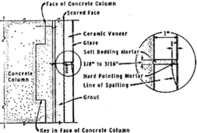
Example 1. The situation shown in Figure 1 is perhaps the clearest example of the foregoing
discussion. Concrete columns are clad with 1-inch thick, high quality, ceramic veneer. The backs of the panels were scored and the concrete column faces keyed so that grout poured into the space between them bonded the veneer firmly to the columns. Following completion of the building, considerable spalling of the glazed face occurred along the horizontal joints. In situ strain measurements showed that the veneer was stressed to at least 3,000 psi by column shortening due to creep and shrinkage. Surprisingly, the damaged portion was an extension of an almost identical structure about 30 years old that had not shown this effect. The only difference between the structures was that joints in the new construction were pointed with an extremely hard pointing mortar to a depth of ¼ inch. This had the effect of concentrating the stress in the veneer on a rigid ¼ inch strip along the surface of the joint, thus causing the spalling. The slower pace of construction of former times may also have had a mitigating effect, allowing more shrinkage and creep to take place before the veneer was applied.
Example 2. In another building investigated by DBR/NRC the bays between floor slabs and
columns of a 10-storey apartment building were infilled with concrete block panel walls. The clay brick facing was tied to the concrete block wall with masonry headers and was continuous outside the column face line for the full 10 storeys, except where the facing projected completely from the foundation and terminated at the foundation level on a 3/16-inch thick ledger plate. Shrinkage of the frame and the block walls could not be accommodated by relatively rigid, non-shrinking facing, nor by rigid header connections. As a result, differential shearing action caused a sudden failure of a 2-storey high section of the brick cladding, shearing through all the header bricks and bending the ledger plate. The entire facing had to be replaced. Copeland (3), discusses similar details said to cause cracking, spalling and splitting of facing wythes because of too-rigid connection to the frame.
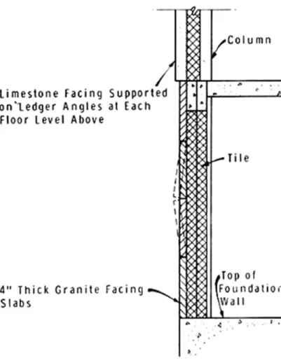
Example 3. The first storey of an 8-storey office building was faced with 4-inch thick granite
slabs and the upper storeys with limestone slabs supported on ledger angles at each floor level (Figure 2). The granite slabs were fastened to tile masonry back-up by means of straps and dowel pins. After a few years' occupation the granite slabs had moved outward about ¾ inch. Before remedial action could be taken, two of the slabs suddenly bulged about 2 inches. Investigation revealed that shortening of the frame from shrinkage and creep had heavily loaded the building skin and finally caused buckling. Many other signs of shortening could be observed about the building in the form of cracks and rotations.
Figure 2. Buckling of stone veneer due to creep and shrinkage in frame.
Example 4. Vertical shortening of columns is not the only effect of shrinkage and creep. There
is well documented evidence that creep deflections of slabs and beams under long-term load can be 2½ to 3 times the elastic deflection that occurs when the load is first applied. As live loads are normally light and of short duration, it is dead load deflection that usually predominates in such cases. In one 9-storey building having no spandrel beams at the edges of
the floor slabs the edge deflection caused 1/16-inch vertical cracks to open in the masonry panel walls at the centre of each bay panel. Similar cracks appeared horizontally at each floor level from slab deflection.
Shrinkage can act in any direction and horizontal shrinkage opened a vertical crack the full height of the building at the end return walls, a common occurrence in such cases. As a result of this cracking, copious quantities of water flowed into the building with every driving rain storm.
Example 5. Precast concrete wall panels are not exempt from such difficulties if creep is
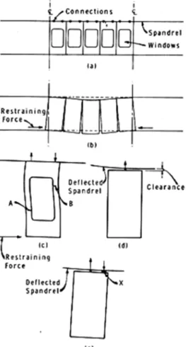
neglected in computing beam or slab deflections. Consider a series of five panels hanging in a typical bay from the upper spandrel by two-point support (Figure 3(a). If the spandrel deflects too much under the wall and slab dead load, there will be a tendency for the panels to spread fanwise, as is shown in Figure 3(b) in a somewhat exaggerated way. This cannot happen in practical situations; the reaction of panels in adjacent bays, bottom connections, or locating pins at the bottom will prevent it. Whatever preventing force is present will hold the panel close to its vertical alignment. As shown in Figure 3(c), however, there will be a tendency for the panel rails to bend or crack and to develop a twisting couple at the top connections. These twisting couples will resist the tendency of the spandrel to deflect, so that one might not be aware that the spandrels are too flexible and that the panels are stressed.
Figure 3. Stressing of panel cladding due to deflection tendency of spandrel.
In one such case cracks that occurred in the panel rails fitted such a mechanism (see A and B, Figure 3(c)). This permitted moisture to penetrate cracks in the panels during rain storms, even before the building was finished. A single central connection would enable panels to hang vertically at all times, provided the clearance shown in Figure 3(d) was sufficient and open. Central connections were, in fact, provided in this building, but mortaring of the joints defeated
their potential benefits, as shown in Figure 3(e). Shims accidentally left in place would also cause undesirable reaction points.
Preventive Measures
These descriptions of only a few of the many cases investigated by the Division should indicate the variety of effects that can occur. If designers are to avoid such pitfalls, preventive measures are necessary. First and foremost, designers must estimate the creep and shrinkage that can occur, using information now available in the technical literature (1,2). Even an approximate estimate will be better than ignoring the effects altogether. Once this is done, the solution becomes a matter of design. Stiffer spanning members, flexible connections, non-rigid caulking, or open joints may all be employed to avoid annoying and expensive problems. Selection of materials and proportions of concrete mixes having lower than average shrinkage and creep properties can also be of benefit.
References
1. Branson, Den. E. Design Procedures for Computing Deflections. J. Amer. Concrete Inst., Vol. 65, No. 9, Sept. 1968, p. 730-742.
2. Fintel, M. and F. R. Khan. Effects of Column Creep and Shrinkage in Tall Structures -- Prediction of Inelastic Column Shortening. J. Amer. Concrete Inst., Vol. 66, No. 12, Dec. 1969, p. 957-967. 3. Copeland, R. E. Flexible Anchorage of Masonry Walls. Concrete Products, Vol. 71, No. 7, July