Design of High Performance Hybrid Transmissions
by
Daniel S. Dorsch
S.B., Massachusetts Institute of Technology (2012)
S.M., Massachusetts Institute of Technology (2015)
Submitted to the Department of Mechanical Engineering
in partial fulfillment of the requirements for the degree of
Doctor of Philosophy in Mechanical Engineering
at the
MASSACHUSETTS INSTITUTE OF TECHNOLOGY
September 2019
©
Massachusetts Institute of Technology 2019. All rights reserved.
Author...Signatureredacted
Department of Mechanical Engineering
August 23, 2019
Certified by...
Signatureredacted
...
Amos G. Winter, V
Associate Professor of Mechanical Engineering
Signature redactedThesis
Supervisor
Accepted by...
MASSACHETS INSGTITUTE OF TECHNOLOGY
SEP 19 2019
Nicolas Hadjiconstantinou
Professor of Mechanical Engineering
Graduate Officer
m
Design of High Performance Hybrid Transmissions
by
Daniel S. Dorsch
Submitted to the Department of Mechanical Engineering on August 23, 2019, in partial fulfillment of the
requirements for the degree of
Doctor of Philosophy in Mechanical Engineering
Abstract
This thesis explores the design, development, and evaluation of transmission systems for integration into high-performance hybrid (internal combustion engine (ICE) and electric motor) vehicles. Traditional hybrid vehicle designs often fall into one of two categories. Every day road vehicles typically utilize hybridization for increased drivetrain efficiency, including traits such as low speed electric drive and regenerative braking. Alternatively, performance cars have typically utilized the electric motor functionality for increased performance. By using a new framework for analyzing the elements and their function within a propulsion system architecture, advanced hybrid architectures that allow for both high efficiency and increased performance are presented. A two-motor, clutchless hybrid transmission concept was developed. An analysis of driving modes available demonstrates the utility in a high-performance vehicle, increasing the performance and efficiency of the drivetrain. A second, dual-shaft, single motor, clutchless transmission concept is presented, with the benefits and drawbacks of this architecture compared to the two-motor architecture, and a traditional ICE only transmission.
The final part of this thesis presents a novel, two-speed electric motor system that could be integrated within a conventional ICE automated manual transmission. This system utilizes custom sensors for tracking the position of the dogteeth within the two-speed shift synchronizer. Electric motor control is used to synchronize mo-tor speed during a shift event, as the inertia of the electric momo-tor is too large for friction synchronization alone to be sufficient. This strategy removes the tradeoff that currently exists for optimal shift actuator design (larger pistons result in faster speed synchronization but slower actuation motion during other phases of a shift) and results in overall faster gearshifts. Dogtooth tracking allows for firing of the shift actuator at the proper moment, ensuring no collision between dogteeth and allow-ing for faster shifter motion than with a traditional synchronizer. An experimental setup was developed to characterize shift performance. Full gearshifts can be made successfully utilizing speed matching and dogtooth tracking, validating the described shift control method and allowing for improved, frictionless synchronizer designs. The
developments described in this work will lead to a new generation of hybrid vehicles, designed for high-performance and increased efficiency.
Thesis Supervisor: Amos G. Winter, V
Acknowledgments
I would like to thank the following people and organizations for their contributions to my work:
" Natasha Wright - thank you for your help on everything with my research and thesis. Without all of your help this would not have been possible. I have enjoyed our time together in the lab and activities around Boston, and look forward to the many new adventures to come!
* Thank you Franco Cimatti, Andrea Canaparo, Fabrizio Favaretto, and Luca Splendi for your information and help during this project. It has been great meeting with you and learning more about high-performance automobiles.
" Amos Winter, words cannot really capture how much fun I have had and how
much I have learned from you over the last ten years working together. I am sure my next job won't have quite the same adventures with my supervisor, assume we will not get stuck on skis across an international border, fly on a tiny airplane through Guatemala, and hopefully I will not lose any gas caps, but it has been a blast! Thank you for building and running a lab where you care about the students and demonstrate this continuously. As I have seen at MIT, this is not always the case, and I value the amount of time and care you put into each of your students, and their lives. I look forward to talking about engineering projects as we look for topics to work on together in the future, comparing notes on cars we own or want to buy, and updates on life and work. You are always welcome in MN! Thank you for your help getting everything together over the last few weeks, even with your hectic travel schedule. Congrats on tenure and I look forward to hearing about your exciting research projects in the future!
" Thank you to my committee, Franco Cimatti, Maria Yang, and Sangbae Kim
for your help and guidance through my PhD. Your insight and wisdom has helped me think about day-to-day issues and to shape my work and broaden the scope beyond designing for a single vehicle.
" Thank you Jake Jurewicz, Guillermo Pamanes, Young Suk Jo, Patricia Yen,
Joshua Siegel, and Chad Jacoby for the initial development of the first archi-tecture in MIT course 2.76 in Fall 2014. Having as many excellent engineers working on a project together and excited about the challenges is a fun place to be.
" Thank you Sahil Shah, Victor Prost, Zackary Eubanks, Paige Reiter, Daria Bondarchuk, and Yu Hua for your work on the second architecture in MIT course 2.76 in Fall 2015. You took the first architecture and the challenges, and improved on it greatly, even when that seemed difficult at the time.
* In no specific order, thank you to Simone Gelmini, Shane Pratt, Kameron Conforti, Victor Prost, Sahil Shah, Charlie Wheeler, Dan Gilbert, Julia Sokol, Raghav Aggarwal, Josh Wiens, Murthy Arelekatti, Sebastian Ahling, Michael Buchman, and Tyler Hamer for your technical help with this project. All of you are good friends, and I value your willingness to help me through the challenges of a PhD.
" Thank you Joe Teja and Jonathan Tong for your help with the patents. The
late nights together and brainstorming about how to best describe my work were fun. Thank you for helping with patents with last minute notice, and for working around my ever changing schedule while finishing my PhD.
* Thank you to my family for your support of me as a student starting as a child, and over the last eleven years at MIT. Thank you for everything you have and continue to do for me. I came to MIT with two suitcases and we are coming back with two moving trucks. I look forward to spending more time together now that I will be living closer to home.
" Members of GEAR Lab, it has been great getting to know each of you. I have
enjoyed working on projects, brainstorming together, traveling with you, and becoming friends. Thank you for putting up with my constant rearranging of lab, working on my car, and storage of stuff everywhere. I will miss the lab, but the people in lab I will miss the most. I look forward to keeping in touch in the future.
• Thank you to all of the technical staff in the teaching spaces and shops at MIT. I have learned a lot from each of you and enjoyed spending time together talking about machines, manufacturing techniques, and gaining wisdom from you. I enjoy spending time working together on projects, and look forward to showing you my house shop if you are ever in town. Mark Belanger, I enjoyed working together, and learning to machine in Edgerton Student Shop, talking about machines, life, hobbies, and your family. Pat McAtamney, thank you for everything. It was fun working with you in LMP and the Area 51 shop.
* Thank you to all of the students who have worked with me as UROPs. It has been fun getting to know you, learning more about you, and teaching you more about my research.
" MIT MakerWorkshop thank you for your support of my research. The ability
to machine in a shop where I can work in the evening, work together with peers, and have the ability to do what I need to get a project done is great. Thank you to all of the mentors, it has been great working together, creating new events and programs, and building a better space for students.
I am also grateful to the following sources who have provided financial support for this work:
" The company partner, for providing funding for this work.
" MIT Undergraduate Research Opportunities Program, for funding to cover the UROP students who worked with me.
" National Science Foundation Graduate Research Fellowship Program, for the graduate fellowship to cover a portion of my tuition during my graduate work. " Mechanical Engineering, for a graduate fellowship for one semester during my
Contents
1 Introduction
1.1 Background . . . . 1.2 Emissions Regulations Drive
1.3 Types of Hybrids . . . . 1.4 Performance Hybrids.
1.5 Dual Clutch Transmission
1.6 Outline of thesis . . . . the
. . . . Need for Hybridization
. . . . . . . . . . . . . . . .
2 A Framework and Case Studies for Designing Novel High-Performance
Hybrid Transmissions 21
2.1 Minimum Part Count Design Framework . . . . 22
2.2 Two-Motor Clutchless Architecture . . . . 28
2.2.1 Two-Motor Clutchless Architecture Prototype . . . . 35
2.3 Single Motor Architecture . . . . 38
2.3.1 City Driving Range Analysis . . . . 40
2.3.2 Single Motor Prototype . . . . 44
2.4 Conclusions . . . . 46
3 Design and Experimental Validation of a Position Tracking Gearshift System 49 3.1 Introduction . . . . 50
3.1.1 Need for a Two-Speed System . . . . 50 13 13 14 14 16 17 20
3.1.2 Problem Statement . . . . 3.2 Concept Architecture . . . . 3.2.1 Transmission Architecture . . . . 3.2.2 Friction Synchronizer . . . .
3.2.3 Traditional Gearshift Sequence . . . .
3.2.4 New Features Versus a Typical Transmission . . . . .
3.2.5 Synchronizer Torque Versus Motor Torque . . . .
3.2.6 Shift Event Motion . . . .
3.2.7 Dogtooth Tracking . . . .
3.3 Sensing and Control of Shift . . . .
3.3.1 Full Shift Event with Motor Synchronization . . . . .
3.3.2 Physics-Based Shifting Model for Dogtooth Tracking
3.3.3 State Machine Function and Shift Logic . . . .
3.3.4 Sensing Methodology . . . .
3.4 Experimental Setup . . . . 3.4.1 Overview of Setup . . . . 3.4.2 Sensor Ring Fabrication . . . . 3.4.3 Magnetic Field Sensing . . . . 3.4.4 Installation Flexibility . . . . 3.4.5 Motors . . . . 3.4.6 Actuator . . . . 3.4.7 Controller . . . . 3.4.8 Electronics . . . . 3.4.9 Signal Processing . . . . 3.4.10 Testing Procedure . . . .
3.5 Results and Discussion . . . .
3.5.1 Validation of Benchtop Functionality
3.5.2 Scaling to Full Vehicle . . . .
3.5.3 Further Applications . . . . . . . 51 . . . 52 . . . 52 . . . 53 . . . 53 . . . 55 . . . 56 . . . 57 . . . 59 . . . 61 . . . 61 . . . 63 . . . 67 . . . 70 . . . 73 . . . 73 . . . 73 . . . 76 . . . 76 . . . 77 77 . . . . 78 . . . . 80 . . . . 8 1 . . . . 83 . . . . 86 . . . . 88 . . . . 9 6 . . . . 96
3.6 Conclusions . . . .
4 Conclusions 105
4.1 Future W ork . . . . 107 97
Chapter 1
Introduction
This thesis proposes methods of designing novel transmissions for high-performance hybrid vehicles. By considering the key transmission and auxiliary components and their functionality within a drivetrain, two clutchless architectures are developed and tested. These architectures can meet the needs for a performance vehicle, and are worthy of further development. Additionally, a two-speed position tracking shifting system for drivetrain electrification is presented. This system was designed, built, and tested to validate new shifting methods, with the goal of developing a system for implementation within high-performance vehicles.
1.1
Background
A vehicle's transmission is core to its operation, as the transmission is the primary
element that connects the internal combustion engine (ICE or engine) and/or an elec-tric motor (EM or motor) to the wheels. A transmission allows for the selection of different gear ratios to maximize performance and efficiency, with low ratios allowing for higher torque to accelerate the car forward at low speeds, and high ratios for driving up to full vehicle speed. A variety of fundamental transmission types ex-ist, including fully manual (with a clutch pedal and stick shift), automatic (with a torque converter), automated manual transmission (with hydraulic actuation for the
clutch and gear selection), and various hybrid configurations. This work focuses on hybridization of automated manual transmissions for high-performance automobiles, with the goal of meeting new emissions requirements while maintaining performance. Since the commoditization of automobiles, the primary power source for propul-sion has been the ICE. In the last twenty years, primarily driven by a target of higher efficiency, hybrid electric vehicles (HEVs or hybrids) have become increasingly com-mon, beginning in 2000 with the Toyota Prius as the first hybrid readily available in the US [1].
1.2
Emissions Regulations Drive the Need for
Hy-bridization
The transportation sector accounts for 30% of USCO 2 emissions [2]. As a result, emissions requirements for new automobiles are becoming stricter. In the US, the Corporate Average Fuel Economy initiative calls for fleet wide average for passenger cars and light trucks of 40.3 mpg by 2021 [3]. Additionally, European regulations call for fleet average emissions of 95 g/kmof CO2by 2021 [4]. Automotive manufacturers who fail to meet these thresholds are subjected to a penalty for each vehicle they produce. To achieve these strict fuel economy requirements, even hypercar companies and low volume manufacturers need to hybridize to meet these new standards. While some manufacturers may choose to just add an electric motor and select the percent of power coming from a motor and engine to optimize fuel economy (efficiency), a performance vehicle must achieve additional benefits from the motor to justify the increased vehicle weight.
1.3
Types of Hybrids
Automotive manufactures have used a variety of strategies for incorporating EMs into vehicle drivetrains, each with specific advantages and disadvantages. The most
promi-nent architectures that have been implemented are parallel hybrids, series hybrids, through-the-road hybrids, or some combination of the three.
In a parallel hybrid, the ICE and EM are coupled together, and can work to simul-taneously provide power to the road. An example of a parallel hybrid is the Honda Insight, and the Integrated Motor Assist system found on several Honda vehicles
[5].
At any point in time, the control unit can determine the proper power configuration for the ICE and EM to achieve the most efficient driving. Parallel hybrids are often large and heavy due to the challenges associated with providing all of the elements -such as gears, shafts, and clutches -required for propulsion from either or both power sources. A mild hybrid is similar to a parallel hybrid, however the ICE is always the main propulsion source, with a small EM turning on only when additional torque is needed for acceleration [6].
Series hybrids such as the Chevy Volt consist of an ICE directly coupled to a generator (sometimes referred to as a range extender) and a propulsion EM. When the
ICE is running, power can be used to power the electric motor, charge the batteries,
or a combination of the two. With a series architecture, the ICE can operate at its peak efficiency at a fixed RPM. Typically, series hybrids are mechanically simpler and smaller than parallel hybrids, with increased flexibility for how the ICE generator unit can be packaged [6].
A through-the-road hybrid such as the BMW i8 has one power source (ICE or
EM) on each axle
[7].
The vehicle can be powered by a single power source or both simultaneously [6]. This architecture allows for greater flexibility for retrofitting existing vehicle platforms, since a vehicle can be hybridized with only the addition of an EM-powered axle (eAxle), leaving the rest of the powertrain unchanged. These eAxle units are becoming more common, as automotive manufacturers can purchase a complete unit for integration into the vehicle [8].1.4
Performance Hybrids
Even with all of these options, existing hybrid technologies suffer drawbacks that can include short range, limited speed, high cost, and inadequate charging infrastructure
[9, 10, 11]. In addition, some customers associate the technology with compromised
driving experience [12]. A high-performance vehicle is a vehicle designed for in-creased linear and lateral acceleration, inin-creased deceleration, and higher top speed than a traditional vehicle. Several high-performance supercars have been produced that utilize an EM primarily for performance, as opposed to increased fuel economy. Achieving both simultaneously is possible, and is the goal of this work. With modern high performance vehicles, manufactures are striving to achieve every benefit possible from electrification. It is especially important to focus on customer experience when creating a hybrid supercar, as customer expectations are great. To illustrate, the Lamborghini Asterion was canceled based on feedback that hybridization must be primarily used for increased performance. According to Stephan Winkelmann, for-mer president and CEO of Lamborghini, "A Lamborghini super-sports car is driven maybe 3000 miles a year, not every day, so the electrification has to offer an added intensity to justify its inclusion" [13].
The three primary examples of hybrid supercars are the Ferrari LaFerrari, the McLaren P1, and the Porsche 918, all of which are based on a dual clutch transmission (described in the next section) found in nearly every modern supercar. Designing powertrains for these vehicles requires careful optimization of weight, size, sound, components, and feel during operation, as each element increases the vehicle weight and size, which negatively impacts performance and feel. Each of these three vehicles include a clutch and reverse gear and shaft, and some contain an alternator, starter motor, and/or 12 V battery, items which could potentially be eliminated with the addition of the EM (See Chapter 2 Appendix). Additionally, when an automaker adds an electric motor to a drivetrain, typically a significant change in total gear ratios (gear ratio from the engine to the road, including the differential) does not occur, and the ratios are comparable to an ICE only vehicle (Fig. 1-1). With the
C C 0 16 *Ferrari 458 14 - Ferrari LaFerrari +Ferrari Enzo 12 McLaren 570s 10 Mclaren P1* Porsche 918* 8 -K-Porsche Carrera4 McLaren F1 6 4 2 GT 1 2 3 4 5 6 7 Gear
Figure 1-1: Effective gear ratios (including the final drive) for a number of different vehicles, both hybrid and ICE only. While certain cars show quite different ratios (Ferrari has the highest gear ratios, likely due to the engine's torque curve and high redline speed), no substantial difference is found comparing an automaker hybrid vehicle (shown with an asterisk next to the name and dotted lines plotted) to similar ICE vehicles (shown with solid lines). Note: The Ferrari 458 and LaFerrari have the same primary gear ratios and different final drive; the McLaren 570s and P1 ratios are identical.
introduction of an electric motor, the ratios could be adjusted to account for the added electric motor torque at lower vehicle speeds.
1.5
Dual Clutch Transmission
For high-performance hybrid applications, automated manual transmissions (AMT) are almost always used due to their improved ability to handle large torque, seamless gearshifts, and effectively instant power delivery under large throttle increases (delay occurs significantly within the torque converter in typical automatic transmissions). The design of AMTs transmissions is different from traditional automatic
sions found on everyday vehicles, and there has been little crossover between the two types. This work focuses on AMTs, as few car companies are using automatic trans-mission elements in their transtrans-missions, with Koenigsegg being a notable exception with the Koenigsegg Direct Drive system in the Koenigsegg Regera [141.
A dual clutch transmission (DCT), which is a type of AMT, allows for nearly
seamless torque delivery during a gearshift (Fig. 1-2). The basic functionality of a
DCT is as follows. Two clutches are coupled to the engine, having a common input,
but two outputs, with one shaft located concentrically inside of the second shaft. When driving in a certain gear
(1st
gear, for instance), 2nd gear, which is located on the other shaft, can be preselected, with the synchronizer already shifted to engage 2nd. When a gearshift is desired, the clutch for the first shaft will start to open, and the second clutch will begin to close, resulting in a seamless transition to the next gear ratio. After the transition happens, the 1st gear synchronizer can be shifted to the neutral position, and can preselect 3rd gear. This process repeats and greatly reduces shift time, as well as provides smooth transitions between gears at low vehicle speeds, compared to a single clutch AMT.While dual clutch transmissions have substantial performance benefits, they come with some drawbacks as well. The weight and size of a dual clutch transmission is greater than that of a single clutch transmission due to the addition of a second clutch and actuators, concentric shafts, and bearings to properly constrain everything. With a traditional single clutch transmission with wet clutches, 20-25% of losses in the transmission occur due to viscous losses at the clutch
[15].
A second clutch increasesthe losses in the transmission due to increased viscous drag and fluid pumping. With these considerations in mind, the clutchless architectures presented in this work show merit in the context of designing performance vehicles for increased efficiency through improved fuel economy.
Differential UU - _ - _
Flow of Power (shown in red)
Traditional Synchronizer 1 (engaged in 1 gear) Traditional Synchronizer 2 (in neutral)
1 3 2 1R Reverse Gear Idler
I
U I
Clutch 1 U 1I
El-U 1stI
II
GearI'
1,I
1.
I I
Clutch 2Figure 1-2: A simplified schematic of a dual clutch, three-speed transmission. The first clutch (in black) is mechanically connected to first and third gears. The second clutch (in orange) is connected to second and reverse gears. As shown, the first clutch is engaged, propelling the vehicle in 1st gear (power flow shown by the red line). Synchro 2 can be moved to preselect the next gear ratio, and when a gearshift occurs, the first clutch will open (black) as the second clutch closes (orange).
1.6
Outline of thesis
With high-performance hybrid vehicles, the addition of an electric motor must be justified beyond increased fuel economy, as new vehicles must have higher performance than their predecessors. Careful consideration must be made to how the motor will be used to simultaneously increase performance and efficiency. By considering full functionality of the motor, many benefits can be achieved, resulting in improved performance, while allowing for removal of redundant elements after the addition of an electric motor to the drivetrain. Understanding the implications of the motor on drivetrain system functionality, how it should operate, what systems are necessary for it to operate seamlessly, and its ideal location within the drivetrain are the main targets of this work. An outline of the thesis is as follows:
• Chapter 2: A Framework and Case Studies for Designing Novel
High-Performance Hybrid Transmissions
A framework is presented for the development of advanced hybrid transmission
architectures. This framework is applied to develop two case study clutchless transmissions, which were designed and built to validate their functionality for a performance vehicle.
" Chapter 3: Design and Experimental Validation of a Position Track-ing Gearshift System
A two-speed hybridization architecture is developed to study dogteeth position
tracking systems which enable faster gearshifts for the electric motor, given its larger rotational inertia than a typical transmission shaft. Using this shift method allows for seamless shifts of the electric motor, a desirable feature that is otherwise unachievable without the presence of a clutch between the motor and transmission.
" Chapter 4: Conclusions
The results of the thesis and their implications for the design of high-performance hybrid vehicles are discussed.
Chapter 2
A
Framework and Case Studies for
Designing Novel High-Performance
Hybrid Transmissions
Contributors
The research presented in this chapter was developed with Sahil Shah, Victor Prost, Chad Jacoby, and Joshua Siegel. Initial work on the two transmission architectures presented was performed in the MIT 2.76 Global Engineering course.
Introduction
Traditional high-performance hybrid vehicles are often designed by simply adding hybrid elements to a transmission, resulting in increased weight and size. By con-sidering the overall transmission system design, improved vehicles can be created to take advantage of the electric motor's functionality, resulting in improved system per-formance. In this chapter, a framework for designing novel high-performance hybrid vehicles is presented. This framework is then applied to the design of two case study clutchless transmissions.
r Frictional Clutchk
Reverse Driving
-e-Electric Motor Torque Zeroing
Performance Launch Reverse Gear SedMthn
Engine (couple speed difference)
Low Speed Driving
(parking lot) Alternator
Recharge Battery
Dog Clutch
Merm Speed Driving Starter Motor
Start Engine
High Speed Driving L snneti
2nd - N Gears Decouple Torque Difference
Decelerating Brakes
f c n t c o d A s re Run Auxiliary Sytem City Driving
(no emissions) DogtoothTracking
DC to DC Converter
Figure 2-1: Key elements of a minimum part count hybrid transmission, showing nec-essary propulsion functionality, auxiliary functionality, and the elements that achieve each. Terms used in this framework are explained in more detail in the Definition of Terms section below. Lines connecting elements aecrelod for viewing clarity (different colored lines connect to different elements), and connect elements to the functionality each provides. Also shown in grey with dotted lines are the elements thetra de llow dhe addition of an electric motor. Elimination of the fric-tional clutch and dogtooth tracking are discussed in Sections 2.2, 2.3, and Chapter
3.
2.1
Minimum Part Count Design Framework
Analyzing the elements within a hybrid performance car reveals opportunities for improvement. Figure 2-1 shows that with the addition of the electric motor, not only can it act as a propulsion source, but it can also serve other purposes. Understanding these tradeoffs allows for designing improved hybrid vehicles, as the addition of an electric motor and batteries may have a positive impact on vehicle launch and low speed torque, but negatively impact vehicle weight and size.
Element
The framework presented in Fig. 2-1 can aid in designing novel high-performance hybrid transmissions. The process to use this framework is as follows:
•
Desired core vehicle functionalities for a new hybrid vehicle are identified and added to the chart.* Elements must be added to achieve these functionalities; when an element is added, connections are made between that element and the main functionality for the vehicle it provides. For instance, brakes exist primarily for decelerating the vehicle, so this is the only line connected to brakes. The electric motor has significant functionality within the transmission, so many functionality connec-tions are made.
* After all elements are added and connections are made, the overlap of function-ality can be visually inspected. If certain functionfunction-ality is sufficiently covered
by more than a single element, this is noted as a potential redundancy, but the
element may provide other non-redundant functionality. If an element consists of only redundant functionality, it can be eliminated (as shown by dotted lines in Fig. 2-1).
Definition of Terms
A complete definition of terms for Fig. 2-1 is included here.
•
Reverse Driving: Reverse driving gives the car an ability to move backwards and is typically achieved with an idler gear (to change the direction of rotation) in the transmission. With hybrid architectures, reversing can potentially be performed with the electric motor.* Performance Launch: A performance launch is a high torque, high acceleration launch typically from 0 mph. The high torque from an electric motor can help achieve fast, well controlled performance launches.
" Low Speed Driving: Low speed driving consists of driving in first gear at parking
lot speeds, typically 5 mph or under.
* Medium Speed Driving: Medium speed driving consists of driving in gears 2-N at speeds up to 150 mph.
" High Speed Driving: High speed driving is driving 150 mph to full vehicle
speed, typically over 200 mph for a performance vehicle. To achieve this with an electric motor, multiple gear ratios may be necessary.
" Decelerating: Decelerating is the act of slowing down a car, which can occur
with engine braking, regenerative braking with the EM, or braking with friction pads on the brake disks in the vehicle.
" City Driving: City driving consists of driving at speeds typically up to 30 mph. Certain emissions regulations make all-electric city driving capabilities beneficial for congested city center areas.
" Frictional Clutch: A single or multi-plate, dry or wet clutch which is used to couple the engine to the transmission. During a gearshift, the clutch disconnects the engine, and reconnects once the gear change is complete. Modern high-performance cars tend to use multi-plate wet clutches.
" Electric Motor: The electric motor is used to provide forward and reverse propulsion to the vehicle. It can provide significant functionality within the context of a vehicle propulsion system.
" Reverse Gear: The idler gear and shaft are used to drive in reverse. By driving in reverse with the electric motor, an added forward gear ratio can be achieved in the transmission within the same physical space (7+R to 8+electric reverse). " Engine: An internal combustion engine, typically 8 or 12 cylinders in a modern
* Alternator: The alternator is used to keep the 12 V battery fully charged, and provide power for 12 V systems (auxiliary pumps, cooling fans, etc) in the vehicle.
• Dog Clutch: A dog clutch is a coupling consisting of a physical set of teeth for coupling two shafts without friction elements. A synchronizer consists of dogteeth and a friction element. Without the friction elements, a synchronizer is effectively a dog clutch.
" Starter Motor: The starter motor is used for cranking the engine, and is sized
for cranking in cold weather.
" 1st Gear Ratio: 1st gear is typically designed for low speed, parking lot driving
and vehicle performance launches. The electric motor may allow for elimination of the traditional 1st gear ratio.
* 2nd - N Gears: These gears are used for driving over 5 mph.
" Brakes: Brakes are used for decelerating a vehicle in hard deceleration events,
or to a final stop, which is difficult to achieve with an EM.
" 12 V Battery: The 12 V battery is sized for cranking the engine in cold weather.
It is recharged with the alternator and powers 12 V systems in the vehicle.
" Dogtooth Tracking: The dogtooth tracking system allows for coupling an engine
or motor to the transmission without a friction clutch. This is discussed in detail in Chapter 3.
" DC to DC Converter: A DC-DC voltage converter is used to drop the voltage
down from the high voltage level used in the hybrid system battery pack to 12 V for running auxiliary systems.
* Torque Zeroing: Torque zeroing is the act of removing the torque across a coupling before shifting out of gear. Otherwise, a significant shock will be experienced by the instant drop of torque.
" Speed Matching: Speed matching is the act of matching the speed of the EM
or the ICE to the speed necessary before re-engaging a new gear ratio.
" Recharge Battery: The alternator typically recharges the 12 V battery. A
high voltage battery pack will recharge either by plugging it into a fixed power source (a plug-in hybrid), with the electric motor (when power is low by using the propulsion motor as a generator), or when regenerative braking.
• Start Engine: Starting the engine is typically achieved with a dedicated starter motor, but can also be achieved by a propulsion motor in a hybrid vehicle. * Decouple Torque Difference: Decoupling a torque difference is necessary to shift
out of gear. It happens by torque zeroing and then shifting an element, such as a dog clutch, out of engagement.
" Run Auxiliary Systems: A system is necessary to run 12 V auxiliary systems.
The DC-DC converter can provide this functionality in the absence of a 12 V battery.
To perform the analysis described above, careful and intelligent decision making is necessary. Some algorithms are designed to be entered into a computer for processing, resulting in an optimal result. Alternatively, for this type of design, manual decision making is necessary, as small changes can have a large impact on overall drivetrain functionality. Therefore, this framework is a tool which a designer can use to see the bigger picture, but it does not guarantee a user to arrive at a best answer, or result in a single transmission configuration.
Using this framework, the authors realized the potential for eliminating the friction clutch coupling the engine to the transmission. The electric motor is capable of performance launches (accelerating the vehicle from stationary at a high acceleration), torque zeroing (removing torque on a portion of the drivetrain to facilitate smooth shifts out of gear), and speed matching to complete a shift event. While it is not immediately obvious that a vehicle without a clutch would be possible, studying
the functionality of the frictional clutch within the framework in Fig. 2-1 revealed interesting design concepts including the elimination of a clutch. This concept has not been developed in a production vehicle to date, but has interesting potential for future performance vehicles.
Some elements in the transmission can be eliminated by adding the electric motor and some functions are augmented by the presence of the EM, but corresponding elements cannot be eliminated. For example, adding an EM allows for the elimination of the reverse gear, as electric motor power can be used when driving in reverse. On the other hand, while an electric motor can be used to decelerate a vehicle (with the added benefit of recharging the battery while doing so), it cannot replace the brakes entirely. Supercar brakes are designed for maximum deceleration events on a track, so the brake design would not be altered. With vehicles such as a Toyota Prius, brakes can potentially be smaller or need less frequent replacement if the driver typically only brakes hard enough to recharge the battery but not to require use of friction brakes. Incorporating an electric motor into the transmission housing allows for design of a smaller overall transmission unit. Additionally, cooling and lubrication needs can be shared between the motor and transmission, eliminating potentially redundant systems for cooling, lubrication, and housing bearings and components.
A hybrid, high-performance transmission designed for minimal part count would
function as follows. The vehicle would function without a clutch, the details of this are discussed in Sections 2.2 and 2.3. An electric motor is used to drive in reverse. Achieving this takes some additional design work, as current transmission oil pumps operate based on forward motion of the transmission input. Studies would be nec-essary to understand the lubrication needs when driving in reverse. As is sometimes done with air conditioners, the pump can be powered directly with a small electric motor
[16].
Electric power steering can be implemented further reducing pumping needs. By removing the 12 V battery, an alternator is no longer necessary. Powering low-voltage systems could be achieved with a DC-DC voltage converter to convert from hybrid battery pack voltage to 12 V. The voltage converter would be sized forthe maximum load by low-voltage (12 V) systems, which would be much lower than typical due to the absence of the starter motor; the propulsion EM would crank the engine. Finally, gear ratios can be optimized to account for additional performance available from the electric motor, such as in cases where the electric motor is always used for initial vehicle acceleration without the assistance of the ICE, as first gear is typically designed for vehicle launch and parking lot driving.
The framework in Fig. 2-1 was used to generate the conceptual designs of two clutchless transmission architectures. While these are not the only designs that can be generated from using this framework, this process demonstrates the merits of thinking in a system design manner, and using the framework to approach transmission design. The details of these systems are discussed in the following sections.
2.2
Two-Motor Clutchless Architecture
As the hybrid architecture framework reveals, there are many potential alternative hybrid architectures that have yet to be developed by automakers. As such, an inves-tigation into innovative architectures that take advantage of the additional electric motor functionality is of merit. As a case study using the described framework, a two-motor clutchless transmission architecture was conceptually designed (Fig. 2-2)
[17].
While this is not a production-ready design, our work shows the merits of using the framework to consider system functionality when designing a transmission.The main design decision that was made, which differentiates this architecture from typical transmissions, was removal of the clutch. Its removal could increase the overall efficiency of the transmission, decrease weight and size, and allow for an overall shorter vehicle wheelbase for rear engine architectures. Since no clutch is present, the main focus of our work was to identify how the vehicle would perform, and understand if all necessary driving modes can be achieved. Additionally, minimizing the impact on vehicle performance and shift times is necessary.
2
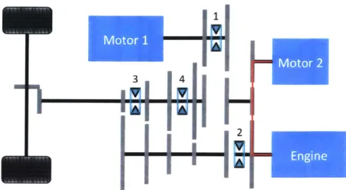
Figure 2-2: Two-motor clutchless hybrid architecture. Gears are grey, shafts are black, and synchronizers are light blue. Motor 1 is used for electric drive and torque
fill, and motor 2 is used for cranking and speed matching. All driving modes available
on a traditional dual clutch vehicle are possible.
starter motor, 1st gear ratio, and 12 V battery are removed. First gear is replaced by launch from the electric motor, which is sized to avoid negative consequences on 0-60 mph time. To achieve the same 0-60 mph acceleration, the torque from the electric motor must meet or exceed the torque available from the engine in 1st gear. The torque limit for acceleration is the friction limit of the tires, beyond which the wheels will slip. The rest of the ratios in the transmission can be adjusted accordingly to account for the replacement of first gear. A dog clutch (label 2 in Fig. 2-2) is used to couple the engine to the transmission. Motor 1 is primarily used for all-electric driving and torque fill between shifts, and motor 2 is used for ICE cranking, speed matching during a gearshift, and generating power for drive and charge mode. Details for these driving modes are discussed in more detail below.
Functionality and driving modes that are achievable with this setup include the following (with full descriptions and figures below):
" ICE cranking " EM only driving
* EM reversing
* Regenerative braking
" Park and charge mode
* Drive and charge mode
" Torque fill during gearshift
* Speed matching during gearshift
" Vehicle launch method 1 (EM only, friction limit) " Engine roar during launch
" Turbo pre-spooling with motor 2 acting as load
" Vehicle launch method 2 (EMI, EM2, and ICE - bump start engine) • Full power driving with ICE and both EMs.
ICE cranking will occur with synchro 2 centered (engine disconnected). Motor 2
is used to crank the ICE (Fig. 2-3). This can occur at any time, whether or not the vehicle is moving under power from motor 1. Motor 1 can be used as an additional power source for cranking in cold weather by shifting synchro 1 right (Fig. 2-4).
EM only driving and EM reversing both occur through motor 1 (Fig. 2-5). The
engine is disconnected for these two modes (synchro 2 centered). A series of different electric gear ratios can be achieved. Synchro 1 positioned left gives a single ratio. Synchro 1 positioned right gives four additional possible ratios. Motor 2 can also be used for electric driving through four ratios. Since the reverse gear is removed in this architecture, the EM is always used to drive in reverse. Additionally, since no friction clutch is present, low speed forward driving is also achieved with the electric motor, as the vehicle must be moving sufficiently fast to couple the ICE to the transmission without a clutch.
3 4
2
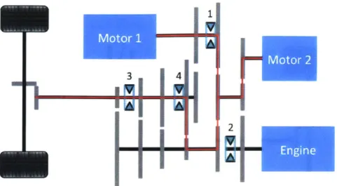
Figure 2-3: ICE cranking with motor 2 and park and charge are both implemented with the power path shown in this image in red.
REFE
W. W2
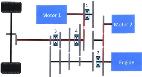
Figure 2-4: ICE cranking with motor 1. Both motors can be used together to crank for cold weather starting. Power path is shown in red.
i-fl--4'I
Figure 2-5: EM driving, EM reversing, and regenerative braking can happen with one of both electric motors, and motor 1 can be used in either gear ratio by moving synchro 1 left or right.
Regenerative braking can occur through motor 1 at any time, and additionally can
occur through motor 2 when it is connected to the drivetrain. This energy is stored in the batteries, and extends the all-electric range.
Park and charge mode occurs by using the engine to rotate motor 2, which acts
as a generator to recharge the batteries. Recharging can occur at a variety of charge rates based on the needs of the vehicle. For faster recharging, the load torque of the EM is increased, and ICE torque is increased to maintain the desired RPM for recharging.
Drive and charge mode is the same as park and charge, but motor 1 will propel
the vehicle (Fig. 2-6). This is how a series hybrid functions. If the vehicle has to drive long distance at low speed, drive and charge mode can be initiated when the battery state of charge is low, and stop once the battery is full. The peak efficiency recharge rate (considering ICE and EM efficiency) can be used to maximize fuel economy when driving in this mode.
Torque fill is when an electric motor is used to deliver power even when a gearshift
is occurring. With a dual clutch transmission, there is a nearly seamless shift between gear ratios. This occurs since as one clutch is disengaging one ratio, the second clutch
2:
Figure 2-6: Drive and charge mode and vehicle launch method 1. Power path is shown in red. For drive and charge motor 1 is used to propel the vehicle, and the engine is run at a high efficiency point to recharge the batteries through motor 2. This layout is also used to achieve engine roar during launch, and turbo pre-spool.
is engaging the second ratio [18]. Since the clutch is removed in this architecture, a brief period of torque interruption will occur during a shift event. To avoid unac-ceptable torque interruption and achieve similar vehicle performance, it is necessary to use motor 1 to apply torque during a gearshift event. A driver perceives torque dropout more significantly at lower vehicle speeds, when the power output of the elec-tric motor can adequately fill in the necessary torque. Additionally, for brief periods of time, the EM can be overdriven at a higher than rated torque to help match the necessary torque and prevent driver dissatisfaction.
Speed Matching is when the electric motor is used to assist in bringing the internal
combustion engine (ICE) to the proper speed for a new gear ratio. Since there is no clutch present, a speed difference between the engine and transmission cannot be tolerated, thus the speeds must be matched. While several methods can be used to quickly change the engine speed, controlling this accurately is a challenge. A typical ICE can accelerate without a load very quickly. By changing the timing of the spark or not injecting certain cylinders, deceleration of the engine can occur more quickly, since the engine will not produce power if injection is skipped. Additionally,
compressing air with the pistons of without adding fuel (the same technique used for engine braking) will help to slow the engine quickly. These methods, in partnership with an electric motor, can be used to quickly change speed for a new ratio.
Torque zeroing is necessary for shifting out of gear. Since there is no clutch, for the
engine to disconnect from the transmission, there must be minimal torque across the dogtooth coupling to allow for disengagement without significant positive or negative torque pulses and resulting drivetrain oscillations. To achieve torque zeroing before a shift, the throttle is decreased. When the torque is low or zero, synchro 2 can be shifted to disengage.
Vehicle launch method 1 involves using motor 1 to launch the vehicle at the friction
limit of the tires. The engine cannot be running and coupled to the drivetrain when the vehicle is not moving. Since no friction clutch is present, they must be coupled when the speeds match. If the engine is running, when the vehicle obtains the proper speed, the synchro 2 can shift to engage the engine. If the engine is not running, motor 2 can crank the engine before engagement.
Engine roar during launch is achieved by running the engine through a desired
RPM pattern when the vehicle is launching with motor 1. Thus, instead of a nearly silent electric launch, the launch will still sound similar to a traditional ICE launch, an aspect that is important to many performance vehicle owners.
Turbo pre-spooling can be accomplished during launch as well. When the engine
is disconnected from a load, even if it is turning, it cannot provide enough enthalpy in the exhaust stream to spool a turbocharger and build pressure in the engine air intake. By using motor 2 as a load on the engine, the turbocharger can spool, and upon engine connection to the drivetrain, turbo lag (a delay in increased power from the engine, caused when the turbo takes time to spool and begin supplying pressurized air, resulting in increased engine power) can be minimized. By using this method, the engine can be operating at its higher power level (with more intake air from the turbo), with a turbocharger that is sufficiently spooled from the additional load from the electric motor. As such, turbo lag is no longer experienced during vehicle
acceleration.
A full shift even will occur as follows (Fig. 2-7). First, the engine and motor 1
must torque zero, such that the desired synchronizer can be shifted. Once there is no torque through the coupling, the synchronizer can move to the neutral position. During this time, motor 1 can be torque filling to minimize the feel of torque loss on the vehicle performance. Upon synchronizer motion to neutral, speed matching can commence. The electric motor and engine will accelerate (for an upshift) or decelerate (for a downshift). The EM is beneficial here, as it is more controllable than the engine alone. A desired speed can be set, and the EM will reach and hold that speed quickly and accurately. Thus, the electric motor can be used to help manage and smooth engine speed. Upon matched speeds, the new ratio can be selected.
Vehicle launch method 2 is basically a "bump start" of the engine. In this method,
the engine is off, and synchro 2 is shifted left (Fig. 2-8). Either or both electric motors can launch the vehicle, and the engine will turn over and start. Once at the proper RPM, fuel is introduced and the engine can begin to provide power for the launch event.
Full power driving is performed when all three power sources are delivering power
to accelerate the vehicle. Once the vehicle is launched, all three elements can provide propulsive power. For launch method 1, motor 1 is used to launch the vehicle, and once to speed, the ICE and motor 2 can couple and add power. For launch method 2, once the ICE is cranked and started from forward vehicle motion, it can deliver power for propulsion.
2.2.1
Two-Motor Clutchless Architecture Prototype
A prototype was developed to demonstrate the feasibility of shifting without a clutch
(Fig. 2-9). Key features tested with this setup include torque zeroing and speed matching. The setup consists of two parallel shafts with a synchronizer set on one shaft, and two gears on the second shaft that mesh with the gears on the synchro-nizer. The gears were taken from a commercially manufactured transmission. A large
(a) First Gear Ratio
3 4
1
2
(b) Neutral
(c) Second Gear Ratio
Figure 2-7: Shown here is ashift event during standard driving with the power path shown in red. The vehicle starts out in the first ratio. Once engine torque is reduced, synchro 4can move to neutral. Motor 2is used to help rapidly change the speed of the ICE for the new ratio
(speed
matching) and simultaneously motor 1is used to torque fill. Once speed matching is complete, synchro 4can engage the new ratio.2
Figure 2-8: Combined power path (shown in red) and vehicle launch method 2. With this configuration, all three power sources can be used to propel the vehicle. Additionally, the engine can be bump started in this mode (or with one of the electric motors disengaged) by accelerating the vehicle resulting in cranking of the ICE.
hobbyist servo motor was used to actuate the shift fork to move the synchronizer. Speed controllers allow for speed control of each motor, and Hall effect sensors and tachometers are used to measure and display shaft speed. The transmission bearings were press fit into custom machined Delrin bearing blocks, which were mounted to an aluminum base.
Two specific qualitative tests were performed with this setup - torque zeroing before disengagement and speed matching before engagement. To disengage a syn-chronizer, the torque across the synchro must be minimal. If high torque exists, upon disengagement a drivetrain shock would be felt. Additionally, high torque across a synchro would require high actuation force, as the dogteeth are shaped with undercuts to prevent disengagement with torque. These undercuts create a force that opposes any force from an actuator trying to disengage the synchro from a selected gear. To properly engage a gear, the speeds must be matched. In a typical transmission, the conical friction elements in the synchronizer change the speed of the layshaft before the synchronizer is fully engaged. Since no clutch is present, the friction elements
Figure 2-9: The bench setup developed to test clutchless shifting is shown here. The motor on the left represents the ICE, and the motor on the right represents the vehicle moving at an approximately constant velocity. Tests to understand gear disengage-ment through torque zeroing, speed matching, and engagedisengage-ment were performed with this setup.
cannot sufficiently synchronize the speed difference of the ICE, given its larger iner-tia. It is necessary to actively change the ICE speed before a new gear engagement, which is done through control of the ICE and EM together to achieve fast gearshifts. Disengagement and engagement tests were performed. When disengaging, if high torque through the coupling was present, large shift force is necessary, and shocks can be witnessed in the system. Zeroing the torque through the synchronizer reduces shift force and shocks. Additionally, speed matching was validated. When shifting without a friction element in the synchro, if a speed difference exists, grinding of the dogteeth occurs. By speed matching using the EM, a shift can be completed even without friction elements present. While this was an early stage setup with minimal sensors or data acquisition capabilities, both concepts tested behaved as expected, and proved worthwhile for further development [19].
2.3
Single Motor Architecture
While the two-motor concept shows incredible promise, it is desirable to have a single electric motor architecture, as adding two EMs and accessories adds significant weight to the vehicle, much more than what is removed. The concept in Fig. 2-10 was
Figure 2-10: One motor, dual shaft, clutchless hybrid architecture. Power (shown in red) from ICE or EM can go to either shaft. The car can simultaneously be driving in 1st gear under power from the EM, and a different gear under ICE power. Depending on selected gear ratios, both can power the same input shaft, or different input shafts. designed with a single electric motor [20].
This architecture has several benefits over the two-motor architecture. It is able to achieve eight speeds from twelve individual gears. Additionally, it can drive in a large variety of configurations. In case one, the ICE can power one shaft, while the EM powers the other shaft. The top and bottom shafts can have different gears selected, allowing for 32 possible combinations of gear ratios. In case two, both power sources can power either the top or bottom shaft together, allowing for eight additional configurations.
All of the driving modes from the two-motor architecture are available with the
exception of:
" Drive and charge mode can only be performed when the vehicle is either moving
or stopped, but not easily while repeatedly starting and stopping.
" Torque fill and speed match cannot simultaneously occur, only one or the other
*Turbo pre-spool cannot be achieved, as there is no dedicated EM to put a load
on the engine and cause the turbo to spool.
2.3.1
City Driving Range Analysis
During city driving in stop-and-go conditions, the single electric motor must be used as the propulsion source, since the ICE cannot be running and connect to a transmission that is not spinning. Typically a friction clutch would disconnect the engine when the vehicle stops and allow for initial acceleration of the vehicle, but the clutch has been removed in this architecture. The electric motor is used instead, but over a long period of driving in traffic, it is important that the battery never becomes depleted.
An analysis was performed to show that during city driving, if the batteries are recharged when the vehicle is stopped in traffic, or when the vehicle is decelerating and regenerative braking, the state of charge of batteries will never fully deplete. This analysis was performed for the Artemis Urban driving cycle [21].
Figure 2-11 shows the driving cycle. Figure 2-12 shows this analysis of battery state of charge during the drive cycle. To calculate battery usage, the drive cycle was input to MATLAB. Next, torque at the motor (Tmotor) to achieve the drive cycle was calculated based on rolling resistance, aerodynamic drag, and driveline efficiency using
1
Tmotor = RwheelGgear(Ma + -pCdAv 2 +Froll), (2.1)
2
where Rwheel is the wheel radius, Ggear is the gear ratio from the wheel to the motor,
M is vehicle mass, a is vehicle acceleration, p is the air density, Cd is the vehicle drag coefficient, A is vehicle frontal area, v is vehicle velocity, and Fro is rolling resistance. Finally, power consumption is calculated based on instantaneous torque and speed at the electric motor, taking into account the gear ratio. At each timestep of the simulation, state of charge is equal to the previous charge state minus the energy used to move the vehicle in the previous timestep. In this simulation, a 4.5 kWh
15
5F[AN
I1*
11
100
~ ,AIyj
0 200 400 600 800 1000 1200 1400 1600 1800 2000
Time (s)
Figure 2-11: Artemis Urban Drive Cycle [21]. This drive cycle was used for the battery state of charge modeling. Any time the vehicle is stopped, the battery can be recharged by the ICE. When the vehicle is decelerating, regenerative braking is used to recharge the ICE.
50
401-• Battery capacity 4.5 kWh
• Initial charge state 4 kWh
30 • Start charging at 2.5 kWh
• Stop charging when full AlwaysCharging
-10~~ ~ ~~~Awy Chrarginge~na25khofaful 20
0 1. 10Charging with Charge Controller
0
-0Charge Controller (on at 2.5 kWh, off at full)
Charge Opportunities (Vehicle Stationary)
-201
0 200 400 600 800 1000 1200 1400 1600 1800 2000 Time (s)
Figure 2-12: Analysis of battery state of charge during Artemis Urban Driving Cycle. Battery is recharged when the vehicle is stationary if the charge mode is turned on. Even if the vehicle is not capable of drive and charge, by charging when the vehicle is stopped and regenerative braking, the battery will never become fully depleted.
battery is used, and the initial charge state is 4 kWh. The rate of charge is 40 kW, which is easily achievable with a 100+ kW electric motor which would be typical in a high-performance hybrid. Regenerative braking is assumed to be 72% efficient, as in 72% of the energy used to stop the vehicle is stored in the battery, which includes drivetrain and electrical system efficiency.
The following equations can be used to represent the flow of power from the battery during driving, with positive flow indicating the battery discharging.
TmotorWmotor 1 for Tmotor > 0
Pbatt= system (2.2)
Tmotorwmotornsystem for Tmotor < 0.
Pbatt is the power flowing from the battery, Tmotor is the motor torque, Wmotor is
the motor speed, and nsystem is the summation of drivetrain and electrical efficiency. When torque is positive, power leaves the battery, and negative torque represents regenerative braking, charging the battery. Therefore, power leaving the battery during positive torque events has an efficiency term of 1/n, as for a given torque, more power leaves the battery than in an ideal, perfect efficiency case.
The charging commences every time the vehicle stops, and ends once the vehicle begins forward motion. A full start stop event would initiate with the electric motor propelling the vehicle and the vehicle coming to a stop. Then the EM would dis-engage from the forward drive part of the transmission and dis-engage with the engine for charging (the engine could either be off and the EM would crank the engine, or if already at idle, would speed match and engage). Once the driver lifts his foot off the brake, the EM would decouple from charging, and engage to propel the vehicle forward. The engine can either be left at idle, or shutdown, as it can be restarted by the EM when charging reinitiates.
In Fig. 2-12, shown in green is the state of charge if the battery charges every time the vehicle stops. Shown in blue is the battery charge if ICE charging is never per-formed. Shown in pink is every time the vehicle has the opportunity to charge (any time it is stopped) with high as true/can charge and low as false/cannot charge.